SERVICE MANUAL
DA
TA
BASIC VIDEO MECHANISM
:D33K-4HF/PAL-HREW(6721R-0251A)<8200>
:D33K-4HF/PAL(6721R-0250A)<7700/5700>
:D33K-4HD/NP-VCR(6721R-0230F)<990>
:D33K-2HD/PAL-VCR(6721R-0212A)<915>
STEREO VIDEO CASSETTE RECORDER
<8200/7700/5700>
VIDEO CASSETTE RECORDER<990/915>
HV-FX8200
HV-FX7700
HV-FX5700
HV-FX990
HV-GX915
S/M Code No. 09-007-347-2R6
EH
EH
EH
Z
Z
REVISION
This Service Manual is the "Revision Publishing" and replaces "Simple Manual"
(S/M Code No. 09-007-347-2T6).
HV-FX7700, FX5700
HV-FX8200
HV-FX990, GX915

2
TABLE OF CONTENTS
SPECIFICATIONS ............................................................ 3
ACCESSORIES LIST ....................................................... 3
DISASSEMBLY INSTRUCTIONS ..................................... 4
SERVICE POSITION ........................................................ 5
VCR TEST TAPE INTERCHANGEABILITY TABLE ........ 6
ELECTRICAL MAIN PARTS LIST .............................. 7 ~ 9
TRANSISTOR ILLUSTRATION ........................................ 9
WIRE HARNESS DIAGRAM .......................................... 10
BLOCK DIAGRAM ................................................. 11 ~ 22
SCHEMATIC DIAGRAM
1. POWER/TUNER/NICAM <8200/7700/5700> .... 23 ~ 24
2. POWER/TUNER <990/915> .............................. 25 ~ 26
3. AUDIO/VIDEO SECTION ................................... 29 ~ 30
4. Hi-Fi AUDIO/SCART <8200/7700/5700> ........... 31 ~ 32
5. SCART <990/915> ............................................. 33 ~ 34
6. SYSTEM CONTROL/SERVO
<8200/7700/5700> ............................................. 35 ~ 36
7. SYSTEM CONTROL/SERVO <990/915> .......... 39 ~ 40
8. KEY1 <8200/7700/5700> ........................................... 47
9. KEY1 <990/915> ........................................................ 47
10. KEY2 <8200/7700/5700> ......................................... 48
11. KEY2 <990/915> ...................................................... 48
WAVEFORM
AUDIO/VIDEO SECTION ............................................... 28
SYSTEM CONTROL/SERVO SECTION ....................... 38
VOLTAGE CHART
1. POWER SECTION ..................................................... 25
2. AUDIO/VIDEO SECTION ........................................... 27
3. Hi-Fi AUDIO/SCART SECTION ................................. 33
4. SYSTEM CONTROL/SERVO SECTION ................... 37
FL DISPLAY ............................................................ 41 ~ 42
WIRING
1. MAIN C.B <8200/7700/5700> ............................ 43 ~ 44
2. MAIN C.B <990/915> ......................................... 45 ~ 46
3. KEY1 C.B <8200> ...................................................... 49
4. KEY2 C.B <8200> ...................................................... 49
5. KEY1 C.B <7700/5700> ............................................. 49
6. KEY2 C.B <7700/5700> ............................................. 49
7. KEY1 C.B <990/915> ................................................. 50
8. KEY2 C.B <990/915> ................................................. 50
9. NICAM C.B ................................................................. 51
ADJUSTMENT ........................................................ 52 ~ 53
IC DESCRIPTION ................................................... 54 ~ 57
MECHANICAL EXPLODED VIEW 1/1 ........................... 58
MECHANICAL MAIN PARTS LIST 1/1 ......................... 59
MECHANISM EXPLODED VIEW 1/3~3/3 .............. 60 ~ 64
MECHANISM MAIN PARTS LIST 1/3~3/3 ............. 61 ~ 65
DECK MECHANISM PARTS LOCATIONS
Top View .......................................................................... 66
Bottom View .................................................................... 66
DECK MECHANISM DISASSEMBLY
1. Drum Assembly ......................................................... 67
2. Plate Assembly Top ................................................... 69
3. Holder Assembly CST ............................................... 69
4. Guide CST ................................................................ 69
5. Bracket Side (L)/Bracket Assembly Door .................. 69
6. Arm Assembly F/L ..................................................... 69
7. Lever Assembly S/W ................................................. 69
8. Arm Assembly Cleaner .............................................. 70
9. Head F/E ................................................................... 70
10. Base Assembly A/C Head ........................................ 70
11. Brake Assembly S .................................................... 71
12. Brake Assembly T .................................................... 71
13. Arm Assembly Tension ............................................. 71
14. Reel S & Reel T ....................................................... 71
15. Support CST ............................................................ 72
16. Base Assembly P4 ................................................... 72
17. Opener Lid ............................................................... 72
18. Arm Assembly T/up .................................................. 72
19. Arm Assembly Pinch ................................................ 72
20. Belt Capstan/Motor Capstan .................................... 73
21.Clutch Assembly D33-K ............................................ 73
22. Lever F/R ................................................................. 73
23. Gear Assembly H-Up/D-K or
Gear Assembly Up/D-K ............................................ 73
24. Bracket Assembly Jog .............................................. 74
25. Guide Rack F/L, Gear Rack F/L ............................... 74
26. Brake Assembly Capstan ......................................... 74
27. Gear Drive/Gear Cam/Gear Connector ................... 75
28. Bracket Assembly L/D motor .................................... 75
29. Gear Sector .............................................................. 76
30. Base Tension/Plate Slider/Lever Tension ................. 76
31. Gear Assembly P3/Gear Assembly P2 .................... 77
32. Base Assembly P3/Base Assembly P2 .................... 77
33. Arm Assembly Idler or Arm assembly Idler Jog ........ 77
DECK MECHANISM ADJUSTMENT
Tools and Fixtures for service ......................................... 78
1. Mechanism Alignment Position Check ....................... 79
2. Preparation for Adjustment ........................................ 80
3. Checking Torque ........................................................ 80
4. Guide Roller Height Adjustment ................................. 81
4-1. Preliminary Adjustment .......................................... 81
4-2. Precise Adjustment ................................................ 81
5. Audio/Control (A/C) Head Adjustment ........................ 82
5-1. Preliminary Adjustment .......................................... 82
5-2. Confirm that the Tape Path smoothly between
the Take-up Guide and Pinch Roller ..................... 83
5-3. Precise Adjustment (Azimuth Adjustment) ............. 83
6. X-Value Adjustment .................................................... 83
7. Adjustment after Replacing Drum Assembly
(Video Heads) ............................................................. 84
8. Check the Tape Travel after Reassembling
Deck Assembly ............................................................ 84
8-1. Checking Audio and RF Locking Time
during Playback and after CUE or REV ................ 84
8-2. Check for Tape Curling or Jamming ....................... 84
MAINTENANCE/INSPECTION PROCEDURE
1. Check before starting Repairs ................................... 85
2. Required Maintenance ............................................... 86
3. Scheduled Maintenance ............................................ 86
4. Supplies Required for Inspection and Maintenance .. 86
5. Maintenance Procedure ............................................. 86
5-1. Cleaning ................................................................. 86
5-2. Greasing ................................................................ 87
MECHANISM TROUBLESHOOTING GUIDE
1. Deck Mechanism ............................................... 88 ~ 90
2. Front Loading Mechanism ................................. 91 ~ 92

3
REF. NO
PART NO.
KANRI
DESCRIPTION
NO.
ACCESSORIES LIST
SPECIFICATIONS
· Design and specifications are subject to change without notice.
<HV-FX8200, FX7700, FX5700, FX990>
Video recording system
Rotary 2 head helical scanning system
Video head
Double azimuth 4 heads
Tuner system
Frequency synthesized tuner
TV system
B/G
Video signal system
PAL color signal, 625 lines, 50 fields
Usable cssettes
VHS video cassettes
Recording/playback time
PAL/MESECAM
SP: 5 hours max. with E-300 tape.
LP: 10 hours max. with E-300 tape
NTSC (Playback only)
SP: 3 hours 30 minutes max.
with T-210 tape
LP: 7 hours max. with T-210 tape
EP: 10 hours 30 minutes max.
with T-210 tape
Tape speed
PAL/MESECAM
SP: 23.39 mm/s
LP: 11.69 mm/s
NTSC (Playback only)
SP: 33.35 mm/s
LP: 16.67 mm/s
EP: 11.12 mm/s
Hight speed rewind time:
Approx. 1 min. with E-180 tape
<FX8200>
Rewind time:
Approx. 3 min. with E-180 tape
<FX7700, FX5700, FX990>
Channel coverage
VHF: C02 to C12
UHF: C21 to C71 <FX8200, FX7700>
UHF: C21 to C69 <FX5700, FX990>
CATV: S01 to S41
Video input
0.5 - 2.0 Vp-p, 75 ohm, unbalanced
Video output
1.0 Vp-p, 75 ohm, unbalanced
Horizontal resolution
240 lines (SP)
Video S/N
43 dB (SP)
Audio track
3 tracks (Hi-Fi sound 2 tracks, Normal
sound 1 track)
<FX8200, FX7700, FX5700>
1 track (Normal sound) <FX990>
Audio input
SCART: -6 dBm, more than 10 k ohm
Audio output
SCART: -6 dBm, less than 1 k ohm
Hi-Fi frequency response 20 Hz - 20 kHz
<FX8200, FX7700, FX5700>
Hi-Fi dynamic range
More than 87 dB (SP)
<FX8200, FX7700, FX5700>
Hi-Fi Wow & Flutter
Less than 0.01%(SP)
<FX8200, FX7700, FX5700>
Operating temperature:
5
°C to 35 °C
Power requirements
200 - 240 V AC, 50 Hz
Power consumption
19 watts <FX8200, FX7700, FX5700>
16 watts <FX990>
TYPE 2.1 watts (power save mode.)
Dimensions
360 (W) x 270 (D) x 94.5 (H) mm
(141/
4 x 10
3/
4 x 3
3/
4 in.)
Weight
Approx. 3.5 kg (7.7 lbs.)
<HV-GX915>
Video recording system
Rotary 2 head helical scanning system
Video head
Double azimuth 2 heads
Tuner system
Frequency synthesized tuner
TV system
B/G
Video signal system
PAL color signal, 625 lines, 50 fields
Usable cssettes
VHS video cassettes
Recording/playback time
PAL/MESECAM
5 hours max. with E-300 tape.
NTSC (Playback only)
3 hours 30 minutes max.
with T-210 tape
Tape speed
PAL/MESECAM
23.39 mm/s
NTSC (Playback only)
33.35 mm/s
Rewind time:
Approx. 3 min. with E-180 tspe
Channel coverage
VHF: C02 to C12
UHF: C21 to C69
CATV: S01 to S41
Video input
0.5 - 2.0 Vp-p, 75 ohm, unbalanced
Video output
1.0 Vp-p, 75 ohm, unbalanced
Horizontal resolution
240 lines
Video S/N
43 dB
Audio track
1 track (Normal sound)
Audio input
SCART: -6 dBm, more than 10 k ohm
Audio output
SCART: -6 dBm, less than 1 k ohm
Operating temperature:
5
°C to 35 °C
Power requirements
200 - 240 V AC, 50 Hz
Power consumption
16 watts
TYPE 2.1 watts (power save mode.)
Dimensions
360 (W) x 270 (D) x 94.5 (H) mm
(141/
4 x 10
3/
4 x 3
3/
4 in.)
Weight
Approx. 3.5 kg (7.7 lbs.)
1
S8-35R-P00-54Z
INSTRUCTION ASSY ABFA929NP 3NA<82>
1
S8-35R-P00-54M
INSTRUCTION ASSY CBFA918NP NSA<77>
1
S8-35R-P00-55N
INSTRUCTION ASSY CBFA911NP NSA<57>
1
S8-35R-P00-54K
INSTRUCTION ASSY CBFA408P NSA4<99>
1
S8-35R-P00-54W
INSTRUCTION ASSY ABFA201P 3NA1<91>
2
S7-11R-1P0-24L
REMOTE CONTROLLER ASSY(BFA929N<82>
2
S7-11R-1P0-24C
REMOTE CONTROLLER ASSY<77,99>
2
S7-11R-1P0-24N
REMOTE CONTROLLER ASSY(BFA911P<57>
2
S7-11R-1P0-24P
REMOTE CONTROLLER ASSY(BFA201P<91>
3
S8-610-33B-000
CABLE SET ASSY<82,77,57>
TYPE
MODEL NAME SUFFIX
<82>
HV-FX8200
EH
<77>
HV-FX7700
EH
<57>
HV-FX5700
EH
<99>
HV-FX990
Z
<91>
HV-GX915
Z
3
S8-615-05B-000
CABLE SET ASSY<99,91>
4
S8-615-05R-000
CABLE ASSY<82,77,57>
5
S5-640-18B-000
PLUG ASSY PHONO CORD<82,77,57>
4
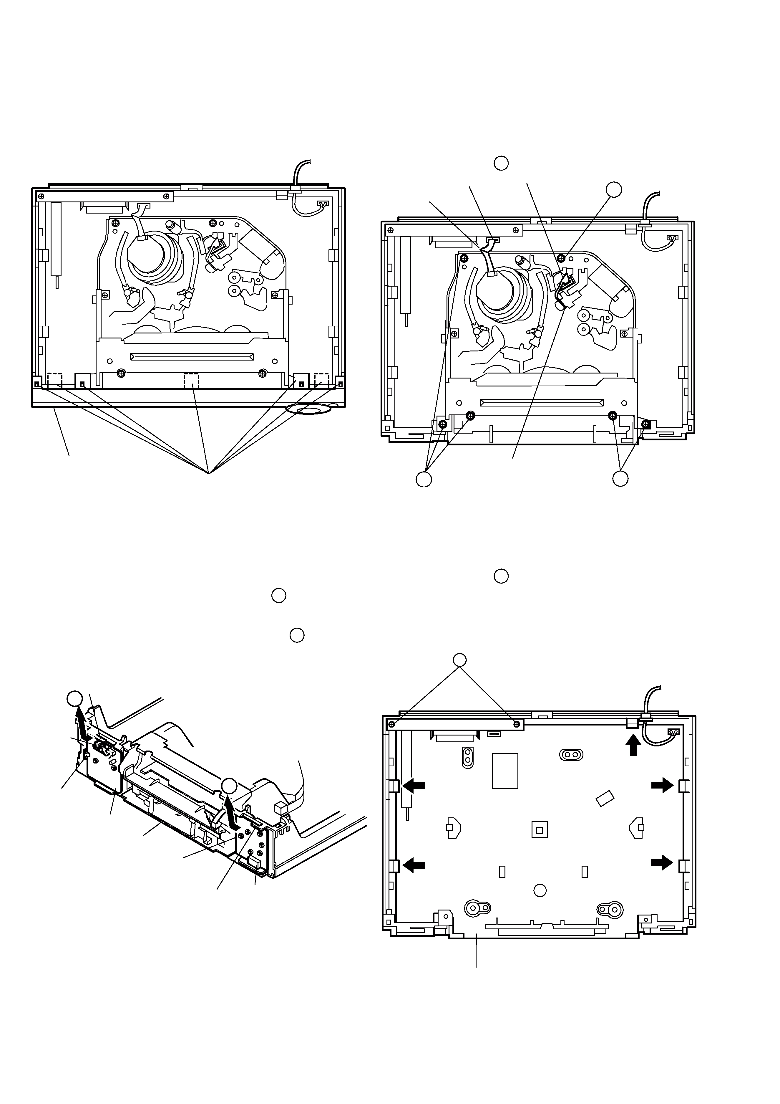
DISASSEMBLY INSTRUCTIONS
1. Top Case Removal
1) Remove 4 screws holding the top case.
2. Panel Front Removal (see Fig. 1)
1) Release 7 tabs, and then remove the panel front.
Fig. 1
3. Key1 C.B. and Key2 C.B. Removal (see Fig. 2)
1) Release 2 tabs, and then remove Key2 C.B. from the con-
nector (PKM02) in the direction of arrow 1 .
2) Release the tab, and then remove Key1 C.B. from the
connector (PKM01) in the direction of arrow 2 .
Fig. 2
4. Mechanism Removal (see Fig. 3)
1) Disconnect the drum FF cable from the connector
(PMD01) on the Main C.B.
2) Disconnect the ACE head FF cable from the connector
(P3D02) on the Main C.B.
3) Remove 6 screws A .
Fig. 3
5. Main C.B. Removal (see Fig. 4)
1) Remove 2 screws B holding the panel assy, distri-butor.
2) Release 5 tabs, and then simultaneously lift the panel as-
sembly, distributor and Main C.B. to remove them.
Fig. 4
PANEL
FRONT
TAB
TAB
TAB
TAB
KEY1 C.B
KEY2 C.B
MAIN C.B
PKM02
PKM01
1
2
FF CABLE
P3D02
FF CABLE
PMD01
A
A
A
PANEL ASSY,
DISTRIBUTOR
MAIN C.B
TAB
TAB
TAB
TAB
TAB
B
5
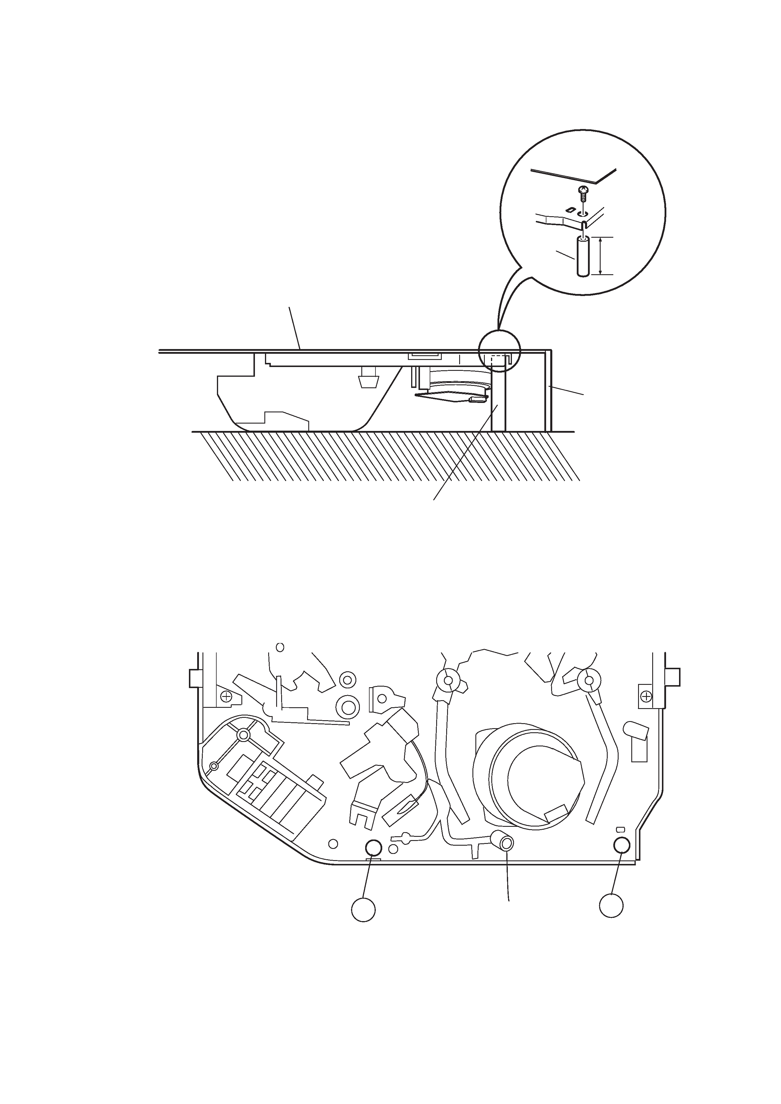
SERVICE POSITION
To set the mechanism to the service position in active status:
Insert a spacer as shown below: The service position can be set in the stable status without any defective contact.
Location
Install spacers at locations (A) and (B).
MAIN C.B
D33 MECHANISM
SPARSER
60mm
MAIN C.B
D33
MECHA
SPARSER
REAR PANEL
A
B
Top View
CYLINDER
HEAD CLEANER