AV SURROUND RECEIVER
RECEPTOR CON SISTEMA DE SONIDO PERIMÉTRICO PARA AUDIO-VÍDEO
RECEPTEUR AV SURROUND
U
OPERATING INSTRUCTIONS
MANUAL DE INSTRUCCIONES
MODE D'EMPLOI
En (English)
8C-AR6-903-21
020615CCK-H-S
F (Français)
AV-NW30
AV-NW31(forHT-NW300,HT-DV2300)
For assistance and information
call toll free 1-800-BUY-AIWA
(United States and Puerto Rico)
E (Español)
Owner's record
For your convenience, record the model number and serial number (you will find them on
the rear of your unit) in the space provided below
. Please refer to them when you contact
your Aiwa dealer in case of dif ficulty .
Model No.
Serial No. (Lot No.)
AV-NW30/AV-NW31
2 ENGLISH
ENGLISH
WARNING
TO REDUCE THE RISK OF FIRE OR
ELECTRIC SHOCK, DO NOT EXPOSE THIS
APPLIANCE TO RAIN OR MOISTURE.
Portable cart - An appliance and cart combination
should be moved with care. Quick stops, excessive
force, and uneven surfaces may cause the
appliance and cart combination to overturn.
Ventilation - The unit should be situated with adequate space
around it so that proper heat ventilation is assured.
Allow 10 cm
clearance from the rear and the top of the unit, and 5 cm from
the each side.
Slots and openings in the cabinet and the back or bottom are
provided for ventilation, and to ensure reliable operation of the
unit and to protect it from overheating, these openings must not
be blocked or covered.
The openings should never be blocked
by placing the unit on a bed, sofa, rug or other similar surface.
This unit should not be placed in a built-in installation such as a
bookcase unless proper ventilation is provided.
Object and Liquid Entry - Never push objects of any kind into
this unit through the cabinet slots as they may touch dangerous
voltage points or short-circuit parts that could result in a fire or
electric shock. Never spill liquid of any kind on the unit.
Electric Power
Power Sources - This unit should be operated only from the
type of power source indicated on the marking label. If you are
not sure of the type of power supply to your home, consult your
appliance dealer or local power company
. To operate unit on
battery power , or other sources, refer to the operating instructions.
Grounding or Polarization - This unit is provided with a polarized
alternating-current line plug (a plug having one blade wider than
the other). This plug will fit into the power outlet only one way
.
This is a safety feature. If you are unable to insert the plug fully
into the outlet, try reversing the plug. If the plug should still fail to
fit, contact your electrician to replace your obsolete outlet. Do
not defeat the safety purpose of the polarized plug.
Power-Cord Protection - Power-supply cords should be routed
so that they are not likely to be walked on or pinched by items
placed upon or against them, paying particular attention to cords
at plugs, convenience receptacles, and the point where they exit
from the product.
Overloading - Do not overload wall outlets, extension cords,
integral convenience receptacles as this can result in a risk of
fire or electric shock.
Outdoor Antenna
Power lines - An outside antenna system should not be located
in the vicinity of overhead power lines or other electric light or
power circuits, or where it can fall into such power lines or circuits.
When installing an outside antenna system, extreme care should
be taken to keep from touching such power lines or circuits as
contact with them might be fatal.
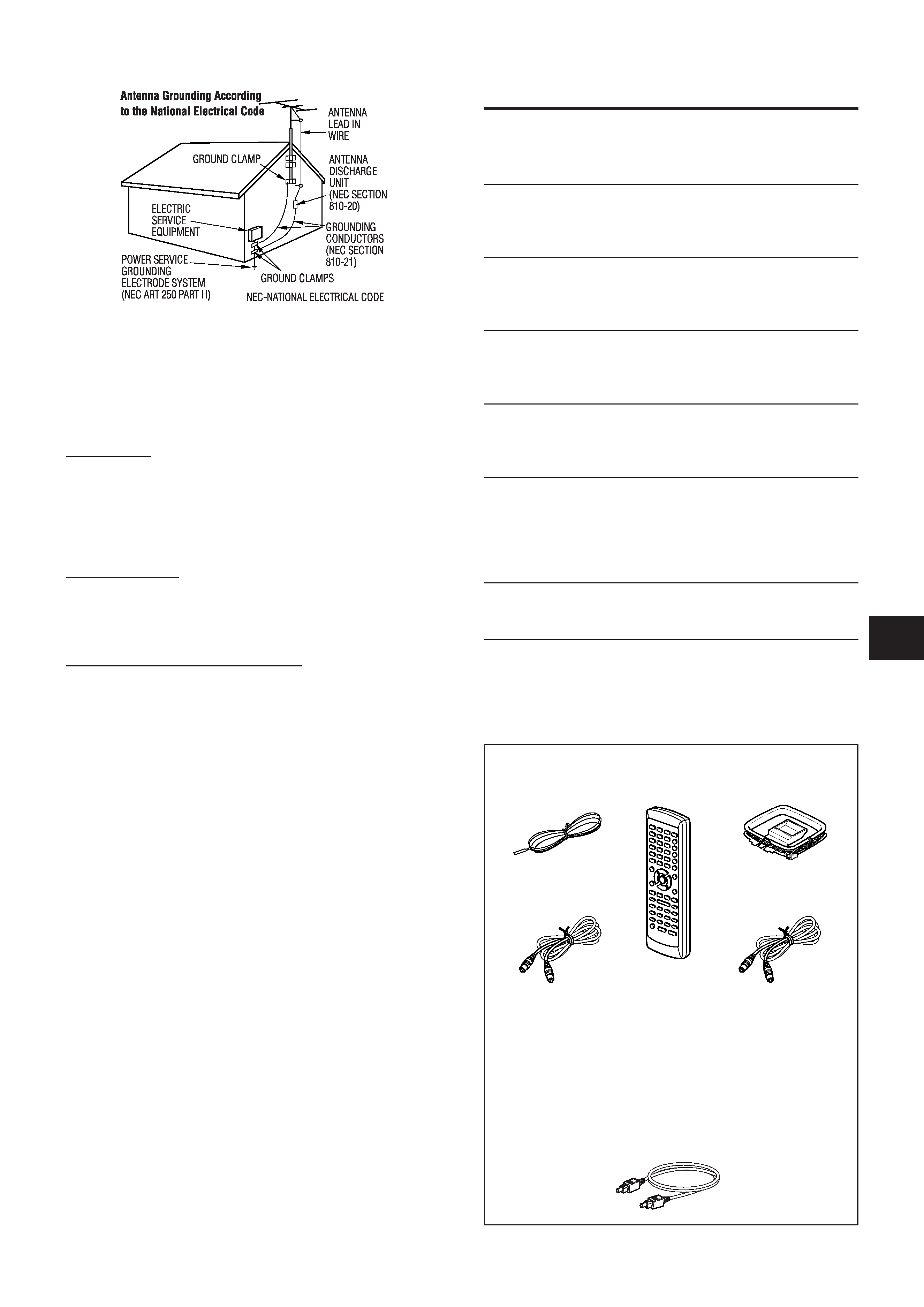
Outdoor Antenna Grounding - If an outside antenna or cable
system is connected to the unit, be sure the antenna or cable
system is grounded so as to provide some protection against
voltage surges and built-up static charges. Section 810 of the
National Electrical Code, ANSI/NFPA No.70, provides information
with regard to proper grounding of the mast and supporting
structure, grounding of the lead-in wire to an antenna discharge
unit, size of grounding conductors, location of antenna-discharge
unit, connection to grounding electrodes, and requirements for
the grounding electrode. See the figure.
RISK OF ELECTRIC SHOCK
DO NOT OPEN
"CAUTION: TO REDUCE THE RISK OF
ELECTRIC SHOCK,
DO NOT REMOVE COVER (OR BACK).
NO USER-SERVICEABLE PARTS INSIDE.
REFER SERVICING TO QUALIFIED
SERVICE PERSONNEL."
Explanation of Graphical Symbols:
The lightning flash with arrowhead symbol,
within an equilateral triangle, is intended to
alert the user to the presence of uninsulated
"dangerous voltage" within the product's
enclosure
that
may
be
of
sufficient
magnitude to constitute a risk of electric
shock to persons.
The exclamation point within an equilateral
triangle is intended to alert the user to the
presence
of
important
operating
and
maintenance (servicing) instructions in the
literature accompanying the appliance.
IMPORTANT SAFETY
INSTRUCTIONS
Read the Operating Instructions carefully and completely before
operating the unit. Be sure to keep the Operating Instructions
for future reference.
All warnings and cautions in the Operating
Instructions and on the unit should be strictly followed, as well
as the safety suggestions below
.
Warning
To prevent electric shock or injury
, these safety instructions should
be followed in the installation, use and servicing the unit.
Installation
Attachments - Do not use attachments not recommended by
the unit manufacturer as they may result in the risk of fire, electric
shock or injury to persons.
Water and Moisture - Do not use this unit near water - for
example, near a bathtub, washbowl, kitchen sink, or laundry tub,
in a wet basement, or near a swimming pool, and the like.
Heat - Do not use this unit near sources of heat, including heating
vents, stoves, or other appliances that generate heat. It also
should not be placed in temperatures less than 5°C (41°F) or
greater than 35°C (95°F ).
Mounting surface - Place the unit on a flat, even surface.
Accessories - Do not place this unit on an unstable cart, stand,
tripod, bracket, or table.
The unit may fall, causing serious injury
to a child or an adult, and serious damage to the appliance. Use
only with a cart, stand, tripod, bracket, or table recommended by
the manufacturer , or sold with the unit.
Any mounting of the
appliance should follow the manufacturer
's instructions, and
should use a mounting accessory recommended by the
manufacturer .
En
ENGLISH
3
Note to CATV system installer:
This reminder is provided to call the CA
TV system installer 's
attention to Section 820-40 of the NEC which provides guidelines
for proper grounding and, in particular
, specifies that the cable
ground shall be connected to the grounding system of the
building, as close to the point of cable entry as practical.
Lightning
For added protection for this unit receiver during a lightning storm,
or when it is left unattended and unused for long periods of time,
unplug it from the wall outlet and disconnect the antenna or cable
system. This will prevent damage to the unit due to lightning and
powerline surges.
Maintenance
Cleaning - Unplug this unit from the wall outlet before cleaning.
Do not use liquid cleaners or aerosol cleaners. Use a damp cloth
for cleaning.
Damage Requiring Service
Unplug this unit from the wall outlet and refer servicing to qualified
service personnel under the following conditions:
1) When the power cord or plug is damaged.
2) If liquid has been spilled, or objects have fallen into the unit.
3) If the unit has been exposed to rain or water
.
4) If the unit does not operate normally by following the operating
instructions. Adjust only those controls that are covered by
the operating instructions as improper adjustment of other
controls may result in damage and will often require extensive
work by a qualified technician to restore the unit to normal
operation.
5) If the unit has been dropped or the cabinet has been damaged.
6) When the unit exhibits a distinct change in performance - this
indicates a need for service.
Do not attempt to service this unit yourself as opening or removing
covers may expose you to dangerous voltage or other hazards.
Refer all servicing to qualified service personnel.
Replacement Parts - When replacement parts are required, be
sure the service technician has used replacement parts specified
by the manufacturer or having the same characteristics as the
original part. Unauthorized substitutions may result in fire, electric
shock or other hazards.
Safety Check - Upon the completion of any service or repairs to
this unit, ask the service technician to perform safety checks to
determine that the unit is in proper operating condition.
TABLE OF CONTENTS
IMPORTANT SAFETY INSTRUCTIONS ............................ 2
PREPARATIONS
CONNECTIONS .................................................................. 4
BEFORE OPERATION ........................................................ 8
SOUND
CUSTOM AUDIO ADJUSTMENT ....................................... 9
DSP SURROUND ................................................................ 9
BASIC OPERATIONS
SELECTION OF AUDIO/VIDEO SOURCE ....................... 10
RECORDING AN AUDIO SOURCE ................................. 11
RADIO RECEPTION
MANUAL TUNING ............................................................. 12
PRESET TUNING .............................................................. 12
DOLBY SURROUND AND DTS SURROUND
TURNING SURROUND ON AND OFF ............................. 13
SETTING SPEAKER SIZE AND DISTANCE ................... 14
ADJUSTING SPEAKER LEVEL BALANCE .................... 15
OTHER SETTINGS ........................................................... 16
TIMER
SETTING THE SLEEP TIMER .......................................... 17
GENERAL
CARE AND MAINTENANCE ............................................ 17
TROUBLESHOOTING GUIDE .......................................... 17
SPECIFICATIONS ............................................................. 18
PARTS INDEX ................................................................... 19
FM antenna
Remote control
AM antenna
Operating Instructions, etc.
Check your accessories
For the customers who bought the AV-NW31 (for HT-
NW300 and HT-DV2300)
· For the connections and operations of the speaker system
and the DVD player , refer also to the operating instructions
supplied with the speaker system (for HT
-NW300 and HT-
DV2300) or the DVD player (for HT -DV2300).
· The optical connecting cord is also supplied to the system
HT-DV2300).
Video connecting cord
(AV-NW31 only)
Coaxial connecting cord
(AV-NW31 only)
4 ENGLISH
CONNECTING EQUIPMENT
Jacks and plugs of the connecting cord are color-coded as follows:
Red jacks and plugs: For the rigtht channel of audio signals
White jacks and plugs: For the left channel of audio signals
Yellow jacks and plugs: For video signals
NOTE
Insert the plugs fully into the jacks. Loose connections may
produce a humming sound or other noise interference.
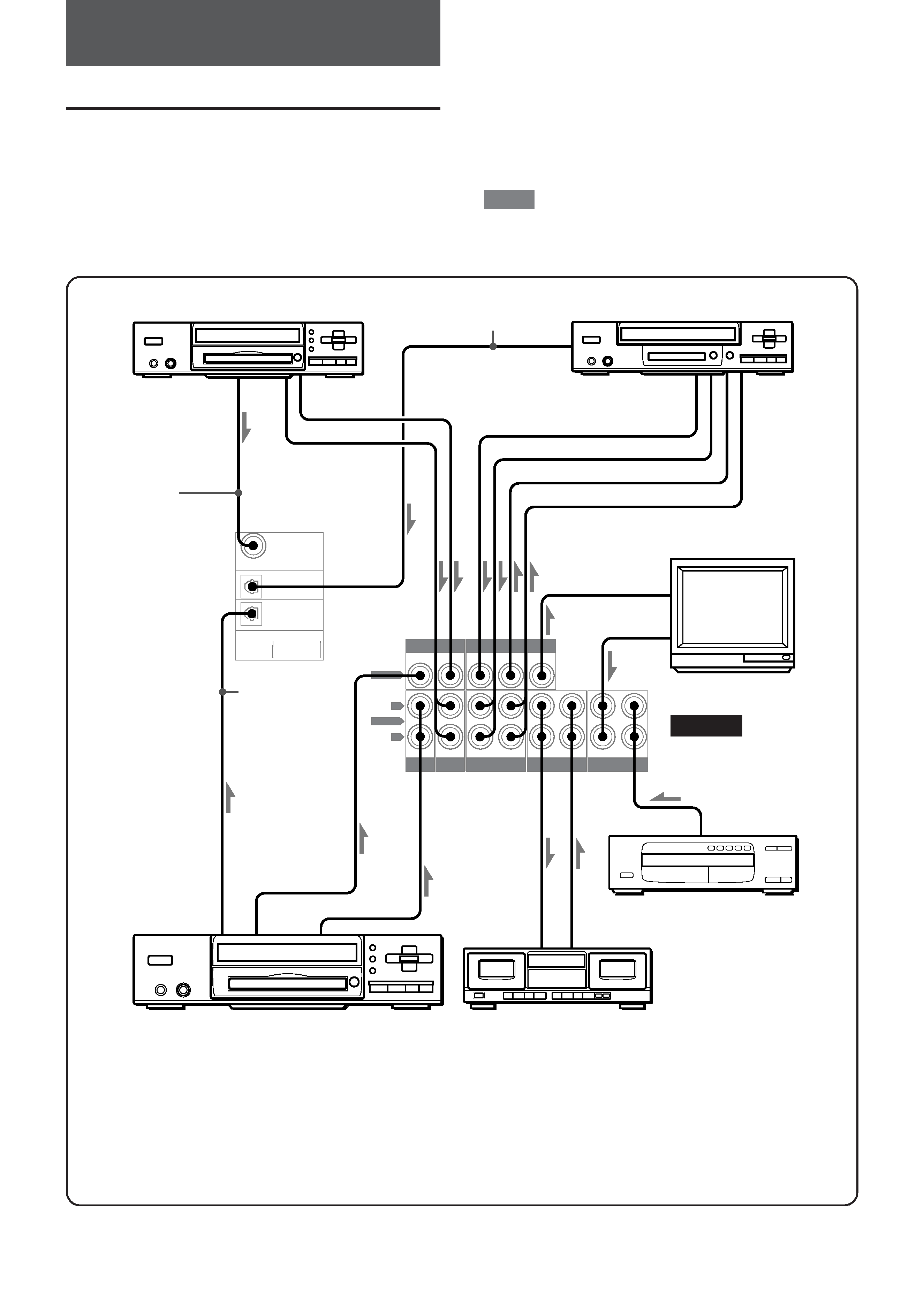
CONNECTIONS
Before connecting the AC cord
The rated voltage of your unit shown on the rear panel is 120 V
AC. Check that the rated voltage matches your local voltage.
IMPORTANT
Plug in the AC power cord to the
AC outlet after all other
connections are made.
*1 When connecting a monaural video, use a stereo-mono
connecting cord (not supplied).
*2 When connecting an LD player equipped with the
AC-3 RF OUT
terminal, use an RF demodulator unit.
Also connect the analog
AUDIO OUT terminals of the LD player to the receiver to play
all the sources. For further information, refer to the instructions
of the LD player .
PREPARATIONS
REAR
COAXIAL
(VIDEO 2)
OPTICAL
(VIDEO 1)
OPTICAL
(DVD)
DIGITAL IN
PCM
/ DOLBY DIGITAL
/ DTS
VIDEO
DVD
VIDEO 1 / MD
VIDEO 1 / MD
TAPE
AUX
CD
MONITOR
VIDEO 2
/ LD / TV
VIDEO 2
/ LD / TV
IN
IN
IN
IN
IN
IN
OUT
VIDEO OUT
OUT
IN
IN
IN
OUT
DVD
AUDIO
L
R
*3 Input sound through the DIGIT AL IN terminals (COAXIAL
(VIDEO 2), OPTICAL (VIDEO 1) and OPTICAL (DVD)) cannot
be recorded. When recording the sound from the DVD, CD, MD
or LD player , connect the analog AUDIO OUT terminals of the
player to the corresponding
AUDIO IN terminals of the receiver .
*4 With this connection, the picture noise may appear when playing
copy protected DVDs. In this case, it is recommended to connect
the VIDEO OUT terminal of the DVD player directly to a
TV set,
not through the receiver .
TV
DVD, video 2*1, LD*2 or cable TV
Optical connecting cord
Video 1*1 or MD player
to VIDEO OUT* 4
to AUDIO OUT
to COAXIAL
DIGITAL OUT
Coaxial
connecting cord
*3
*3
*3
Optical
connecting cord
to VIDEO OUT* 4
to AUDIO OUT
to LINE IN
to LINE OUT
Tape deck
DVD player
CD player
to LINE OUT
to AUDIO OUT
to VIDEO IN
to AUDIO IN
to VIDEO IN (V ideo 1)
to AUDIO OUT
to VIDEO OUT (Video 1)
uSignal stream
to OPTICAL
DIGITAL OUT
to OPTICAL DIGITAL OUT
En
ENGLISH
5
PREP
ARA
TIONS
SU
B
WO
OF
ER
OU
T
IMP:
8
CEN
TER
SPE
AKE
R
IMP:
8
SU
RR
OU
ND
SPE
AK
ER
S
R
L
IMP:
8
FRO
NT
SPE
AK
ER
S
RL
IMP:
8
FRO
NT
SPE
AK
ER
S
RL
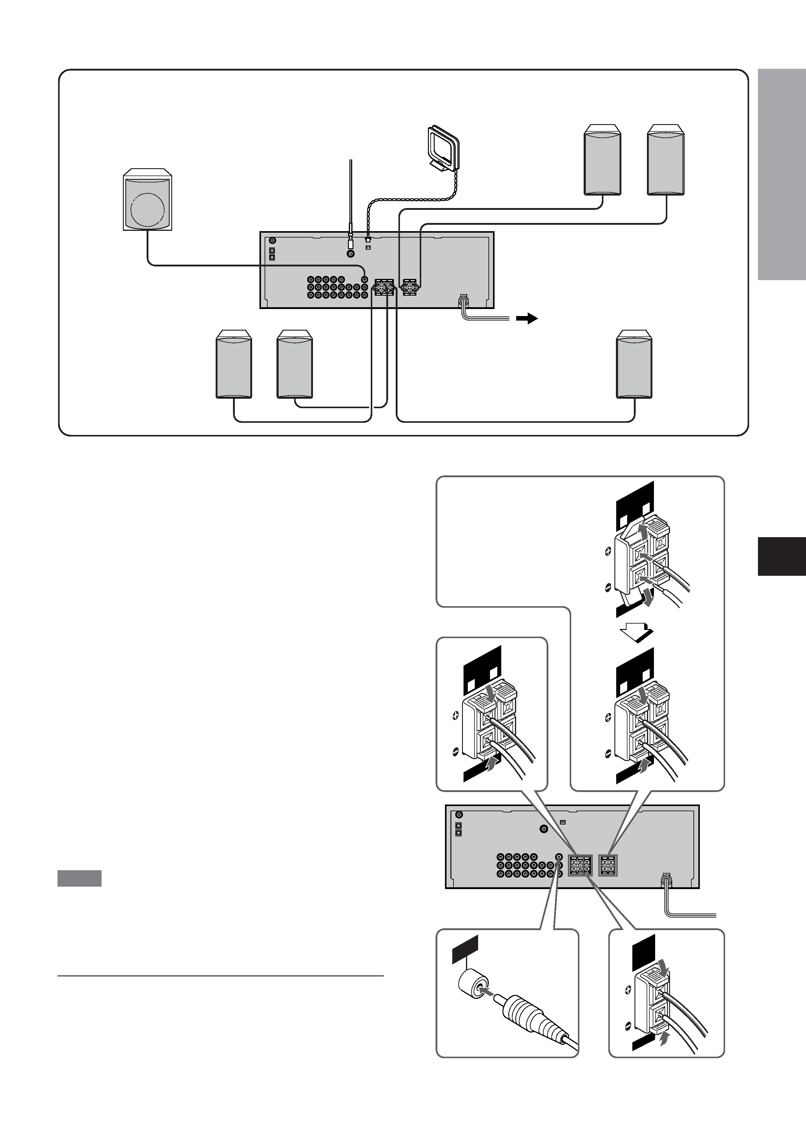
CONNECTING SPEAKERS 1
1
1
1
1
Speaker terminals
Connect front speakers, a center speaker
, surround speakers
and a sub woofer to the corresponding speaker terminals on the
unit:
- the front speaker cords to the FRONT
SPEAKERS terminals
- the center speaker cord to the CENTER SPEAKER terminals
- the surround speaker cords to the SURROUND SPEAKERS
terminals
- the sub woofer (with a built-in amplifier) cord to the SUB
WOOFER jack, for more powerful bass sounds
- When not connecting the sub woofer, be sure to select
"
SUBW OFF" (sub woofer of f) mode (see the next page).
- When not connecting the center speaker and/or surround
speakers, and regarding to the size of speakers (including
front speakers), speaker settings must be done. Before using
the unit, be sure to make speaker settings in accordance with
your speaker configuration (see page 14).
Speaker impedance
For all speakers, use speakers of 8 ohms or more.
Connecting +
+
+
+
+ to +
+
+
+
+, -
-
-
-
- to -
-
-
-
- terminals
To get the proper sound ef fect, the speaker terminals on the unit
and the speaker should be connected with proper polarity; the
+terminal on the unit should be connected to the
+terminal on
the speaker (and - to -).
NOTE
· Be sure to connect the speaker cords correctly as shown in the
illustration on the right column. Improper connections can cause
short circuits in the SPEAKER(S) terminals.
· Do not leave objects generating magnetism near the speakers.
Do not put any equipment such as DVD players and speakers on
the receiver to assure proper heat ventilation.
Sub woofer
Surround speakers
Front speakers
Center speaker
1 and 2in the illustration correspond to the following details.
Lift up the terminal flap,
insert the speaker cord
lead into the terminal slot,
then close the flap. Check
that the cord is connected
securely .
1Center speaker
1Sub woofer
2FM antenna
2AM antenna
1Front speakers
Right
Left
Right
Left
1Surround speakers