SERVICE MANUAL
YH YJ YL YZ
YU
HS-JS385
HS-JS385W
STEREO RADIO
CASSETTE RECORDER
BASIC TAPE MECHANISM : 7ZM-5 R3N
S/M Code No. 09-989-302-6FP
REVISION
Rivision A4size.p65
9/24/98, 7:51 PM
1

DESCRIPTION
REF. NO.
KANRI
NO.
PART NO.
KANRI
NO.
REF. NO.
DESCRIPTION
PART NO.
SPECIFICATIONS<YU, YH, YJ, YL, YZ>
Frequency range
YJ,YH,YL,YZ:
AM: 530 1605 kHz
FM: 87.5 108 MHz
YU:
AM: 530 1710 kHz
FM: 87.5 108 MHz
Maximum output
20 mW + 20 mW (EIAJ/16W )
15 mW + 15 mW (EIAJ/32W )
Power source
Battery DC 3V, R6 (size AA) X 2
YJ,YH,YL,YU:
Domestic AC power (using the optional
AC adaptor: AIWA AC 620 / AC 302)
YZ:
Domestic AC power (using the optional
AC adaptor: AIWA AC 300 / AC 302)
Speaker
Diameter 36 mm,
YJ,YH,YL,YU: 4W x 2
YZ: 6W x 2
· Design and specifications are subject to change without notice.
2
ACCESSORIES / PACKAGE LIST
1
88-HJ7-906-010 -- IB,D (J)-IN<D>
1
88-HJ7-903-010
IB,Y (ESF)-I<YZ>
1
88-HJ7-904-010
IB,Y (GID)-I<YZ>
1
88-HJ7-905-010
IB,Y (POHCZ)-I<YZ>
1
88-HJ7-902-010
IB,YJ (ESC)-I<YH,YJ>
1
88-HJ7-908-010
IB,YL (ESP)-IN<YL>
1
88-HJ7-901-010
IB,YU (ESF)-I<YU>
2
87-B30-139-010 -- HEADPHONE,HP-M007(TL)<EXCEPT
YU>
2
87-B30-081-010
HEADPHONE,HP-M009(S)<YU>
3
87-041-083-110 1F CM-S40A
4
88-HJ7-951-010 -- CASE,CARRYING (NEW)
Battery life
EIAJ, 1 mW output, playback
Approx. 5 hours using R6P (sizeAA)
manganese batteries
Approx. 22 hours using LR6 (size AA)
alkaline batteries
EIAJ, 10 mW output, playback
Approx. 3 hours using R6P (size AA)
manganese batteries Approx. 10 hours
using LR6 (size AA) alkaline batteries
EIAJ, recording
Approx. 3.5 hours using R6P (size AA)
manganese batteries Approx. 13 hours
using LR6 (size AA) alkaline batteries
Maximum dimensions
(W x H x D)
115.4 x 90.7 x 38.5 mm
(45/
8 x 3
5/
8x 1
9/
16 inches)
Weight
Approx. 205 g (7 oz) (excluding
batteries)
Rivision A4size.p65
24-Sep-98, 10:57 AM
2
DISASSEMBLY INSTRUCTIONS<YU, YH, YJ, YL, YZ>
3
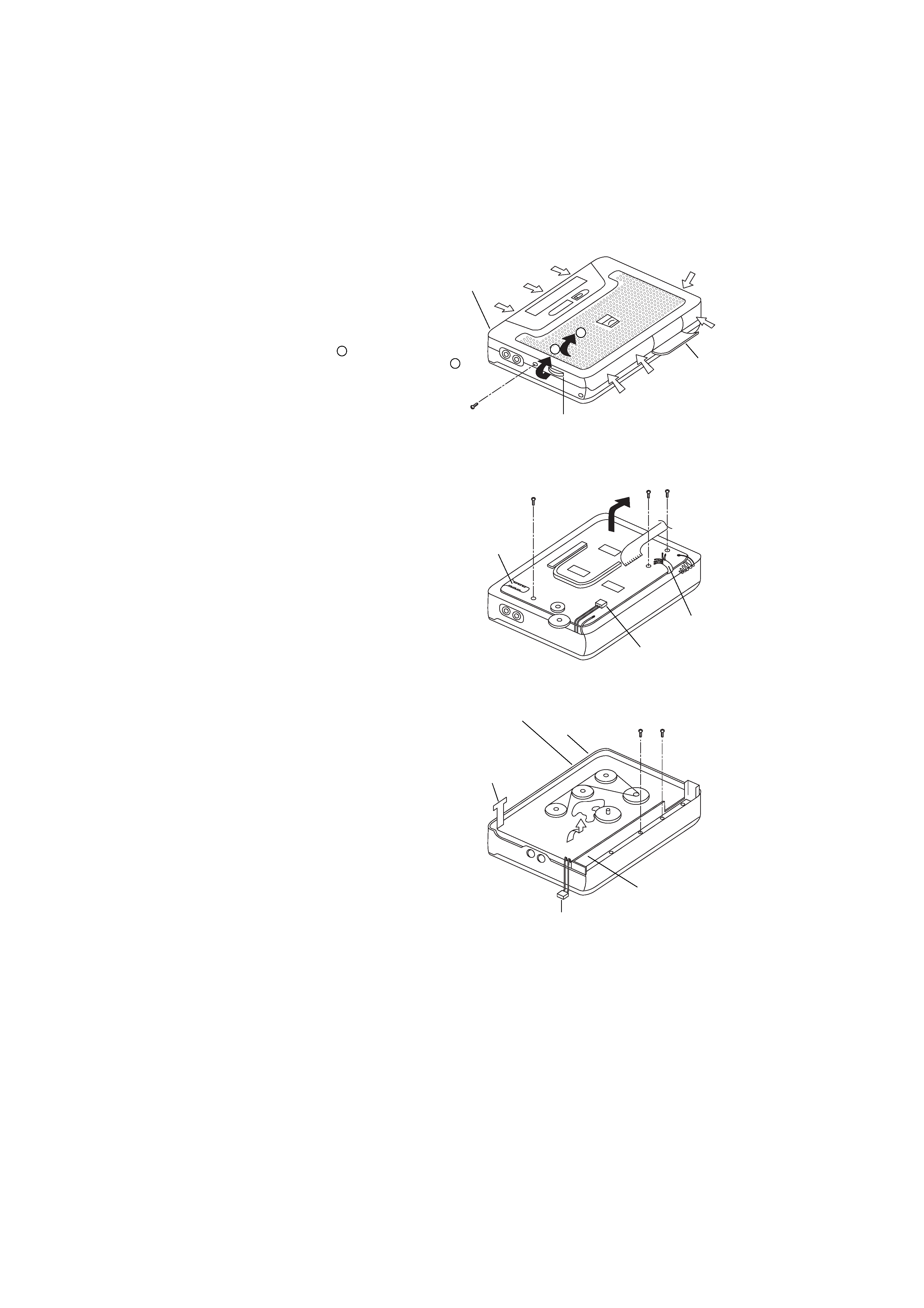
· REMOVAL OF REAR CABINET
1. Remove one screw on the Rear Cabinet.
2. Open the lid, battery.
3. Push in the direction of the white bold arrows to release all the
catches.
4. With the gap generated from the above step, slip in your finger
to remove the Rear Cabinet over the KNOB, RTRY TUN in the
direction of the black arrow A .
5. Remove the Rear Cabinet in the direction of black arrow B .
* A FLEX is soldered onto the board on the Rear Cabinet,
during disassembly, be careful not to damage this FLEX.
· REMOVAL OF THE MAIN C.B.
1. Remove 3 screws of the MAIN C.B.
2. Desolder the Tape Head FLEX and motor wires.
3. Disconnect the connector CON101.
4. Remove the MAIN C.B in the direction of the arrow.
· REMOVAL OF MECHANISM
1. Remove 2 screws of the HLDR, BAT.
2. Remove the mechanism in the direction of the bold arrow.
* During assembly of mechanism, be sure that connector
CON101 emerge out at the bottom as shown and the Direction
change switch and pause switch are engaged.
* CON101
Rear Cabinet
Battery Lid
KNOB, RTRY TUN
A
B
Desolder
Tape Head
FLEX
Desolder
Motor Wires
Disconnect
CON101
TO FRONT
C.B
MAIN C.B
Tape Head
FLEX
* Direction change switch
* Pause switch
HLDR, BAT
Rivision A4size.p65
9/24/98, 7:42 PM
3
4
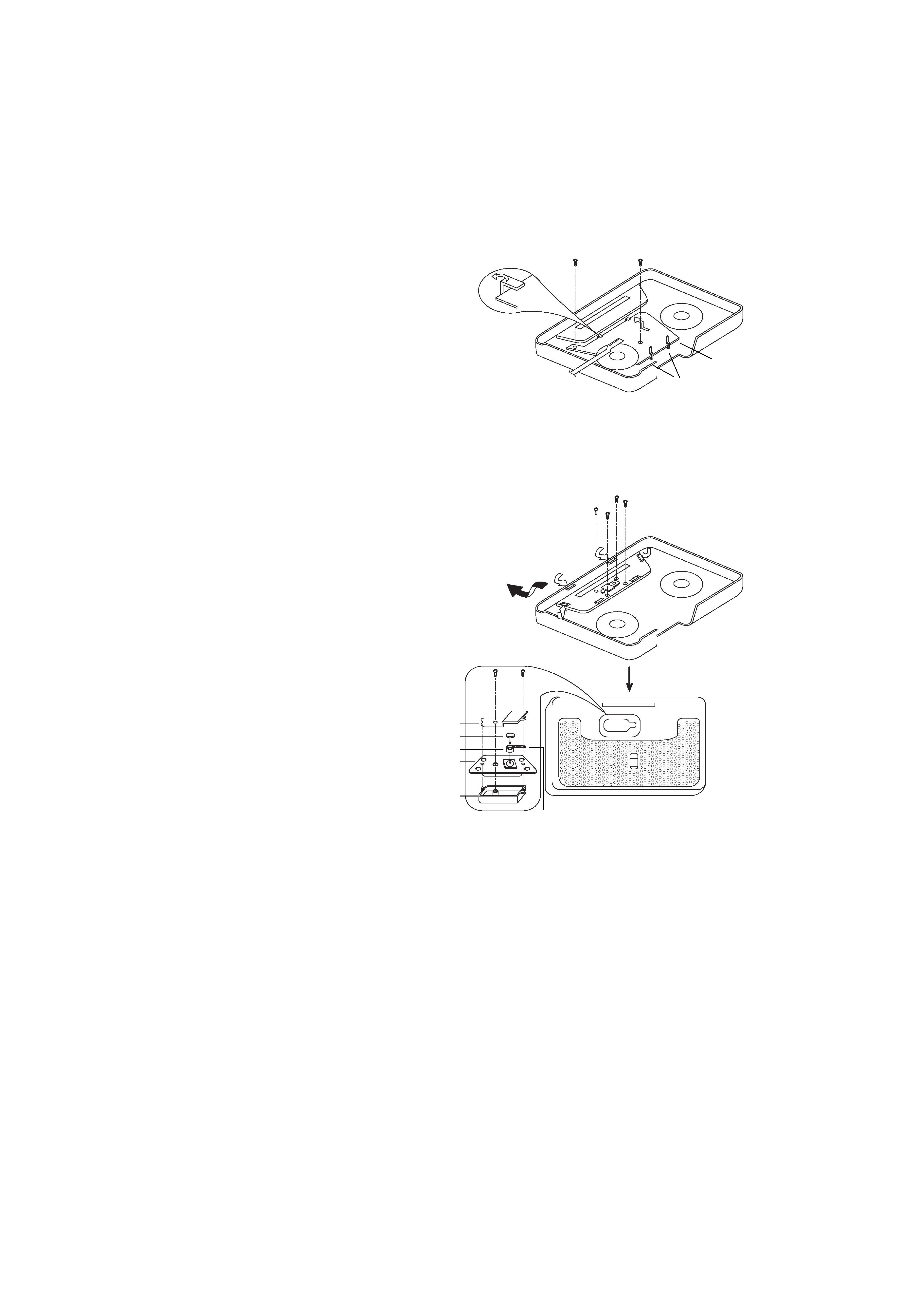
· REMOVAL OF THE FRONT C.B.
1. Remove 2 screws on the FRONT C.B.
2. Release the 2 hooks and slide the FRONT C.B out of the slots
in the direction of the arrow.
· REMOVAL OF THE BUILT-IN MIC
1. Remove 4 screws of the WINDOW, TUN.
2. Release the catches of the WINDOW, TUN by pushing in the
directions of white arrows.
3. Remove the WINDOW, TUN in the black arrow direction.
4. Remove 2 screws of the COVER, MIC.
5. Remove the COVER, MIC.
6. Remove the CUSHION, MIC.
7. Remove the NET, MIC and the HLDR, MIC and the
BUILT-IN, MIC can be removed.
FRONT
C.B
COVER, MIC
CUSHION, MIC
MIC
HLDR, MIC
NET, MIC
Ensure stress
free wires
Release
Hook
Slots
FRONT
C.B
FROM
MAIN C.B
Rivision A4size.p65
24-Sep-98, 10:58 AM
4
5
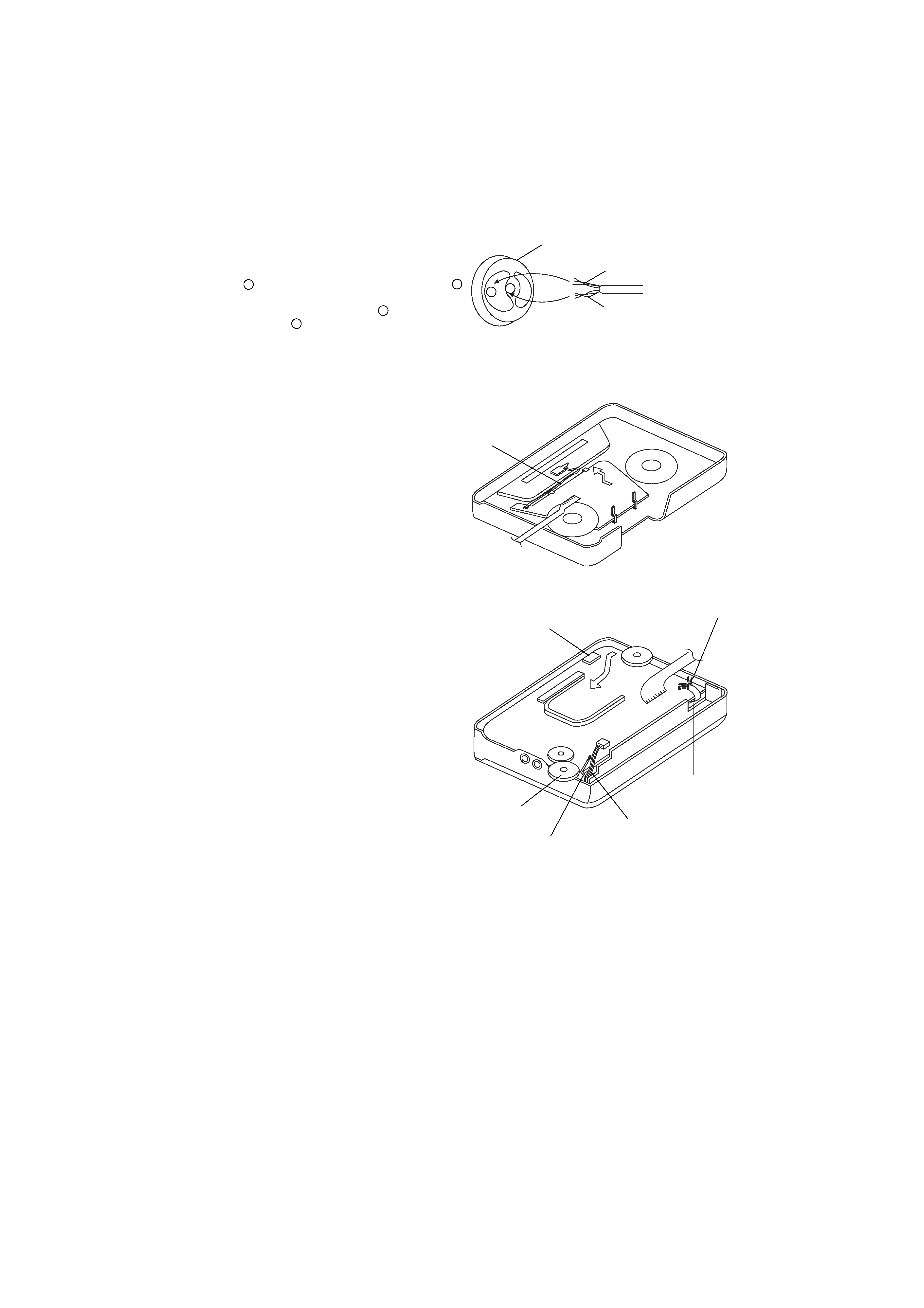
· HOW TO REPLACE THE BUILT-IN MIC
1. As shown illustration, the MIC has two solder points. One
point A is linked to the MIC CHASSIS and the other point B
is not.
Solder the GND wire (Black) to point A and the MIC wire
(Brown) to point B .
2. Place the MIC and CUSHION, MIC into the HLDR, MIC
make sure they are properly seated into the NET, MIC before
reassembling.
3. Arrange the MIC wires as shown so that it will not cause any
obstructions.
· REASSEMBLY OF MAIN BOARD
1. Slot in the MAIN C.B in the direction of the bold arrow.
2. Arrange the connector wires out through the hole and confirm
that it does not obstruct the KNOB, RTRY TUN and batteries
insertion.
3. Arrange the motor wires such that it does not obstruct SFR 51
and batteries insertion.
4. Confirm that pause switch is seated into the LEVER ASSY,
DIR.
MIC CHASSIS
MIC Wire
GND Wire
Back view of the MIC
MIC Wire
KNOB,
RTRY TUN
BAT, CONTACT (+)
Connector Wires
SFR 51
Motor Wires
Pause Switch
A
B
FRONT C.B
FROM
MAIN C.B
TO FRONT
C.B
MAIN C.B
Rivision A4size.p65
24-Sep-98, 10:58 AM
5