SERVICE MANUAL
DA
TA
COMPACT DISC
STEREO SYSTEM
BASIC TAPE MECHANISM : AZM-1 A2NM
BASIC CD MECHANISM : DA23LN
XR-M800
XR-M801
K
EZ
S/M Code No. 09-00B-437-1S1
SUPPLEMENT
· This Service Manual contains the additional information "DISASSEMBLY
INSTRUCTIONS" and "TEST MODE" for the model XR-M800/M801 (K,EZ).
If requiring the other information, see Service Manual of
XR-M800/801 (K,EZ), (S/M Code No. 09-00B-437-1R1).
XR-M800
SYSTEM
STEREO
RECEIVER
RX-LM800
REMOTE
CONTROLLER
RC-AAT22
CASSETTE DECK/
CD PLAYER
SPEAKER
XR-M801
RX-LM801
FD-LM800
FD-LM801
SX-LM810
-2-
DISASSEMBLY INSTRUCTIONS <FD-LM800/LM801>
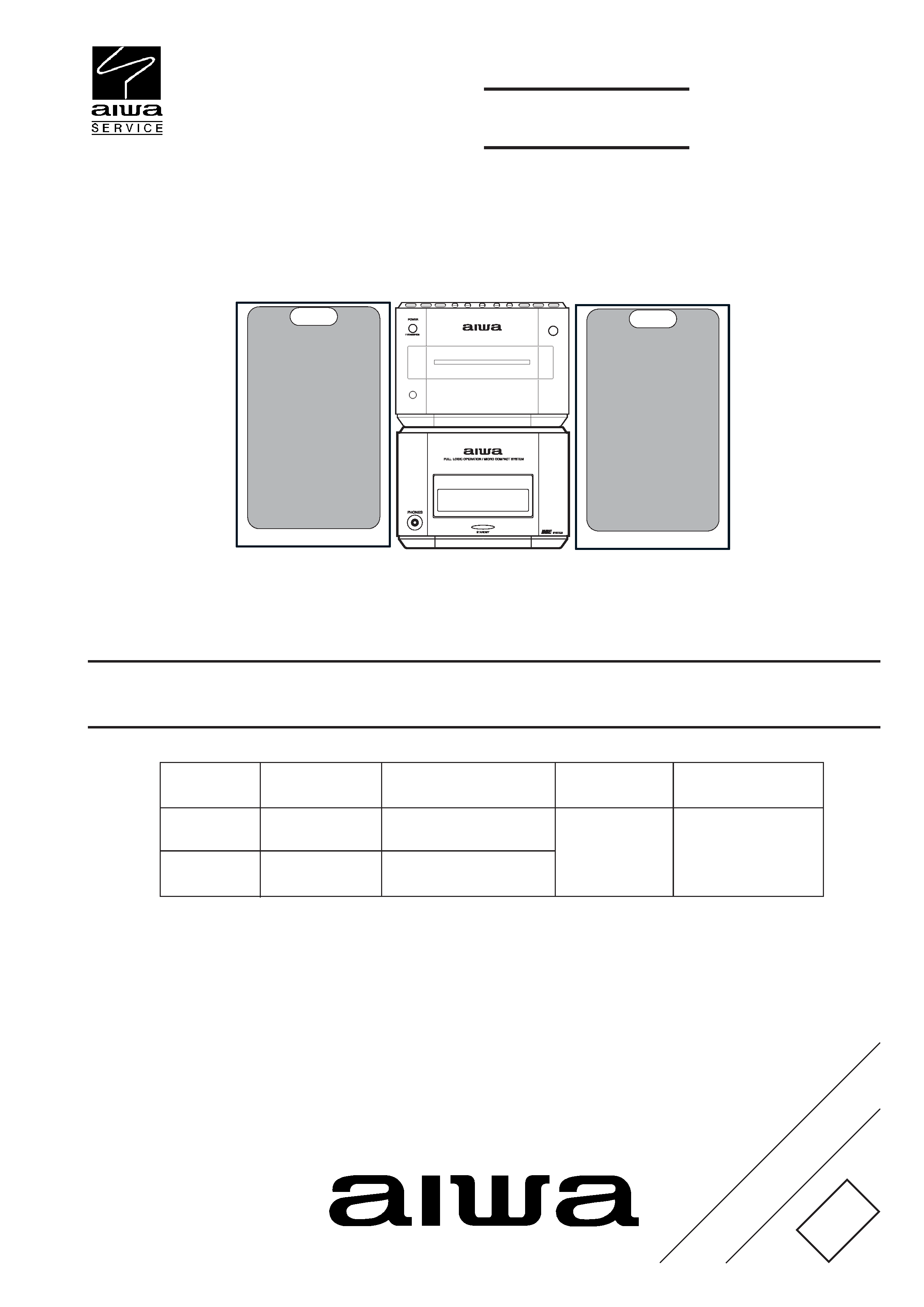
1. Removing the Ornament Parts
1)
Remove the two screws.
2)
Remove the two screws.
3)
Remove the eight screws 1 and remove the PANEL, REAR.
4)
Remove the FFC from the connector 1 and remove PANEL,
TOP 2.
-3-
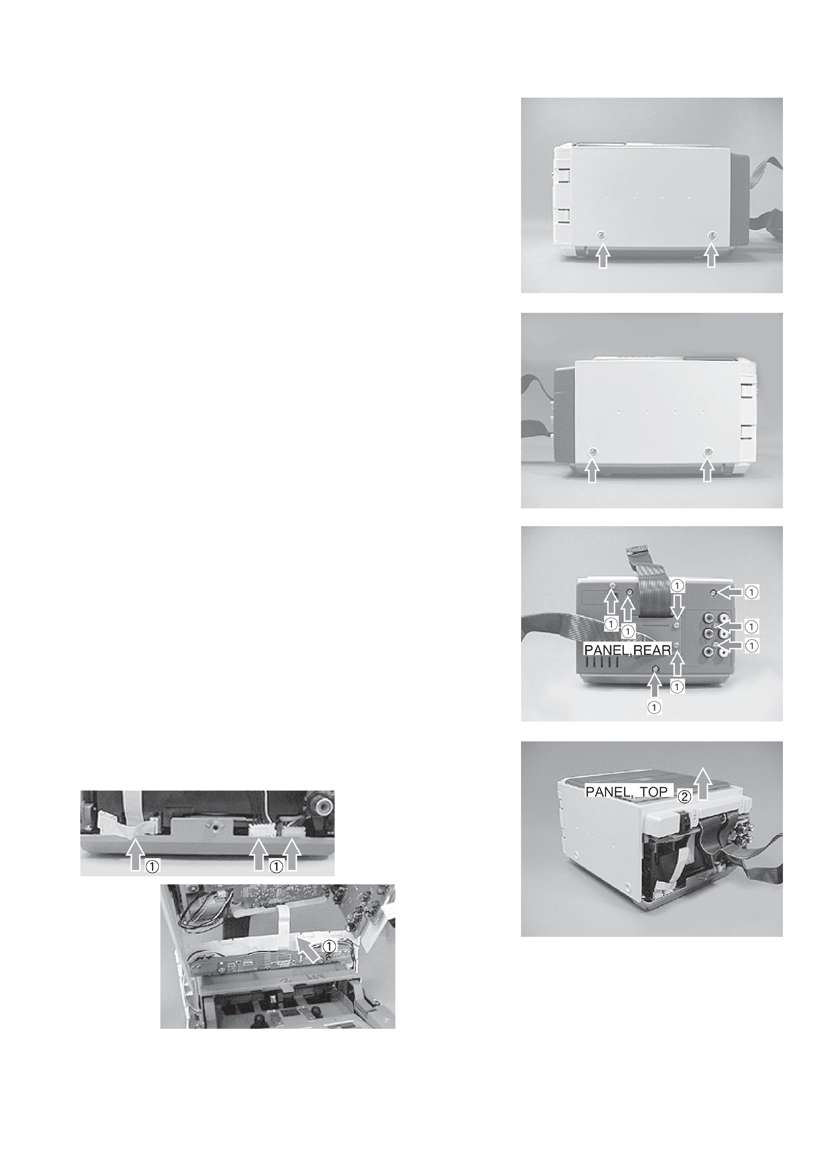
2. Removing the CD Block
1)
Remove the two screws and remove the entire CD block.
2)
The figure shows the status after the CD block is removed.
3. Removing the DECK Block
1)
Remove the screw.
2)
Remove the screw.
-4-
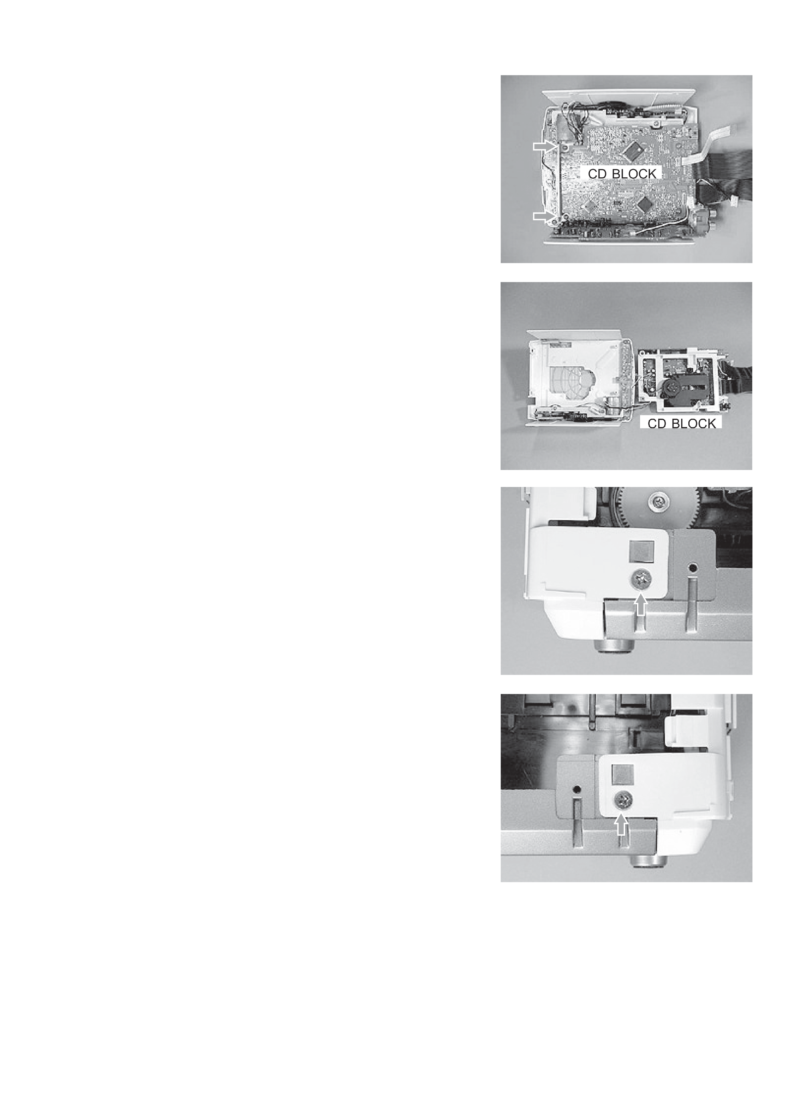
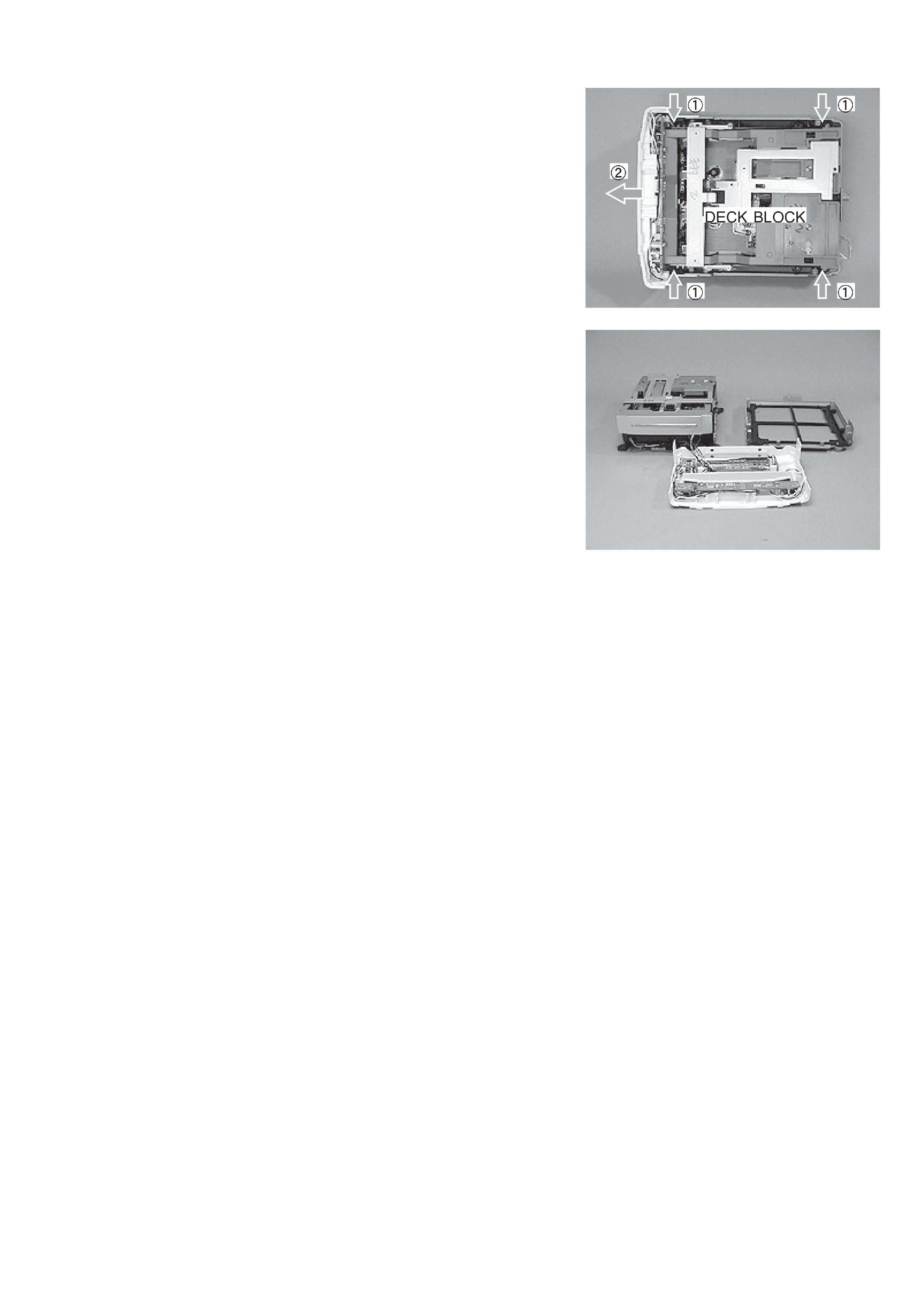
3)
Remove the four screws 1, remove the FRONT block 2 and
remove the DECK block.
4)
The figure shows the status after the DECK block is removed.
-5-
3. Function Descriptions and Application of the CD Test Mode
*1: The driver IC heats up and the protection circuit starts working when the focus search is continued for 10 minutes or longer. There can be a
case that operations cannot be performed correctly.
In such a case, turn off the main power. After cooling down the machine, restart the machine.
*2: Before performing the visual check of the lens operation, slightly open the CD lid by hand. If you press the OPEN button and open the CD
lid, the search mode exists.
*3: Be careful not to damage the gear because the sled motor rotates while the FF or REW button is being pressed even if the pick-up is located
in the innermost track or the outermost track.
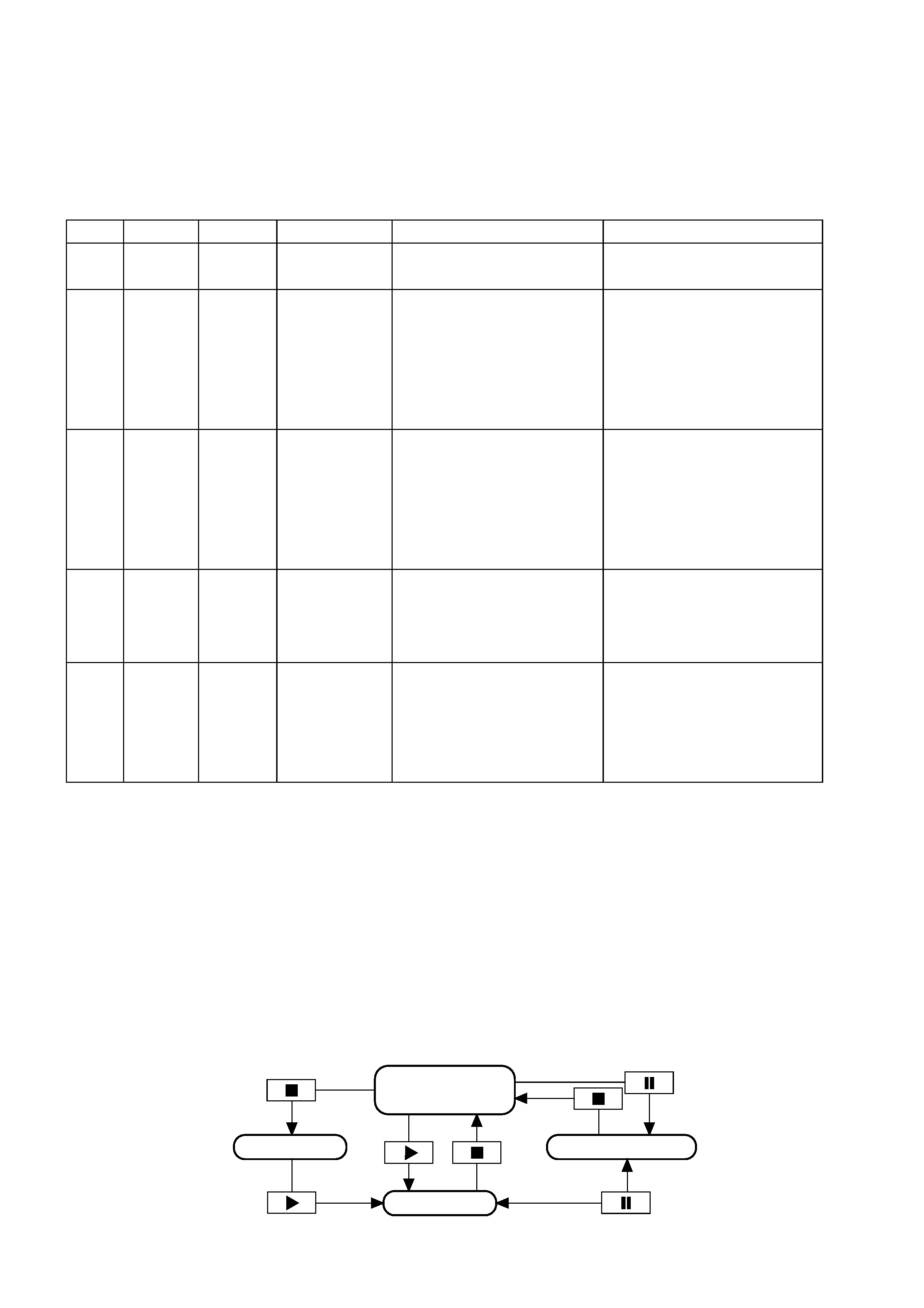
4. Overview of Operation
Each operation mode can be operated one mode after another using each button in the order starting from the "Start" mode that is shown by the
arrow mark in the illustration.
CD TEST MODE
1. How to Start the CD Test Mode
While pressing the function button, insert the AC plug to the
wall outlet. All the indicators on the display light, which means
that the test mode starts up.
2. How to Exit the CD Test Mode
Disconnect the AC plug.
Mode
Start mode
Search
mode
Play mode
Traverse
mode
Sled mode
Operation
9
1 2
;
5
6
FL indication
All indicators light
CD
Normal time
display
Normal time
display
CD TEST
Function
· FL lights
· Continuous focus search
*1 *2
· Normal playback
· If TOC cannot be read, focus
search of "2" is continued
· Tracking servo OFF/ON.
· Each time
; is pressed, the
tracking servo repeats turning
off/on.
· Pickup moves to the outermost
track *3
· Pickup moves to the innermost
track (normal operation during
playback)
Checking item
· Checking FL
· Checking microprocessor
· APC circuit
· Laser current
· Focus search waveform
· Focus error waveform
(FOK and FZC are not monitored
in the search mode)
· Focus servo
· Tracking servo
· Sled servo
· Spindle servo
· FOK
· RF waveform
· Tracking servo
· Traverse waveform
· Sled circuit
· Mechanism
No
1
2
3
4
5
Play mode
Start mode
All indicators light
Search mode
Traverse mode