D27U
S/M Code No. 09-986-264-4N3
SERVICE MANUAL
BASIC NAME
D27
NAME
P4LRN045B
P4ERN048C
N4ERN025C
N4ERN028C
DATA
English
VIDEO MECHANISM

2
TABLE OF CONTENTS
VCR TEST TAPE INTERCHANGEABILITY TABLE ................................................................................................................... 3
STANDARD MAINTENANCE ..................................................................................................................................................... 4
SERVICE JIGS AND TOOLS/ALIGNMENT TAPES FOR ADJUSTMENT ................................................................................. 5
FRONT LOADING MECHANISM DISASSEMBLY ................................................................................................................. 6-8
·
Front Loading Mechanism Assembly, Parts Location ...................................................................................................................................6
1.
Front Loading Mechanism Assembly .....................................................................................................................................................7
2.
Guide Cassette ....................................................................................................................................................................................... 7
3.
Bracket Assembly Side (R) ..................................................................................................................................................................... 7
4.
Bracket Side (L)/Top Plate ..................................................................................................................................................................... 7
5.
Holder Assembly Cassette ..................................................................................................................................................................... 8
6.
Arm Assembly F/L ..................................................................................................................................................................................8
7.
Spring Stopper ........................................................................................................................................................................................ 8
8.
Plate Reflector ........................................................................................................................................................................................ 8
DECK MECHANISM DISASSEMBLY ................................................................................................................................... 9-19
·
Deck Mechanism Parts Location ................................................................................................................................................................... 9
1.
Auto Head Cleaner Assembly ..............................................................................................................................................................10
2.
Drum and Base Assembly .................................................................................................................................................................... 10
3.
Drum Sub Assembly and Motor Assembly ........................................................................................................................................... 10
4.
A/C (Audio/Control) Head Assembly ................................................................................................................................................... 11
5.
FE (Full Erase) Head Assembly ........................................................................................................................................................... 11
6.
Plate Up/Supply Main Brake/Take up Main Brake/Body Prism Led Assembly ................................................................................... 11
7.
Tension Arm/Lever Assembly Tension ................................................................................................................................................. 12
8.
TAB Lever .............................................................................................................................................................................................12
9.
Supply Reel/Take Up Reel Assembly ...................................................................................................................................................12
10. Gear Pulley/Belt Capstan .....................................................................................................................................................................13
11. Gear H1, H2/Lever H1 ......................................................................................................................................................................... 13
12. Arm Assembly Idler ..............................................................................................................................................................................13
13. Mode S/W .............................................................................................................................................................................................13
14. Capstan Motor Assembly .....................................................................................................................................................................14
15. CAM Bracket Assembly ....................................................................................................................................................................... 14
16. Cam Bracket/Lever Jog/Gear Jog ........................................................................................................................................................ 14
17. Gear Cam L/D ......................................................................................................................................................................................14
18. Gear PS/Plate Slider ............................................................................................................................................................................ 15
19. Gear Assembly P2/P3 ......................................................................................................................................................................... 15
20. Base Assembly P2/P3 ......................................................................................................................................................................... 15
21. Guide Roller Assembly .........................................................................................................................................................................16
22. Clutch Assembly S27 ...........................................................................................................................................................................16
23. Clutch Assembly T27 ............................................................................................................................................................................ 16
24. Lever Assembly F/R & Arm F/R ........................................................................................................................................................... 16
25. Holder Pinch Assembly ....................................................................................................................................................................... 17
26. Pinch Arm Assembly ............................................................................................................................................................................ 17
27. L/D Motor Bracket Assembly ................................................................................................................................................................17
28. Worm Wheel .........................................................................................................................................................................................17
29. L/D Motor Assembly & Worm L/D Motor & L/D Motor Bracket ............................................................................................................. 18
30. Gear CNT .............................................................................................................................................................................................18
31. Gear Pinch ........................................................................................................................................................................................... 18
32. T/Up Arm Assembly ..............................................................................................................................................................................18
33. Gear Pinch Cam .................................................................................................................................................................................. 19
MECHANISM ADJUSTMENT ............................................................................................................................................. 20-30
1.
Mechanism and Mode Switch Alignment Check .................................................................................................................................. 20
2.
Preparation for Adjustment (To set VCR (VCP) to the loading state without inserting a cassette.) .................................................... 21
3.
Tension Post Position and Tension Adjustment ...................................................................................................................................21
4.
Checking Torque ..................................................................................................................................................................................22
5.
Guide Roller Height Adjustment ........................................................................................................................................................... 23
6.
Audio/Control (A/C) Head Adjustment ........................................................................................................................................... 24, 25
7.
X-Value Adjustment ..............................................................................................................................................................................25
8.
Adjustment after Replacing Drum Assembly (Video Heads) .................................................................................................................................................... 26
9.
Check the Tape Travel after Reassembling Deck Assembly ........................................................................................................................................................... 26, 27
10. Maintenance/Inspection Procedure ................................................................................................................................................ 28-30
EXPLODED VIEW .............................................................................................................................................................. 31-33
PARTS LIST .............................................................................................................................................................................. 34
REFERENCE NAME LIST ........................................................................................................................................................ 35
3
VCR TEST TAPE INTERCHANGEABILITY TABLE
There are two types of the new allgnment tape CH-1B (for NTSC) and CH-2 (for PAL). On each tape four signals (1)-(4)
are recorded for the times and in the order shown below.
(1) : 8min.
(2) : 2min.
(3) : 5min.
(4) : 5min.
The TTV-MP1 (for M-PAL), TTV-MS1 (for MESECAM) and TTV-S1 (for SECAM) allgnment tapes have the same
contents as the previous tapes.
* 1. Described in the order of color format. video signal. linear audio. tape speed and Hi-Fi audio.
* 2. Use CH-1B (1)-(3) with models used exclusively in the SP mode.
* 3. Use CH-2 (3) and (4) when it is necessary to observe the chroma signal.
Method
Now in use TYPE
Model
Contents *1
New TYPE
Model
Contents *1
Application
NTSC
PAL
TTV-N1
NTSC, Color bar,
1kHz, SP
TTV-NS1
NTSC, Color bar,
1kHz, SP
TTV-N1E
NTSC, Color bar,
1kHz, EP
TTV-NS6E
NTSC, Color bar,
No sound, EP
TTV-N2
NTSC, Stairsteps,
7kHz, SP
TTV-N12
(SCV-1998)
NTSC, Color bar,
1kHz, SP
NTSC, Mono scope,
7kHz, SP
TTV-N7A
NTSC, Stairsteps,
1kHz, SP, HiFi 400Hz
TTV-N6
(TTV-N06T)
TTV-P1
PAL, Color bar,
1kHz, SP
TTV-P1L
PAL, Color bar,
1kHz, LP
TTV-P2
PAL, Stairsteps,
6kHz, SP
PAL, Monoscope,
6kHz, SP
TTV-P6
(TTV-N06T)
TTV-P7
PAL, Stairsteps,
1kHz, SP,
HiFi 1kHz
TTV-P16
PAL, Color bar,
400Hz,
SP, HiFi 1kHz
CH-1B(2)
NTSC, Stairsteps,
1kHz, SP
No Changed.
NTSC, Color bar,
1kHz, EP
CH-1B(4)
*2
No Changed.
CH-1B(1)
NTSC, Stairsteps,
7kHz, SP
CH-1B(4)
NTSC, Color bar,
1kHz, EP
No Changed.
CH-1B(3)
NTSC, Color bar,
No sound SP,
HiFi 400Hz
PAL, Stairsteps,
1kHz, SP
CH-2(2)
* 3
CH-2(4)
PAL, Color bar,
1kHz, LP
CH-2(1)
PAL, Stairsteps,
6kHz, SP
No Changed.
CH-2(3)
PAL, Color bar,
No sound
SP, HiFi400Hz
No Changed.
PB-Y Level/General electrical ADJ.
Head ACE Height/Tilt ADJ.
For S-VHS (SQPB) check
Switching position ADJ.
For S-VHS (SQPB) check
Head ACE Azimuth ADJ.
FM Envelope ADJ.
X-Value ADJ.
For total picture quality check (resolution, etc)
HiFi Audio PB Level ADJ.
Switching position ADJ.
PB-Y Level/General electrical ADJ.
Head ACE Height/Tilt ADJ.
Switching position. (LP Model)
FM Envelope ADJ. (LP Model)
X-Value ADJ. (LP Model)
HEAD ACE Azimuth ADJ.
FM Envelope ADJ. (SP Model)
X-Value ADJ. (SP Model)
For total picture quality check (resolution, etc)
FM Filter ADJ.
HiFi Audio PB Level ADJ.
4
STANDARD MAINTENANCE
1. SERVICE SCHEDURE
The standard list is shown as follows which is heavily
dependent on the environmental conditions and operating
method. If maintenance is not properly executed, the
problem will grow over time into other parts of the machine
which will shorten the maintenance period as shown in the
list. If the machine is not used for long period of time or
incorrectly used, the rubber parts can be deformed and worn
out of their lives. The following list shows a reference time
for maintenance and can differ from actual time of the
required maintenance.
2. CLEANING
Note:
·
If a part is cleaned using alchol, dry it completely before
tape is run in the mechanism. If drying is incomplete,
alchol will stick on the tape and will damage that portion
of the tape.
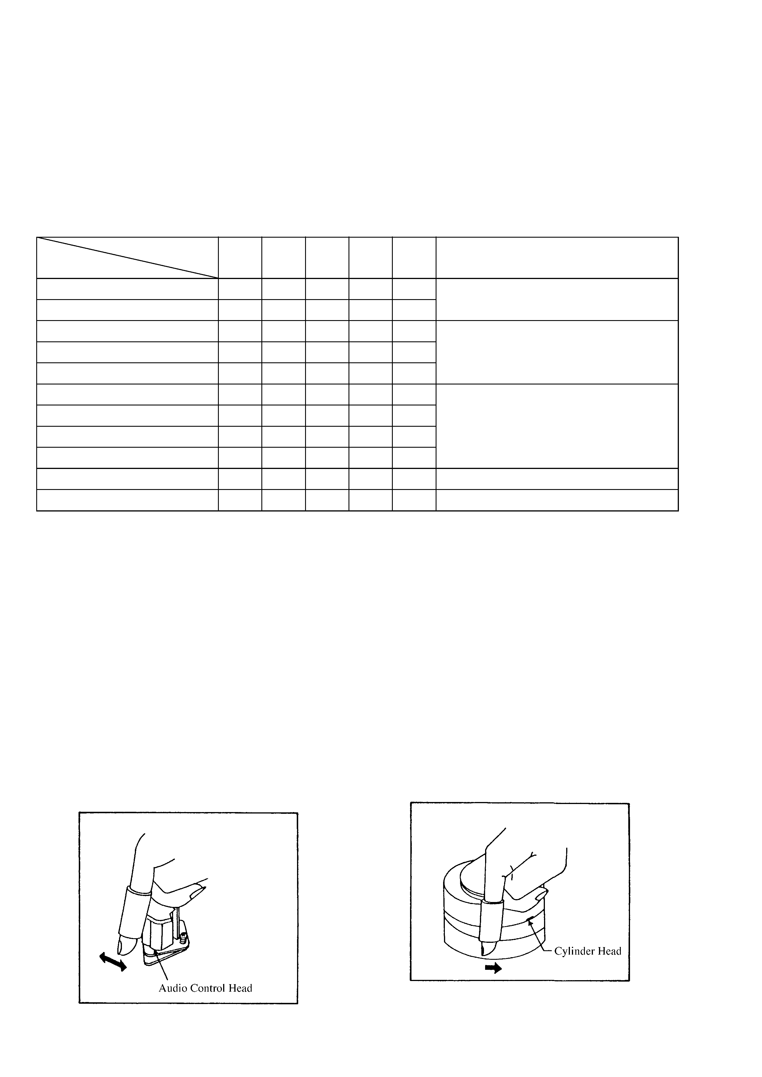
(1) Audio Control Head
·
Wrap the cleaning cloth or chamois around finger and
soak it with alcohl. Move it horizontally over the audio
control head. Clean the full erase head in the same way.
(See the illustration below.)
(2) Tape Run Mechanism
·
Clean the tape run mechanism with gauze soaked with
alchol.
0: Replace
9: Cleaning
Inspection Time
Parts Name
Audio Control Head
Full Erase Head
Reel Belt
Front Loading Belt
Pinch Roller
Capstan DD Unit
Loading Motor
Tension Band Ass'y
Capstan Shaft
Tape Run Mechanism Guide Posts
Cylinder Unit
Notes
Clean the parts which contact tape.
Clean the rubber parts and the parts which
contact rubber.
If abnormal rotation is found, replace it.
Clean the heads.
500
Hours
9
9
9
9
9
9
1,000
Hours
9
9
9
9
9
9
9
9 0
1,500
Hours
9
9
9
9
9
9
2,000
Hours
9
9
0
0
9
9
9
9 0
3,000
Hours
9
9
9 0
0
0
0
9
9
9 0
(3) Cylinder
·
Put on glove (thin glove) so that the upper drum or
lower drum must be touched by naked hand.
·
Apply a few drops of alchol into the cleaning cloth or
chamois. Bring it in contact with the head tip and rotate
the upper drum in the counterclockwise direction.
Note:
·
Though the video head is made from the very hard
material, it is very thin and fragile. Never move the
cleaning cloth or chamois in vertical direction or clean it
vertically. It can easily break the head.
·
Do not operate the machine before the cleaned portion is
completely dried.
·
The stained chamois or the stained head cleaning cloth
must not be re-used.
5
ALIGNMENT TAPES FOR ADJUSTMENT
Derivation No.
A
B
C
D
Mechanism
PAL
PAL
NTSC
NTSC
SP/LP
SP
SP/LP/EP
SP
Adjustment Items
2/4 Head
2 Head
2/4 Head
2 Head
FM Envelope
TTV-P2L
TTV-P2
TTV-N1
TTV-N2
(TTV-N12)
Slantness
A commercially available tape
A/C
TTV-P1
TTV-N1
TTV-N1
Head
Height
(TTV-P1L)
TTV-P1
(TTV-N12)
(TTV-N12)
(TTV-N1E)
Azimuth
TTV-P2
TTV-P2
TTV-N2
TTV-N2
TTV-P2
TTV-N2
X-value
(TTV-P2L)
TTV-P2
TTV-N2E
TTV-N2
TTV-N12
RG Post Inclination
A commercially available tape
Tape Back Tension
SRK-VHT-103
*
The numbers in ( ) parenthesis can be used as the substitute.
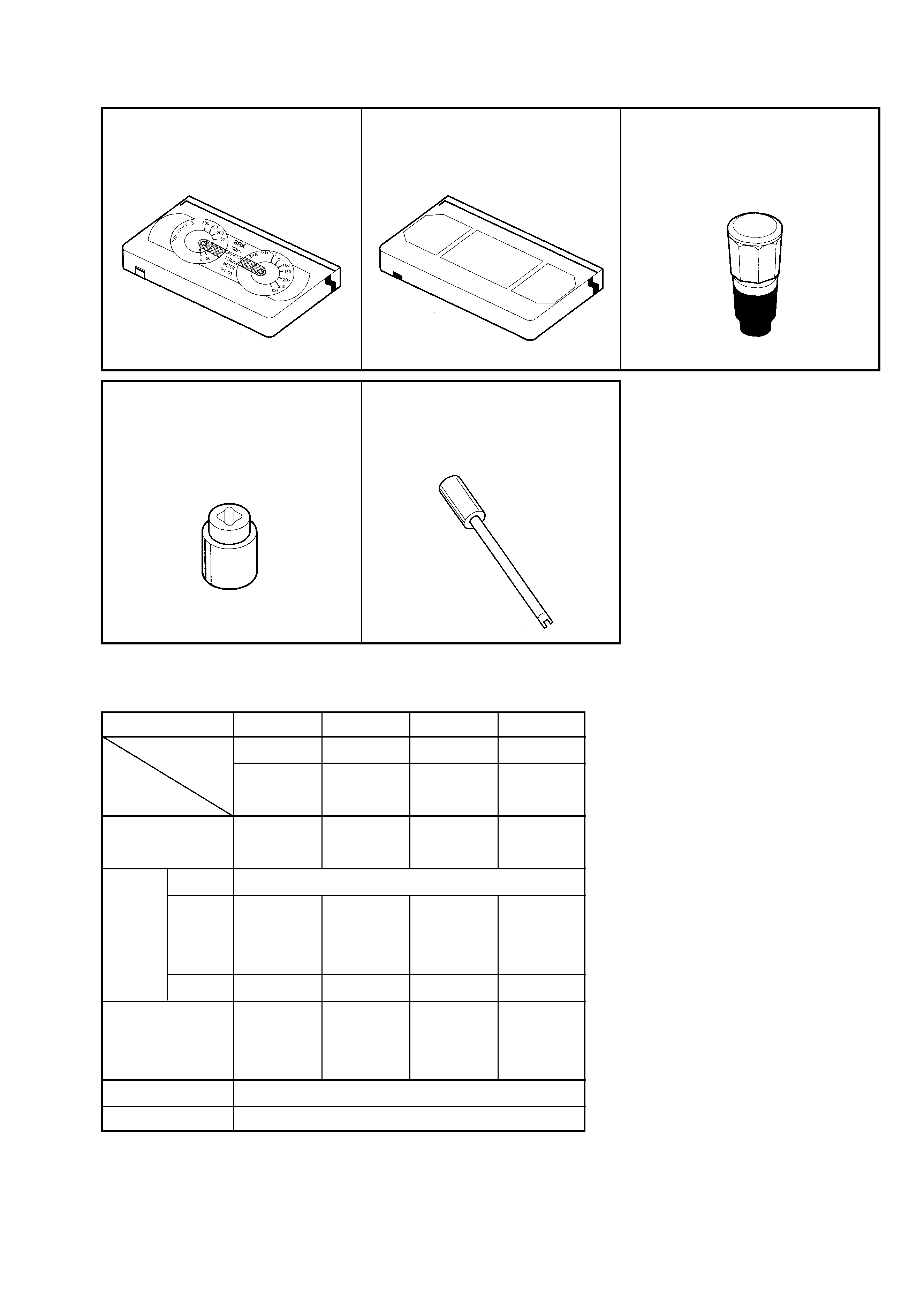
1. Cassette Torque meter
2. Alignment tape
3. Torque gauge
Parts No: SRX-VHT-103
(See figure below)
Parts No: D00-D002
4. Torque gauge adaptor
5. Post height adjusting driver
Parts No: D09-R001
Parts No:
SV-TG0-030-000 (SMALL)
SV-TG0-020-000 (LARGE)
SERVICE JIGS AND TOOLS
·
Tools and Fixtures for Deck