
CT-X410 YU
STEREO CAR CASSETTE RECEIVER
RADIO-CASSETTE ESTEREOFONICO PARA AUTOMOVIL
d
OPERATING INSTRUCTIONS
MANUAL DE INSTRUCCIONES
MODE D'EMPLOI
OWNER'S RECORD
For your convenience, record the model number and
serial number (you will find them on the right side of
your set) in the space provided below. Please refer to
them when you contact your AIWA dealer in case of
difficulty.
Model No. CT-X410
Serial No.
ENGLISH
ESPAÑOL
FRANÇAIS
CTX410(YU)-total-En-2
Welcome
Thank you for your purchasing this AIWA product.
To optimize the performance of this unit, please
read through this manual carefully.
In addition to this operating instructions manual,
be sure to refer to the separate installation and
connections manuals as well.
PRECAUTIONS
· This unit is designed to be operated on a 12-volt
DC negative-ground electrical system only.
· To prevent short-circuiting, disconnect the
negative car battery terminal until the unit has
been mounted and connected completely.
· When replacing the fuse, be sure to use one
whose amperage rating is identical. Use of a
fuse of higher amperage may cause serious
damage to the unit.
· Keep screwdrivers, etc. and other metallic or
magnetic objects away from the playback head.
· When your car was parked in direct sunlight
resulting in a considerable rise in temperature
inside the car, allow the unit to cool off before
operating it.
· Keep the volume at such a level that you can
hear outside warning sounds (horns, sirens,
etc.).
Notes on cassettes
Do NOT expose cassettes to direct sunlight,
extremely high or cold temperature or moisture.
Keep cassettes away from equipment with built-
in magnets to avoid unwanted noise or loss of
sound quality.
Do NOT touch the tape of a cassette, as any dirt
or dust will contaminate the heads.
Be sure to remove any cassette from the unit if
you are not using it.
NOTE
This equipment has been tested and found to
comply with the limits for a Class B digital device,
pursuant to Part 15 of the FCC Rules. These
limits are designed to provide reasonable
protection against harmful interference in a
residential installation.
This equipment generates, uses, and can radiate
radio frequency energy and, if not installed and
used in accordance with the instructions, may
cause
harmful
interference
to
radio
communications. However, there is no guarantee
that interference will not occur in a particular
installation. If this equipment does cause harmful
interference to radio or television reception, which
can be determined by turning the equipment off
and on, the user is encouraged to try to correct
the interference by one or more of the following
measures:
-- Reorient or relocate the receiving antenna.
-- Increase the separation between the
equipment and receiver.
-- Connect the equipment into an outlet on
circuit different from that to which the
receiver is connected.
-- Consult the dealer or an experienced radio/
TV technician for help.
CAUTION
Modifications or adjustments to this product, which
are not expressly approved by the manufacturer,
may void the user's right or authority to operate
this product.
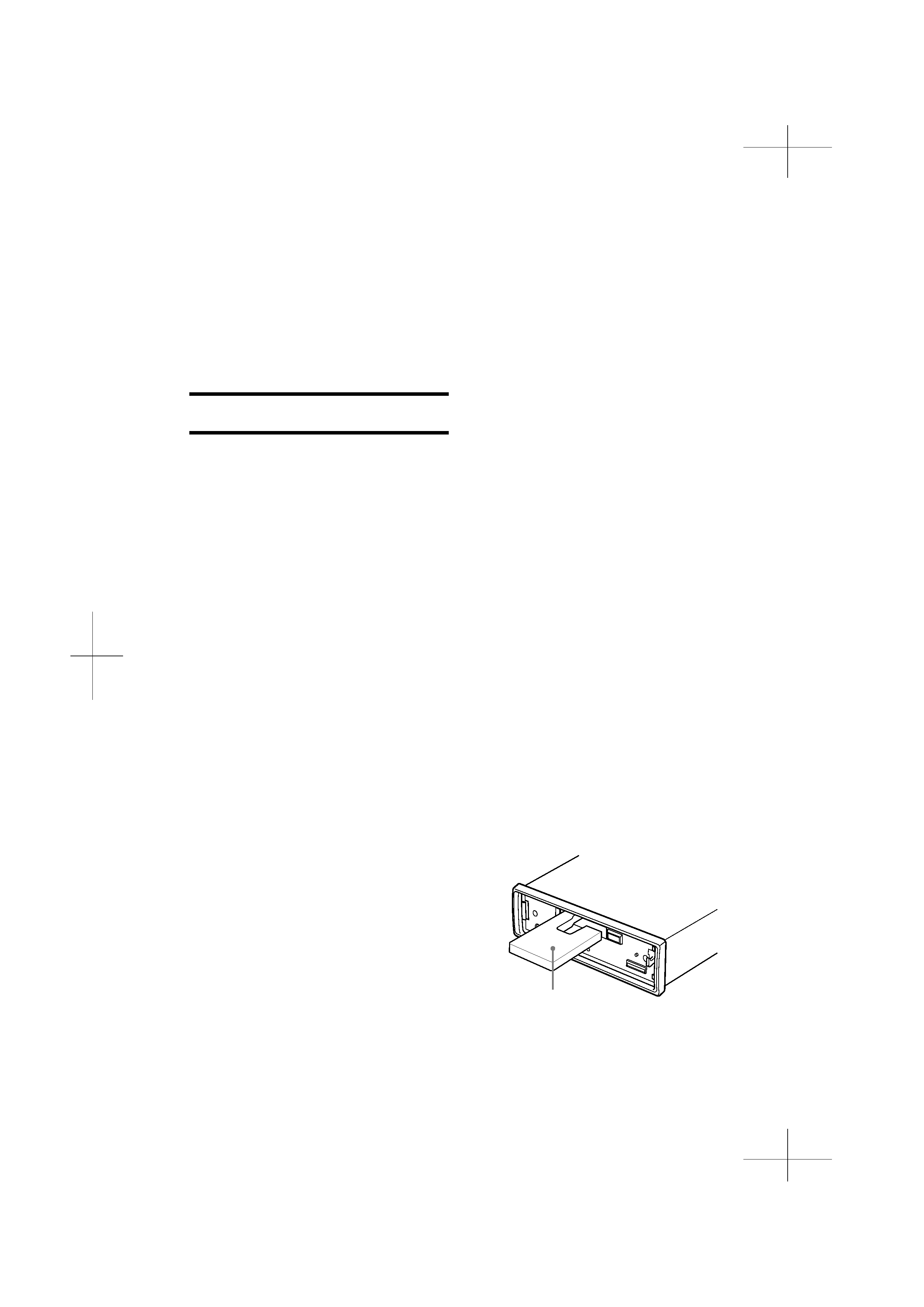
Caution on the transit protection pad
The unit is shipped with a transit protection pad
in the cassette compartment.
Be sure to press EJECT
z to remove the pad
before operating the unit.
1 ENGLISH
Transit protection pad

CTX410(YU)-total-En-3
TABLE OF CONTENTS
PARTS AND CONTROLS .................................................................................................................. 3
DETACHING AND ATTACHING THE FRONT PANEL ...................................................................... 4
SETTING THE CLOCK ....................................................................................................................... 5
RADIO OPERATION .......................................................................................................................... 5
PRESETTING STATIONS .................................................................................................................. 6
MY INFORMATION SWITCH ............................................................................................................. 8
TAPE PLAYBACK ............................................................................................................................... 9
SOUND ADJUSTMENTS ................................................................................................................. 10
CONNECTING A PORTABLE CD/MD/MP3 PLAYER OR OTHER EQUIPMENT ........................... 12
SETTING THE BEEP TONE ............................................................................................................. 13
MAINTENANCE ................................................................................................................................ 13
SPECIFICATIONS ............................................................................................................................ 14
ENGLISH
ENGLISH
2
CTX410(YU)-total-En-4
3 ENGLISH
Display window
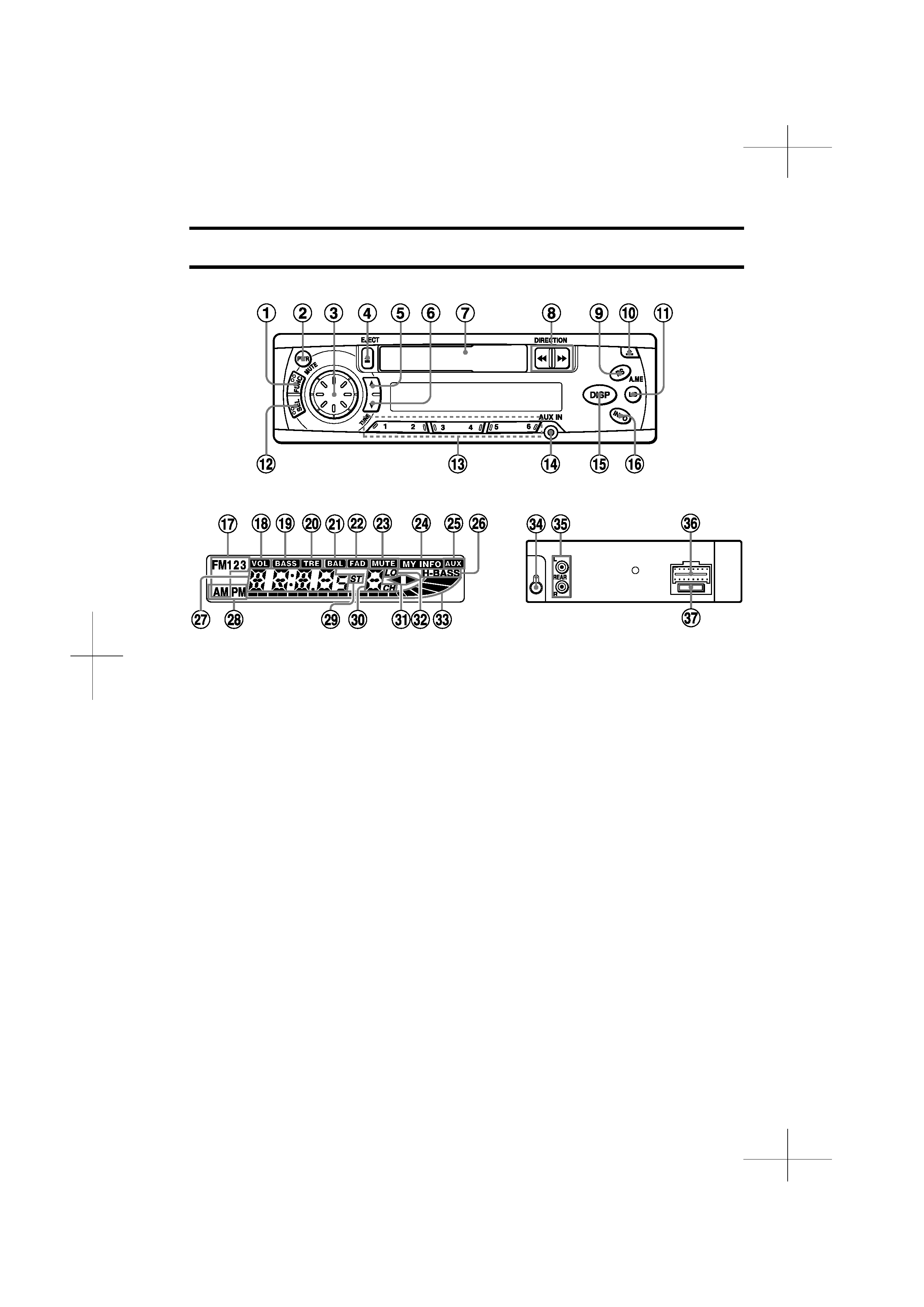
PARTS AND CONTROLS
Rear panel
Front panel
Front panel
1 FUNC (function) button
2 PWR (power on/off)/MUTE button
3 Jog Dial
4 z (eject) button
5 TUNE i button
6 TUNE k button
7 Cassette compartment
8 DIRECTION f/g button
9 A.ME (Auto Memory)/PS (Preset Scan)
button
0 % (release) button
! LO (local) button
@ SEL (select) button
# Preset station buttons (1 6)
$ AUX IN jack (3.5-mm dia.)
% DISP (display) button
^ INFO (My Information) button
Display window
& Band indicator
* VOL (volume) indicator
( BASS (bass) indicator
) TRE (treble) indicator
- BAL (balance) indicator
= FAD (fader) indicator
q MUTE indicator
w MY INFO (My Information) indicator
eAUX indicator
r H-BASS (High BASS) indicator
t Main display section
y AM/PM (clock) indicator
u ST (stereo) indicator
i Subdisplay section
o d (tape direction) indicators
p LO (local) indicator
[ Audio level indicator
Rear panel
] Antenna jack
\ REAR preout jacks
a Power supply/speaker connector
s Fuse
CTX410(YU)-total-En-5
ENGLISH
4
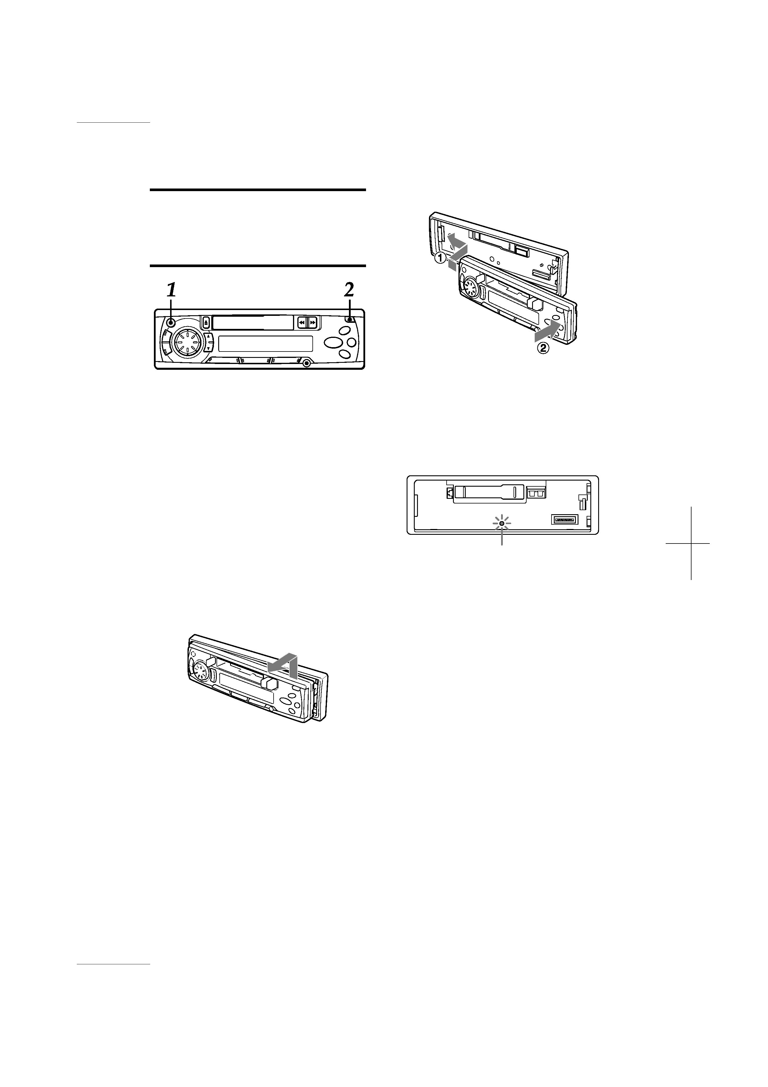
DETACHING AND
ATTACHING THE FRONT
PANEL
You can detach the front panel from the unit and
carry it with you when you leave your car
unattended.
When you carry the front panel out of your car,
use the supplied carrying case.
Before detaching the front panel, remove the
cassette to prevent possible damage to the unit.
1 Press and hold PWR for more than 2
seconds to turn the unit off.
2 While supporting the front panel with
one hand, press
% to release one side
of the panel. Care must be taken not to
drop the panel. It may suddenly become
detached at this point.
3 When the front panel is lifted from the
unit, remove it by pulling it away from
the unit.
Do NOT touch the connector on the reverse
side of the front panel, as doing so may
contaminate the connector and cause poor
connection, resulting in a malfunction.
Attaching the front panel
Security Lamp
When the front panel is detached, you can find an
LED lamp on the front side of the unit. This lamp
is designed to deter theft, and continues to flash
when the front panel is detached. This unit is not
equipped with any other security system, such as
a security alarm, so there are limitations to its
effectiveness.
LED lamp