MD MECHANISM
AZG-W
S/M Code No. 09-022-355-9N4
English
SERVICE MANUAL
BASIC MD MECHANISM : AZG-L
DA
TA
TYPE
AM
YAM
A1F
YA1F
A1M
YA1M
YA1K
BASIC MD MECHANISM
AZG-L ANM
AZG-L ANM
AZG-L ANF
AZG-L ANF
AZG-L ANM
AZG-L ANM
AZG-L AK
-2-
PROTECTION OF EYES FROM LASER BEAM DURING SERVICING
VAROITUS!
Laiteen Käyttäminen muulla kuin tässä käyttöohjeessa mainit-
ulla tavalla saattaa altistaa käyt-täjän turvallisuusluokan 1 ylit-
tävälle näkymättömälle lasersäteilylle.
VARNING!
Om apparaten används på annat sätt än vad som specificeras i
denna bruksanvising, kan användaren utsättas för osynling
laserstrålning, som överskrider gränsen för laserklass 1.
Caution: Invisible laser radiation when
open and interlocks defeated avoid expo-
sure to beam.
Advarsel:Usynling laserståling ved åbning,
når sikkerhedsafbrydere er ude af funktion.
Undgå udsættelse for stråling.
CAUTION
Use of controls or adjustments or performance of procedures
other than those specified herein may result in hazardous
radiation exposure.
ATTENTION
L'utilisation de commandes, réglages ou procédures autres que
ceux spécifiés peut entraîner une dangereuse exposition aux
radiations.
ADVARSEL!
Usynlig laserståling ved åbning, når sikkerhedsafbrydereer ude
af funktion. Undgå udsættelse for stråling.
This Compact Disc player is classified as a CLASS 1 LASER
product.
The CLASS 1 LASER PRODUCT label is located on the rear
exterior.
This set employs laser. Therefore, be sure to follow carefully the
instructions below when servicing.
WARNING!
WHEN SERVICING, DO NOT APPROACH THE LASER EXIT
WITH THE EYE TOO CLOSELY. IN CASE IT IS NECESSARY TO
CONFIRM LASER BEAM EMISSION. BE SURE TO OBSERVE
FROM A DISTANCE OF MORE THAN 30cm FROM THE
SURFACE OF THE OBJECTIVE LENS ON THE OPTICAL
PICK-UP BLOCK.
CLASS 1
KLASSE 1
LUOKAN 1
KLASS 1
LASER PRODUCT
LASER PRODUKT
LASER LAITE
LASER APPARAT
-3-
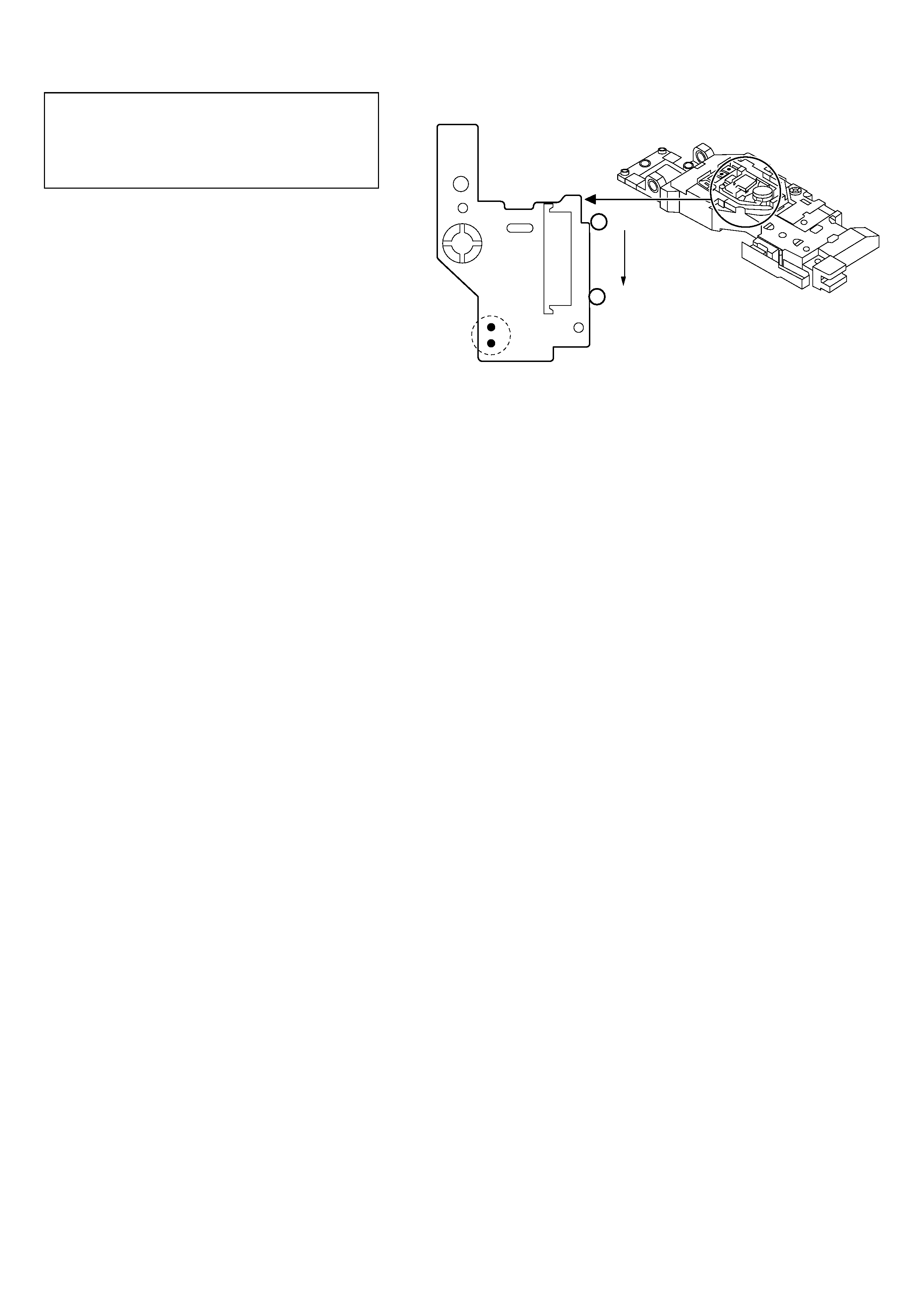
Precaution to replace Optical block
(KSM-260E)
1) After the connection, remove solder shown in
the right figure.
Body or clothes electrostatic potential could ruin
laser diode in the optical block. Be sure ground
body and workbench, and use care the clothes
do not touch the diode.
VEE
¡ TRK
Pattern side
Solder
MD PICKUP Assy PWB
1
21
-4-
Fig.1-1
Fig.1-2
Fig.2
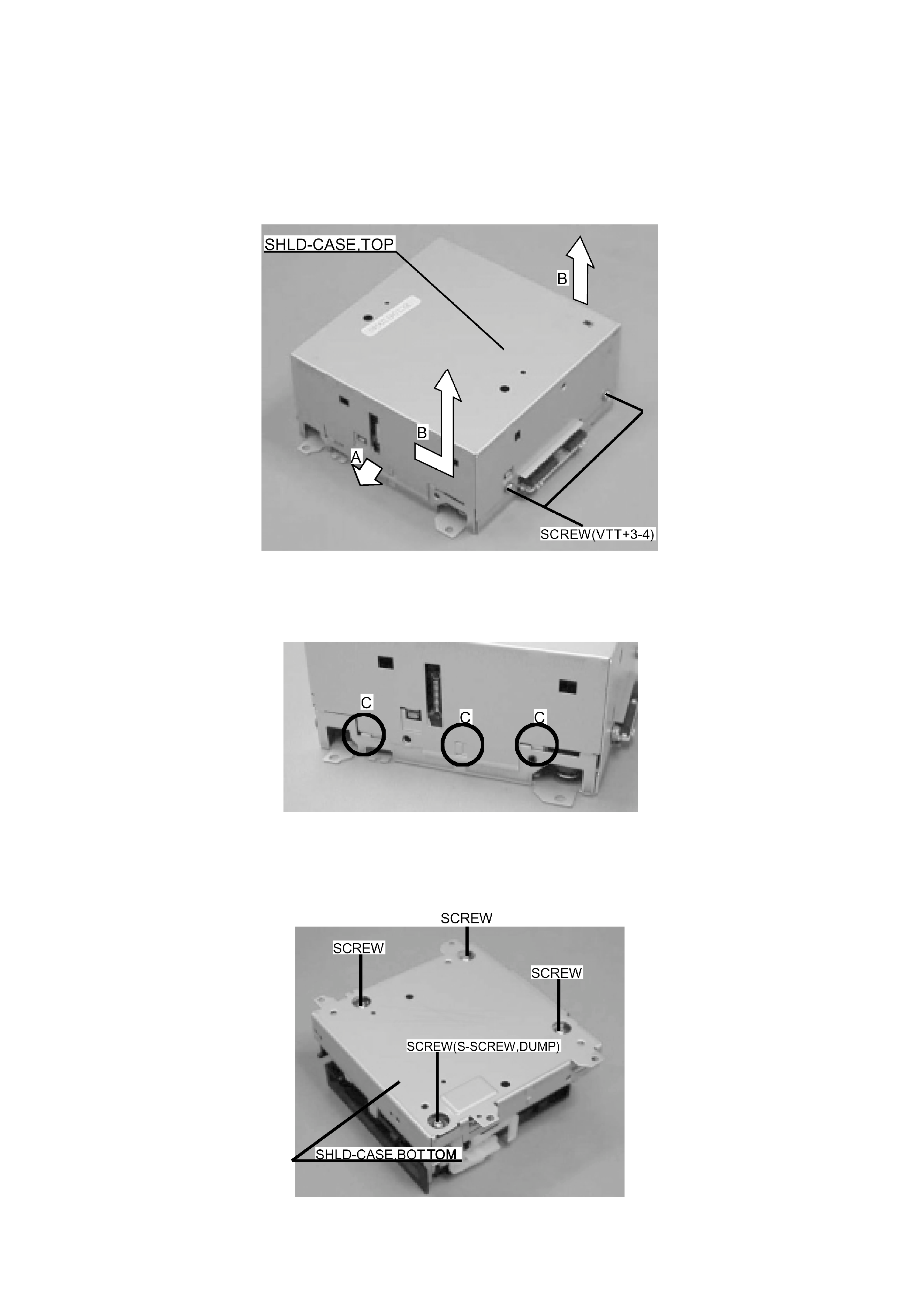
DISASSEMBLY INSTRUCTIONS-1/6
NOTES FOR DISASSMBLING AND ASSEMBLING MD MECHANISM
1. SHLD-CASE, TOP
1)
Remove the two screws (VTT+3-4).
2)
Remove the SHLD-CASE, TOP in the direction of the arrow B while opening the SHLD-CASE, TOP in the direction of the arrow A.
Note for assembling
Ensure that the three positions circled by round C are engaged securely.
2. SHLD-CASE, BOTTOM
1)
Remove the four screws (S-SCREW, DUMP) and remove the SHLD-CASE, BOTTOM.
-5-
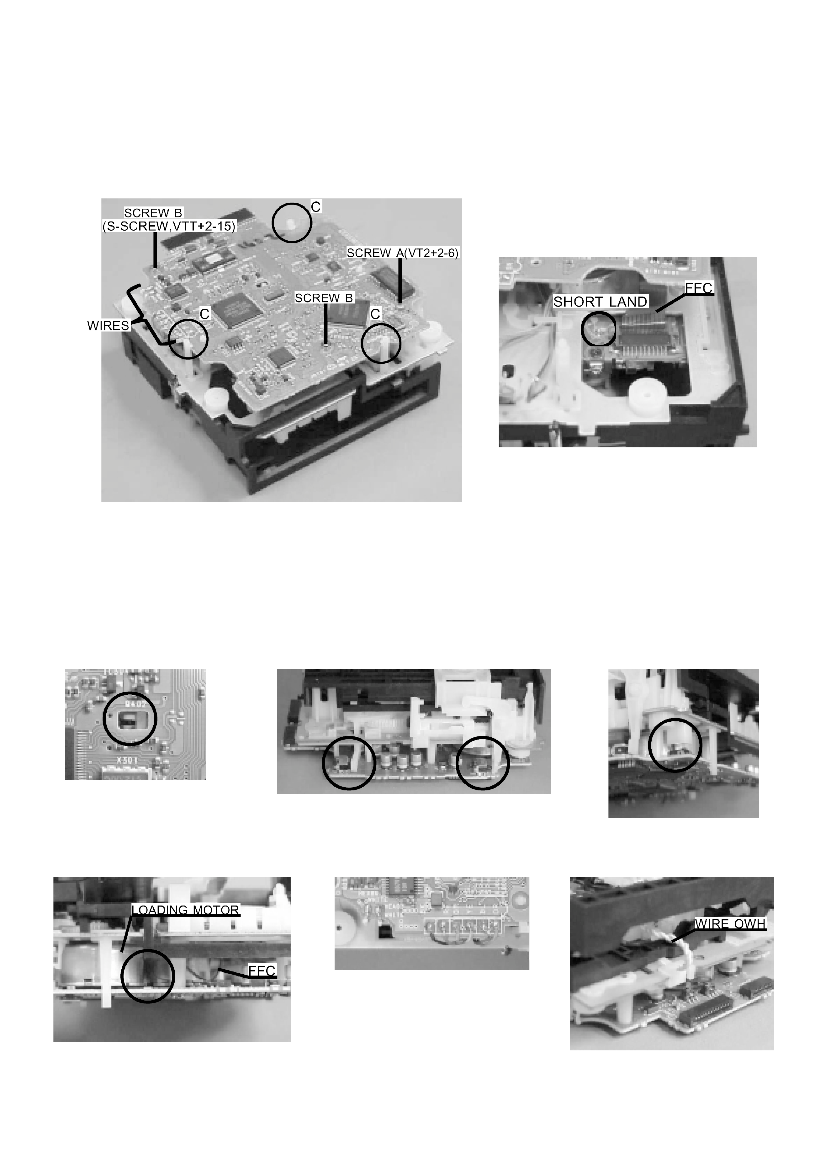
Fig.3-1
Fig.3-2
Fig.3-3 a
Fig.3-3 b
Fig.3-3 c
Fig.3-5
Fig.3-4
Fig.3-6
DISASSEMBLY INSTRUCTIONS-2/6
3. MD C.B
1)
Remove the eight WIRES from the mechanism chassis by a soldering iron.
2)
Remove the two screws, the SCREW A (VT2+2-6) and the SCREW B (S-SCREW, VTT2-15).
3)
Disengage the detent C in the three locations and lift up the MD C. B.
4)
Short-circuit the SHORT LAND of the pick-up. (Fig. 3-2)
5)
Disconnect the FFC of the pick-up and remove the MD C. B. (Fig. 3-2)
Notes for assembling
1)
Remove the short-circuit of the pick-up by unsoldering.
2)
Ensure that the four switches are located correctly. (Fig. 3-3 a, Fig. 3-3 b, Fig. 3-3 c)
3)
Ensure that the FFC of the pick-up is not pinched between the LOADING MOTOR and the PWB. (Fig. 3-4)
4)
Ensure that the WIRES are connected with the mechanism chassis properly by soldering. (Fig. 3-5)
5)
Ensure that the WIRE has an allowance so that the routing range of the WIRE OWH can be secured. (Fig. 3-6)