DVD CD VCD MECHANISM
AZG-D
S/M Code No. 09-00A-350-6N2
English
SERVICE MANUAL
TYPE
ZAAPA
ZAAPAM
ZABPDM
ZACPD
ZACPDM
ZBAPAM
ZBAPAKM
ZFAPAM
ZCAPD
ZCAPDM
BASIC MECHANISM : DV32F DVD
DA
TA
DVD MECHA
DV32F DVD
SIMPLE-2
Apar t ofcontentsisadequate.
Re-issuing is under r equest.

-2-
TABLE OF CONTENTS
PROTECTION OF EYES FROM LASER BEAM DURING SERVICING ............................................................ 3
Precaution to replace Optical block ..................................................................................................................... 4
How to Adjust the Rotating Phase of the Gear, Main Cam ................................................................................. 5
ELECTRICAL MAIN PARTS LIST ................................................................................................................. 6-11
BLOCK DIAGRAM-1/4 (DVD1/2: DVD_BLOCK) .............................................................................................. 12
BLOCK DIAGRAM-2/4 (DVD2/2: FRONT END) ............................................................................................... 13
BLOCK DIAGRAM-3/4 (AC3) ............................................................................................................................ 14
BLOCK DIAGRAM-4/4 (P-SUPPLY) ................................................................................................................. 15
WIRING-1/5 (DVD: COMPONENT SIDE) ......................................................................................................... 16
DVD C.B MOUNT LIST-1/2 (COMPONENT SIDE) .......................................................................................... 17
WIRING-2/5 (DVD: CONDUCTOR SIDE) ......................................................................................................... 18
DVD C.B MOUNT LIST-2/2 (CONDUCTOR SIDE) .......................................................................................... 19
SCHEMATIC DIAGRAM-1/11 (DVD: RF AMP) ................................................................................................ 20
SCHEMATIC DIAGRAM-2/11 (DVD: DSP) ....................................................................................................... 21
SCHEMATIC DIAGRAM-3/11 (DVD: AV DECODER) ...................................................................................... 22
SCHEMATIC DIAGRAM-4/11 (DVD: 5.1CH DECODER) ................................................................................. 23
SCHEMATIC DIAGRAM-5/11 (DVD: VIDEO) ................................................................................................... 24
SCHEMATIC DIAGRAM-6/11 (DVD: POWER/DRIVER) .................................................................................. 25
SCHEMATIC DIAGRAM-7/11 (DVD: µ-COM) .................................................................................................. 26
SCHEMATIC DIAGRAM-8/11 (DVD: SYSCON/TRAY DRIVER) ...................................................................... 27
WIRING-3/5 (AC3) ............................................................................................................................................ 28
SCHEMATIC DIAGRAM-9/11 (AC3) ................................................................................................................. 29
WIRING-4/5 (P-SUPPLY) ................................................................................................................................. 30
SCHEMATIC DIAGRAM-10/11 (P-SUPPLY) .................................................................................................... 31
WIRING-5/5 (D-SENS) ...................................................................................................................................... 32
SCHEMATIC DIAGRAM-11/11 (D-SENS) ........................................................................................................ 33
TRANSISTOR ILLUSTRATION-1/1 .................................................................................................................. 34
WAVE FORM ............................................................................................................................................... 35-37
IC BLOCK DIAGRAM ................................................................................................................................... 38-40
IC DESCRIPTION ........................................................................................................................................ 41-58
MECHANICAL EXPLODED VIEW-1/1 .............................................................................................................. 59
MECHANICAL PARTS LIST-1/1 ................................................................................................................. 60, 61
-3-
PROTECTION OF EYES FROM LASER BEAM DURING SERVICING
VAROITUS!
Laiteen Käyttäminen muulla kuin tässä käyttöohjeessa mainit-
ulla tavalla saattaa altistaa käyt-täjän turvallisuusluokan 1 ylit-
tävälle näkymättömälle lasersäteilylle.
VARNING!
Om apparaten används på annat sätt än vad som specificeras i
denna bruksanvising, kan användaren utsättas för osynling
laserstrålning, som överskrider gränsen för laserklass 1.
Caution: Invisible laser radiation when
open and interlocks defeated avoid expo-
sure to beam.
Advarsel:Usynling laserståling ved åbning,
når sikkerhedsafbrydere er ude af funktion.
Undgå udsættelse for stråling.
CAUTION
Use of controls or adjustments or performance of procedures
other than those specified herein may result in hazardous
radiation exposure.
ATTENTION
L'utilisation de commandes, réglages ou procédures autres que
ceux spécifiés peut entraîner une dangereuse exposition aux
radiations.
ADVARSEL!
Usynlig laserståling ved åbning, når sikkerhedsafbrydereer ude
af funktion. Undgå udsættelse for stråling.
This Compact Disc player is classified as a CLASS 1 LASER
product.
The CLASS 1 LASER PRODUCT label is located on the rear
exterior.
This set employs laser. Therefore, be sure to follow carefully the
instructions below when servicing.
WARNING!
WHEN SERVICING, DO NOT APPROACH THE LASER EXIT
WITH THE EYE TOO CLOSELY. IN CASE IT IS NECESSARY TO
CONFIRM LASER BEAM EMISSION. BE SURE TO OBSERVE
FROM A DISTANCE OF MORE THAN 30cm FROM THE
SURFACE OF THE OBJECTIVE LENS ON THE OPTICAL
PICK-UP BLOCK.
CLASS 1
KLASSE 1
LUOKAN 1
KLASS 1
LASER PRODUCT
LASER PRODUKT
LASER LAITE
LASER APPARAT
-4-
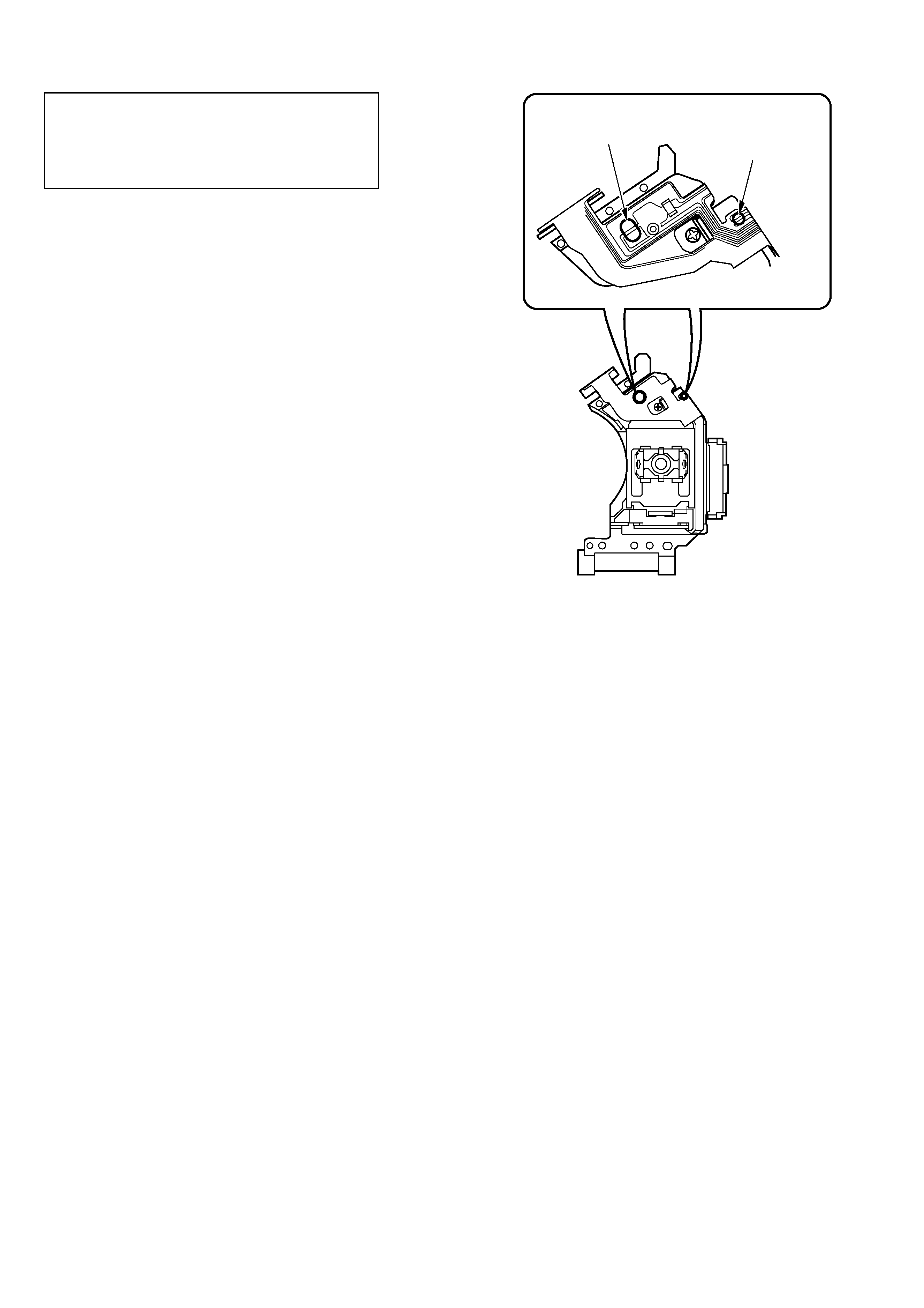
Precaution to replace Optical block
(SF-HD3AV/HD3AVC)
1) After the connection, remove solder shown in
the right figure.
Body or clothes electrostatic potential could ruin
laser diode in the optical block. Be sure ground
body and workbench, and use care the clothes
do not touch the diode.
Solder short land for
DVD laser diode
Solder short land for
CD laser diode
-5-
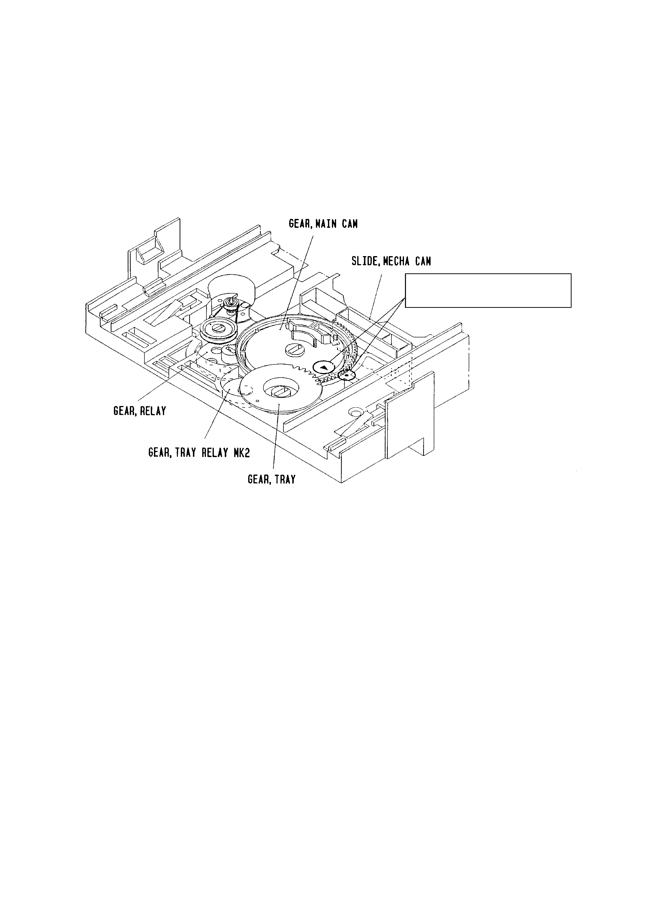
How to Adjust the Rotating Phase of the Gear, Main Cam
Align the arrow
2 mark with the black
round · mark.
1) Push down the hooking catch of the CHAS. MECH, and remove
the TRAY.
2) Align the arrow mark of the Gear, Main Cam with the black round
mark of the CHAS, MECHA as shown below.
3) Confirm that the Slide, Mech Cam is located in the right position,
then insert the TRAY gently.
Caution: If the rotating phase of the Gear, Main Cam is
incorrectly adjusted, the chucking operation and tray
movement will have malfunction.