SERVICE MANUAL
DA
TA
AV SURROUND RECEIVER
AV-NW30
S/M Code No. 09-028-358-2N2
EZ(B,S),K(S)
SIMPLE-2
A part of contents is adequate.
Re-issuing is under request.

-2-
SPECIFICATIONS ................................................................................................................................................................ 3
ACCESSORIES PARTS LIST .............................................................................................................................................. 4
SERVICE POSITION ........................................................................................................................................................... 5
ELECTRICAL PARTS LIST .......................................................................................................................................... 6 29
TRANSISTOR ILLUSTRATION .......................................................................................................................................... 30
SCHEMATIC DIAGRAM-1/9 (MAIN-1/4) ............................................................................................................................. 31
SCHEMATIC DIAGRAM-2/9 (MAIN-2/4) ............................................................................................................................. 32
SCHEMATIC DIAGRAM-3/9 (MAIN-3/4) ............................................................................................................................. 33
SCHEMATIC DIAGRAM-4/9 (MAIN-4/4)(EZ) ....................................................................................................................... 34
SCHEMATIC DIAGRAM-4/9 (MAIN-4/4)(K) ......................................................................................................................... 35
WIRING-1/6(MAIN)(EZ) ..................................................................................................................................................... 36
WIRING-1/6(MAIN)(K) ....................................................................................................................................................... 37
SCHEMATICDIAGRAM-5/9(FRONT)(EZ) .......................................................................................................................... 38
SCHEMATIC DIAGRAM-5/9 (FRONT)(K) ............................................................................................................................ 39
WIRING -2/6 (FRONT)(EZ) ................................................................................................................................................. 40
WIRING -2/6 (FRONT)(K) ................................................................................................................................................... 41
SCHEMATIC DIAGRAM-6/9 (DSP) ..................................................................................................................................... 42
WIRING-3/6 (DSP-1/2) ....................................................................................................................................................... 43
WIRING-3/6 (DSP-2/2) ....................................................................................................................................................... 44
SCHEMATIC DIAGRAM-7/9 (TUNER) ................................................................................................................................45
WIRING-4/6(TUNER) ......................................................................................................................................................... 46
SCHEMATIC DIAGRAM-8/9 (SUB-PT) ............................................................................................................................... 47
WIRING-5/6 (SUB-PT) ........................................................................................................................................................ 48
SCHEMATIC DIAGRAM-9/9 (KEY/LED,HP/VIDEO,AC1,AC2) ............................................................................................ 49
WIRING-6/6 (KEY/LED,HP/VIDEO,AC1,AC2) .................................................................................................................... 50
LCD DIAGRAM .................................................................................................................................................................. 51
ELECTRICALADJUSTMENT ..................................................................................................................................... 52 57
IC BLOCK DIAGRAM ......................................................................................................................................................... 58
ICDESCRIPTION ....................................................................................................................................................... 59 65
MECHANICAL EXPLODED VIEW ..................................................................................................................................... 66
MECHANICAL PARTS LIST .............................................................................................................................................. 67
COLOR NAME TABLE ....................................................................................................................................................... 68
OTHER PARTS LIST ......................................................................................................................................................... 69
TABLE OF CONTENTS - 1/1
-3-
SPECIFICATIONS - 1/1
· Design and specifications are subject to change without
notice
.
:
<EZMODEL>
:
<EZMODEL>
:
<EZMODEL>

!
= ! SAFTY PARTS
C
= Components marked
All components used on this model at the production line are shown in this service manual.
However, please note that not all components will be available as spare parts for after-sales service.
Components marked S and O are designated as spare parts for service and will be stocked at the spare parts centers.
Components marked X and R are not designated as spare parts for after sales service, and will not be stocked at the spare parts centers.
UNIT-NAME
! C REF-NO PARTS-NO
PARTS-NAME
SUFFIX&MODEL
-4-
ACCESSORIES PARTS LIST - 1/1
AV-NW30
AV-NW30
AV-NW30
EZSC
EZBC
KSC
O AS1001
87-006-226-010 ANT,LOOP AM
X a
b
c
O AS1002
87-A92-346-010 ANT,WIRE FM(FASTEN)
X a
b
c
O AS1003
8C-AR6-711-010 RC UNIT,RC-CAR02
a
b
c
! O AS1004
87-099-811-010 PLUG,ADPTR CONV(K)
X .
.
c
O AS1005
8C-AR6-905-010 IB,K(E)S AV-NW30
.
.
c
O AS1006
8C-AR6-906-010 IB,EZ(9L)S AV-NW30
a
b
.
-5-
SERVICE POSITION - 1/1
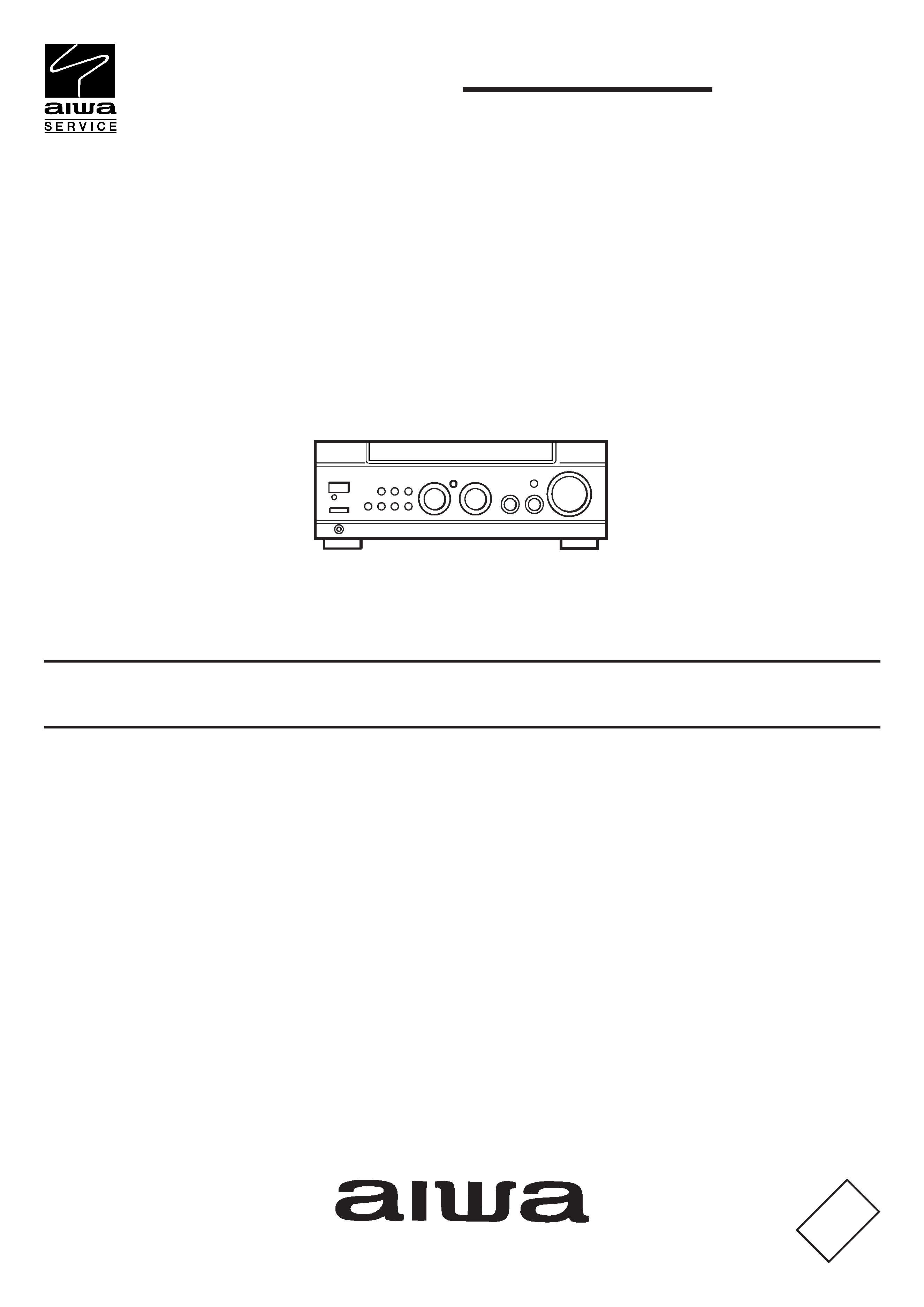
1. Service Position of the MAIN Board
(1) Remove the four screws (A) securing the heat sink and the two screws (B)
Securing the MAIN board.
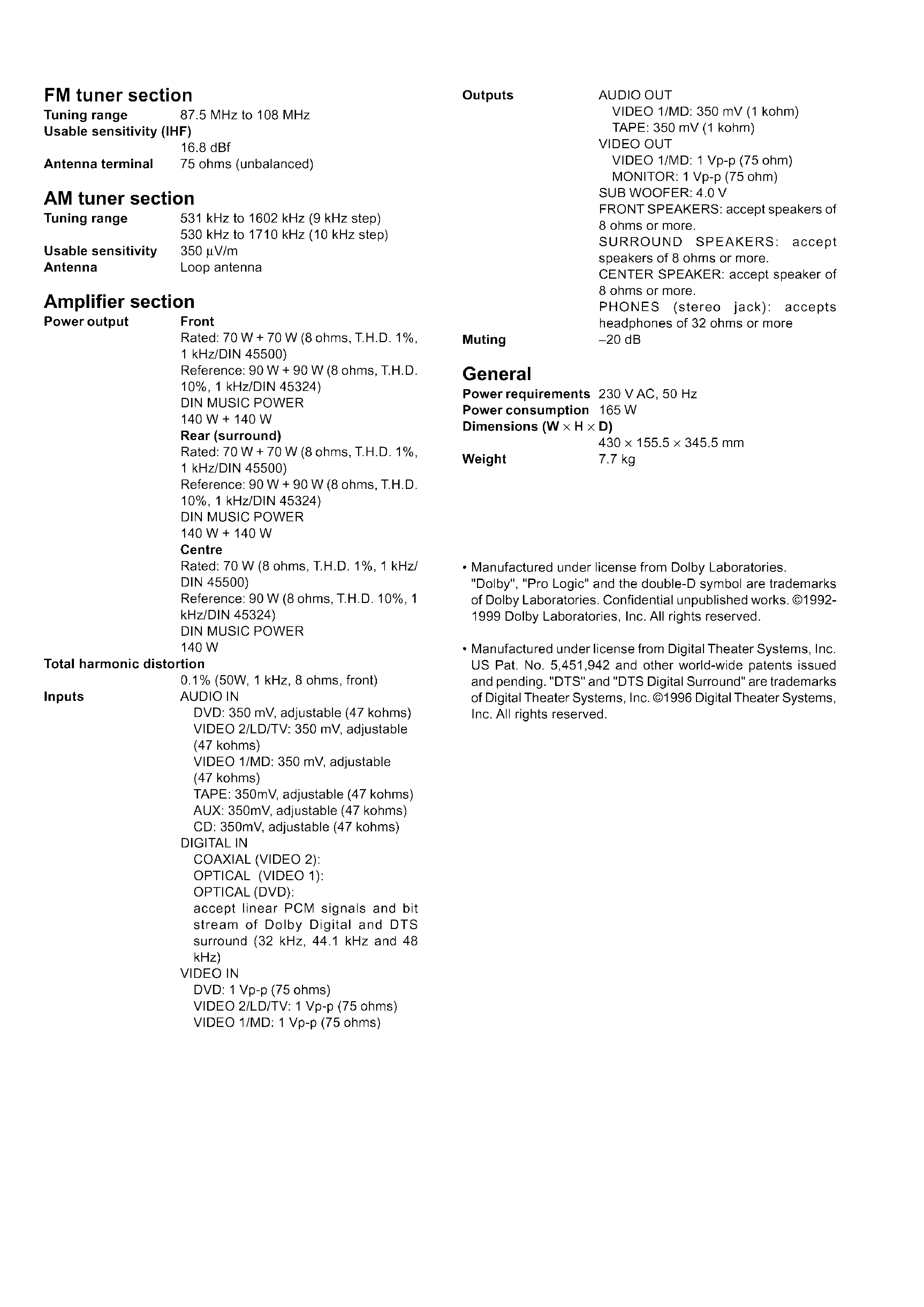
(2) Remove the five screws (C).
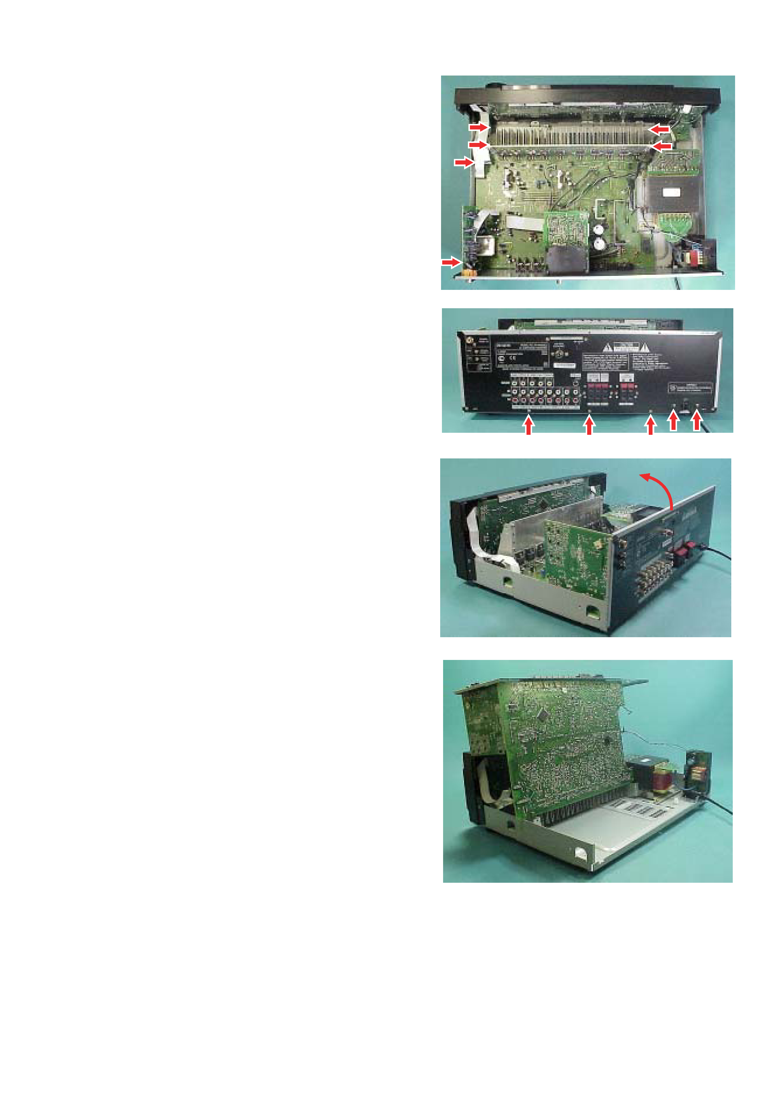
(3) Lift up the rear panel together with the MAIN board.
(4) Service position of the MAIN board.
(A)
(A)
(B)
(B)
(C)
(C)
(C) (C) (C)