STEREO RECEIVER
RECEPTOR ESTEREO
AMPLI-TUNER STEREO
U
OPERATING INSTRUCTIONS
MANUAL DE INSTRUCCIONES
MODE D'EMPLOI
En (English)
8A-AR2-913-01
000215ACK-Y-M
F (Français)
AV-D77
For assistance and information
call toll free 1-800-BUY-AIWA
(United States and Puerto Rico)
E (Español)
1 ENGLISH
ENGLISH
Owner's record
For your convenience, record the model number and serial
number (you will find them on the rear of your unit) in the space
provided below. Please refer to them when you contact your Aiwa
dealer in case of difficulty.
Model No.
Serial No. (Lot No.)
AV-D77
PRECAUTIONS
Read the Operating Instructions carefully and completely before
operating the unit. Be sure to keep the Operating Instructions
for future reference. All warnings and cautions in the Operating
Instructions and on the unit should be strictly followed, as well
as the safety suggestions below.
Installation
1 Water and moisture -- Do not use this unit near water, such
as near a bathtub, washbowl, swimming pool, or the like.
2 Heat -- Do not use this unit near heat sources, including
heating vents, stoves, or other appliances that generate heat.
It also should not be placed in temperatures less than 5°C
(41°F) or higher than 35°C (95°F).
3 Mounting surface -- Place the unit on a flat, even surface.
4 Ventilation -- The unit should be situated with adequate
space around it so that proper heat ventilation is assured.
Allow 10 cm (4 in.) clearance from the rear and the top of the
unit, and 5 cm (2 in.) from each side.
- Do not place the unit on a bed, rug, or similar surface that
may block the ventilation openings.
- Do not install the unit in a bookcase, cabinet, or airtight
rack where ventilation may be impeded.
5 Objects and liquid entry -- Take care that objects or liquids
do not get inside the unit through the ventilation openings.
6 Carts and stands -- When placed or
mounted on a stand or cart, the unit
should be moved with care.
Quick stops, excessive force, and
uneven surfaces may cause the unit or
cart to overturn or fall.
7 Wall or ceiling mounting -- The unit should not be mounted
on a wall or ceiling, unless specified in the Operating
Instructions.
Electric Power
1 Power sources -- Connect this unit only to power sources
specified in the Operating Instructions, and as marked on the
unit.
2 Polarization -- As a safety feature, some units are equipped
with polarized AC power plugs which can only be inserted
one way into a power outlet. If it is difficult or impossible to
insert the AC power plug into an outlet, turn the plug over
and try again. If it is not still inserted easily into the outlet,
please call a qualified service technician to service or replace
the outlet. To avoid defeating the safety feature of the polarized
plug, do not force it into a power outlet.
3 AC power cord
- When disconnecting the AC power cord, pull it out by the
AC power plug. Do not pull the cord itself.
- Never handle the AC power plug with wet hands, as this
could result in fire or shock.
- Power cords should be firmly secured to avoid being severely
bent, pinched, or walked upon. Pay particular attention to
the cord from the unit to the power socket.
- Avoid overloading AC outlets and extension cords beyond
their capacity, as this could result in fire or shock.
4 Extension cord -- To help prevent electric shock, do not
use a polarized AC power plug with an extension cord,
receptacle, or other outlet unless the polarized plug can be
completely inserted to prevent exposure of the blades of the
plug.
5 When not in use -- Unplug the AC power cord from the AC
power outlet if the unit will not be used for several months or
more. When the cord is plugged in, a small amount of current
continues to flow to the unit, even when the power is turned
off.
WARNING
TO REDUCE THE RISK OF FIRE OR
ELECTRIC SHOCK, DO NOT EXPOSE THIS
APPLIANCE TO RAIN OR MOISTURE.
RISK OF ELECTRIC SHOCK
DO NOT OPEN
"CAUTION: TO REDUCE THE RISK OF
ELECTRIC SHOCK,
DO NOT REMOVE COVER (OR BACK).
NO USER-SERVICEABLE PARTS INSIDE.
REFER SERVICING TO QUALIFIED
SERVICE PERSONNEL."
Explanation of Graphical Symbols:
The lightning flash with arrowhead symbol,
within an equilateral triangle, is intended to
alert the user to the presence of uninsulated
"dangerous voltage" within the product's
enclosure that may be of sufficient
magnitude to constitute a risk of electric
shock to persons.
The exclamation point within an equilateral
triangle is intended to alert the user to the
presence of important operating and
maintenance (servicing) instructions in the
literature accompanying the appliance.
En
En
En
En
En
ENGLISH
2
EEEEE (Españo
(Españo
(Españo
(Españo
(Españo
FFFFF (França
(França
(França
(França
(França
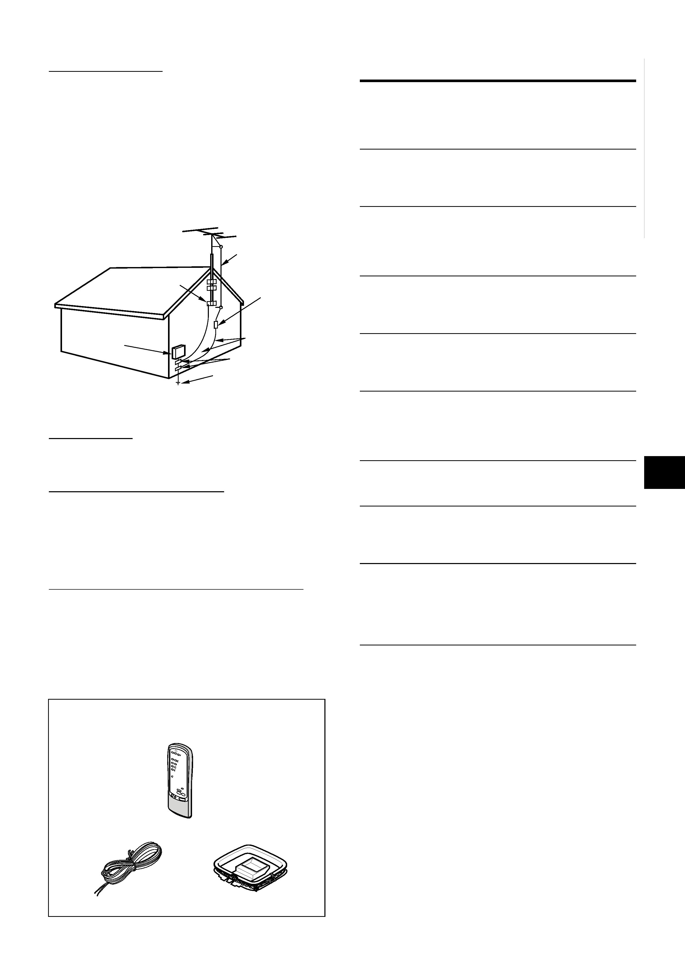
Remote control
FM antenna
AM antenna
Operating Instructions, etc.
Outdoor Antenna
1 Power lines -- When connecting an outdoor antenna, make
sure it is located away from power lines.
2 Outdoor antenna grounding -- Be sure the antenna system
is properly grounded to provide protection against unexpected
voltage surges or static electricity build-up. Article 810 of the
National Electrical Code, ANSI/NFPA70, provides information
on proper grounding of the mast, supporting structure, and
the lead-in wire to the antenna discharge unit, as well as the
size of the grounding unit, connection to grounding terminals,
and requirements for grounding terminals themselves.
Maintenance
Clean the unit only as recommended in the Operating
Instructions.
Damage Requiring Service
Have the unit serviced by a qualified service technician if:
- The AC power cord or plug has been damaged
- Foreign objects or liquid have gotten inside the unit
- The unit has been exposed to rain or water
- The unit does not seem to operate normally
- The unit exhibits a marked change in performance
- The unit has been dropped, or the cabinet has been damaged
DO NOT ATTEMPT TO SERVICE THE UNIT YOURSELF.
TABLE OF CONTENTS
PRECAUTIONS ................................................................... 1
PREPARATIONS
CONNECTIONS .................................................................. 3
BEFORE OPERATION ........................................................ 7
SOUND
CUSTOM AUDIO ADJUSTMENT ....................................... 8
ELECTRONIC GRAPHIC EQUALIZER .............................. 9
DSP SURROUND .............................................................. 10
BASIC OPERATIONS
SELECTION OF AUDIO/VIDEO SOURCE ....................... 11
RECORDING AN AUDIO SOURCE ................................. 12
RADIO RECEPTION
MANUAL TUNING ............................................................. 13
PRESETTING STATIONS ................................................. 14
DOLBY SURROUND AND DTS SURROUND
SELECTING DOLBY SURROUND ................................... 15
ADJUSTING DOLBY DIGITAL SURROUND SOUND ..... 18
SELECTING DTS SURROUND ........................................ 19
REMOTE CONTROL
OPERATING TV, CABLE TV, VCR AND CD PLAYER ...... 20
TIMER
SETTING THE CLOCK ...................................................... 21
SETTING THE SLEEP TIMER .......................................... 21
GENERAL
SPECIFICATIONS ............................................................. 22
CARE AND MAINTENANCE ............................................ 23
TROUBLESHOOTING GUIDE .......................................... 23
PARTS INDEX ................................................................... 23
APPENDIX
ID CODES FOR TV .......................................................... A-1
ID CODES FOR CABLE TV ............................................ A-3
ID CODES FOR VCR ...................................................... A-4
ID CODES FOR CD PLAYER ......................................... A-5
ID CODES FOR DSS SATELLITE .................................. A-6
Check your accessories
ANTENNA LEAD IN WIRE
ANTENNA DISCHARGE
UNIT
(NEC SECTION 810-20)
GROUNDING
CONDUCTORS
(NEC SECTION 810-21)
GROUND CLAMPS
POWER SERVICE GROUNDING
ELECTRODE SYSTEM
(NEC ART 250 PART H)
NEC-NATIONAL ELECTRICAL CODE
ELECTRIC
SERVICE
EQUIPMENT
GROUND CLAMP
Antenna Grounding According to the National Electrical Code
3 ENGLISH
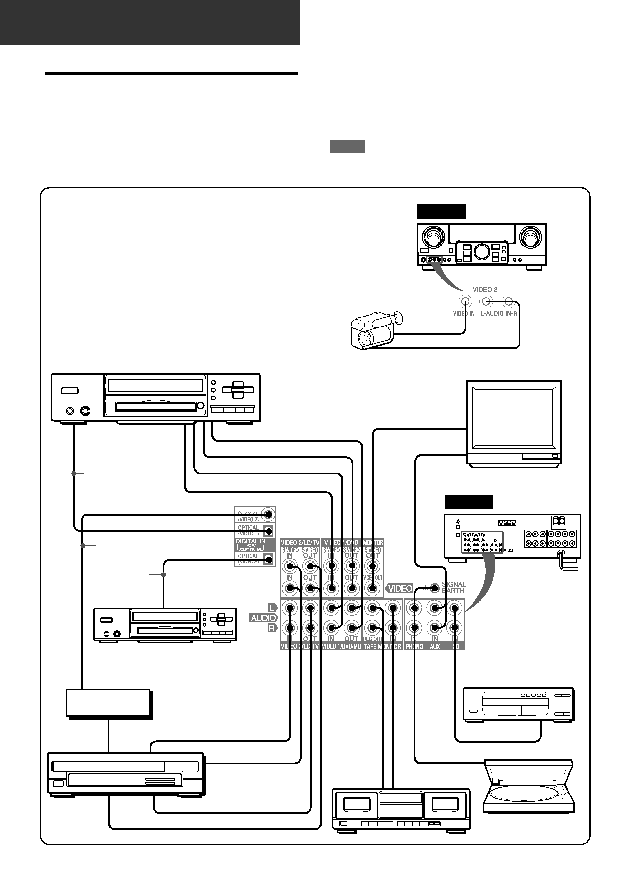
CONNECTING EQUIPMENT
Jacks and plugs of the connecting cord are color-coded as
follows:
Red jacks and plugs : For the right channel of audio signals
White jacks and plugs: For the left channel of audio signals
Yellow or black jacks and plugs: For video or S-video signals
NOTE
Insert the plugs fully into the jacks. Loose connections may
produce a humming sound or other noise interference.
CONNECTIONS
Before connecting the AC cord
The rated voltage of your unit shown on the rear panel is 120 V
AC. Check that the rated voltage matches your local voltage.
IMPORTANT
Connect the speakers, antennas, and all other external
equipment first. Then connect the AC cord at the end.
PREPARATIONS
*1 Be sure to connect the VIDEO (S VIDEO) OUT terminal of a
DVD player directly to a TV set, not through this unit. Otherwise,
the picture noise may appear when playing copy protected
DVDs.
*2 Input sound through the DIGITAL IN terminals cannot be
recorded. When recording the sound from the DVD, CD, MD
or LD player, connect the analog AUDIO OUT terminals of the
player to the corresponding AUDIO IN terminals of the receiver.
*3 When connecting a monaural video, use a stereo-mono
connecting cord (not supplied).
*4 When connecting an LD player equipped with the AC-3 RF
OUT terminal, use an RF demodulator unit. Also connect the
analog AUDIO OUT terminals of the LD player to the receiver
to play all the sources. For further information, refer to the
instructions of the LD player.
*1
TV
Video 2* or
LD* /Cable TV
DVD or Video 1* /MD player
to VIDEO(S VIDEO)IN(Video 1)
to AUDIO IN(Video 1/MD)
to VIDEO(S VIDEO) IN
to AUDIO OUTPUT
to AUDIO OUT
to COAXIAL
DIGITAL OUT
to OPTICAL
DIGITAL OUT
Coaxial connecting
cord
Optical
connecting
cord
to OPTICAL
DIGITAL OUT
(DVD)
to AUDIO IN (Video 2)
to VIDEO(S VIDEO)OUT
to VIDEO(S VIDEO)IN (Video 2)
3
4
RF demodulator*
DVD or MD Player
4
3
Optical
connecting
cord
CD player
Turntable
Tape deck
to OUTPUT
to LINE OUT
to LINE IN
to VIDEO(S VIDEO)OUT(Video 1)
to AUDIO OUT
1
*2
*2
REAR
FRONT
Camcorder
to VIDEO OUT
to AUDIO OUT
o
o
o
o
o
o
o
o
o
o
o
o
o
o
o
o
o
En
En
En
En
En
ENGLISH
4
EEEEE (Españo
(Españo
(Españo
(Españo
(Españo
FFFFF (França
(França
(França
(França
(França
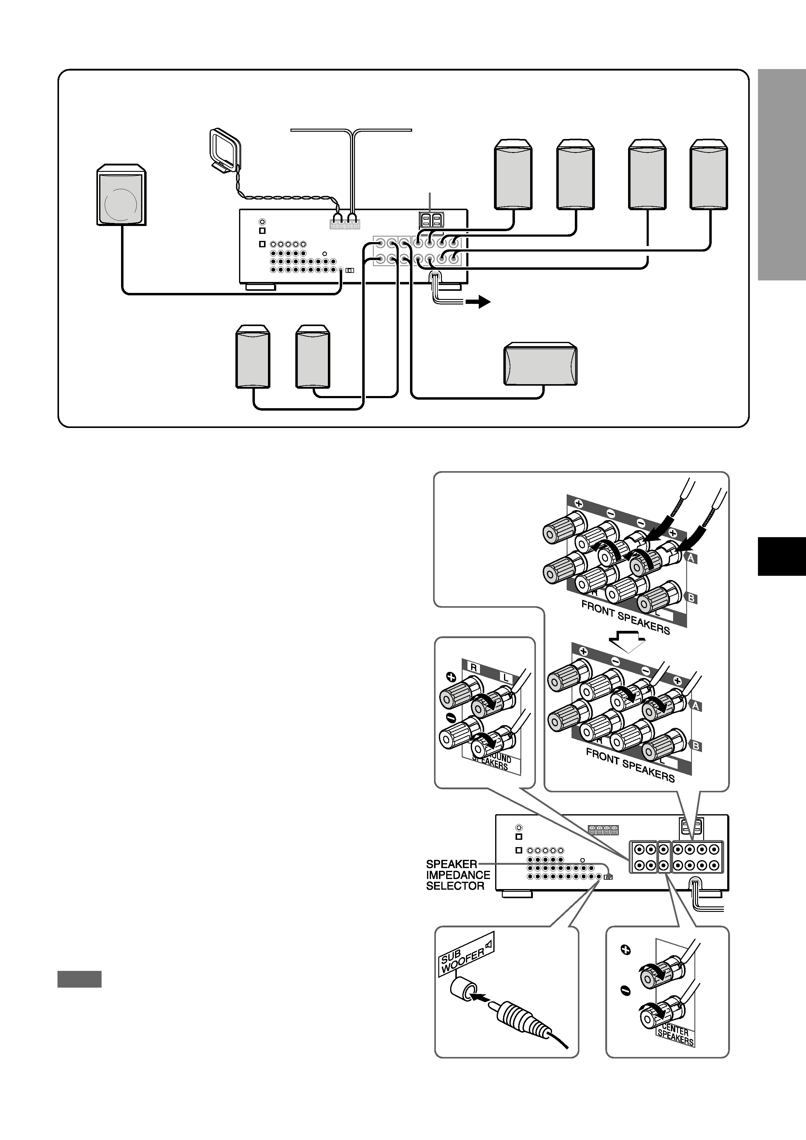
CONNECTING SPEAKERS1
Speaker terminals
Connect front speakers (system A and/or B), a center speaker,
surround speakers and sub woofer to the corresponding speaker
terminals on the unit:
- the front speaker cords to the FRONT SPEAKERS terminals
- the center speaker cord to the CENTER SPEAKER terminals
- the surround speaker cords to the SURROUND SPEAKERS
terminals.
- for more powerful bass, the sub woofer (with a built-in amplifier)
cord to the SUB WOOFER
3 jack
When connecting the sub woofer, be sure to select the
"SUBW ON" (sub woofer on) mode (see page 5).
Speaker impedance
· Front and center speakers
Use the same impedance for both the front and center speakers.
The SPEAKER IMPEDANCE SELECTOR on the rear should be
set to the position that matches the impedance value of the front
and center speakers.
When using 4 ohm speakers, set the selector to IMP:4
. When
using 8 ohm speakers, set the selector to IMP:8
. Please unplug
the AC cord before setting the selector.
· Surround speakers and sub woofer
The SPEAKER IMPEDANCE SELECTOR has no effect on the
SURROUND SPEAKERS terminals and the SUB WOOFER
3
jack. For the surround speakers and sub woofer, use speakers
of 8 ohms or more.
Connecting + to +, to terminals
To get the proper sound effect, the speaker terminals on the unit
and the speaker should be connected with proper polarity; the +
terminal on the unit should be connected to the + terminal on
the speaker (and to ).
NOTE
· Be sure to connect the speaker cords correctly as shown in
the illustration on the right column. Improper connections can
cause short circuits in the SPEAKER(S) terminals.
· Do not leave objects generating magnetism near the speakers.
PREP
ARA
TIONS
Sub woofer
Center speaker
1, 2 and 3 in the illustration correspond to the following details.
Surround speakers
Front speakers
Wind the tip of the
cord
around
the
terminal.Then tighten
the terminal. Check
that the cord is
connected securely.
1Speaker system B
Right
Left
1Speaker system A
Right
Left
1Surround speakers
Right
Left
1Center speaker
1Sub woofer
3FM antenna
2AC outlets
3AM antenna