
- 1 -
SERVICE MANUAL
Plasma Monitor
42DPC85
FILE NO. 020-200521
Published in Japan, Sep. 2005 (YC)
TOSHIBA CORPORATION 2005
DOCUMENT CREATED IN JAPAN, Sept., 2005

- 2 -
TABLE OF CONTENTS
SERVICE SAFETY PRECAUTIONS .................................................................................................................................... 3
SERVICE MODE .................................................................................................................................................................. 5
LAYOUT OF MAJOR BOARDS .......................................................................................................................................... 10
MECHANICAL DISASSEMBLY .......................................................................................................................................... 11
EXPLODED VIEW .............................................................................................................................................................. 13
PACKING DISASSEMBLY ................................................................................................................................................. 15
CHASSIS AND CABINET REPLACEMENT PARTS LIST ................................................................................................. 16
PC BOARDS TOP & BOTTOM VIEW ................................................................................................................................ 19
CIRCUIT BLOCK DIAGRAM .............................................................................................................................................. 33
APPENDIX:
SCHEMATIC DIAGRAM
- 3 -
GENERAL
ADJUSTMENTS
SPECIFIC
INFORMATIONS
SERVICE SAFETY PRECAUTIONS
· The caution items shown here describe major safety issues and should always be observed.
· The meanings of the various indications are as follows.
WARNING
CAUTION
Indicates a hypothetical situation in which service personnel and nearby third parties, or even
end users due to a product defect after the service operation is completed, could possibly be in
danger of injury or even death in the event of operational error.
Indicates a hypothetical situation in which service personnel and nearby third parties, or even
end users after the service operation is completed, could possibly be in danger of injury, or
where there could be physical damage in the event of operational error.
* Physical damage means major damage to a home, furnishings and other possessions.
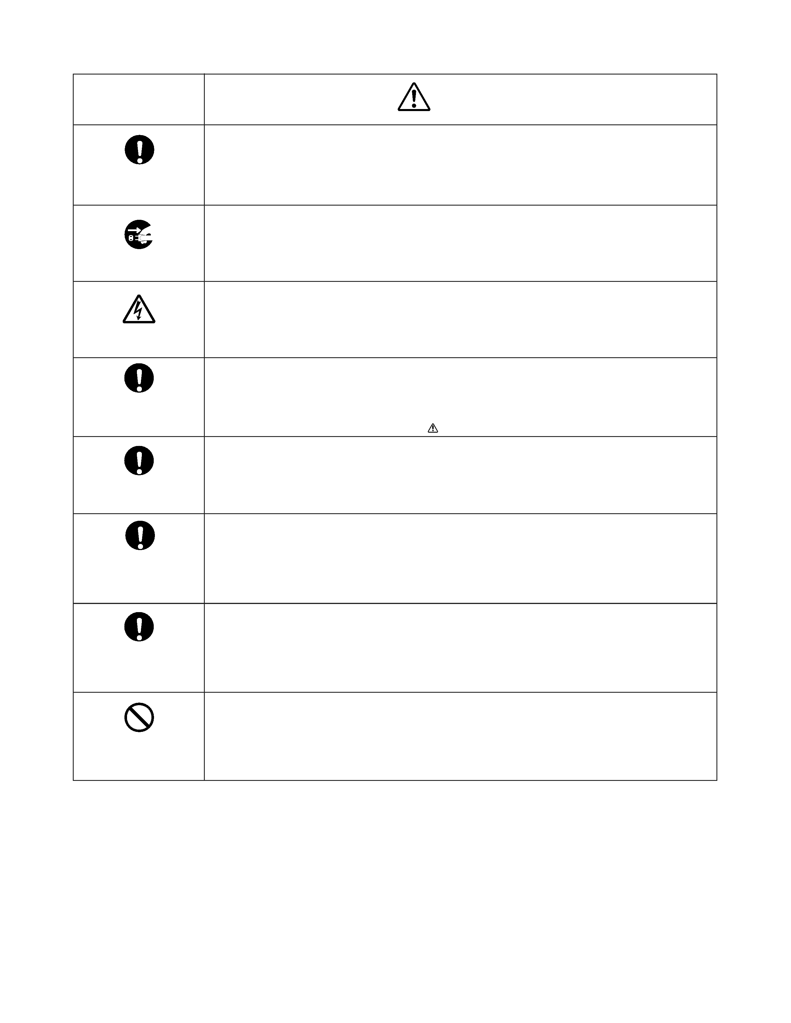
Examples of marks
SHOCK HAZARD
PROHIBIT DISASSEM-
BLING
UNPULUG
The
" indicates caution (including danger and warning).
The actual meaning of this caution is indicated inside the
" or nearby illustrations or text.
The example shown to the left indicates the danger of "electrical shock".
The
indicates a forbidden action.
The actual meaning of this caution is indicated inside the
or nearby illustrations or text.
The example shown to the left indicates that disassembly is forbidden.
The
- indicates a forced action (an action that must be performed).
The actual meaning of this forced action is indicated by
- or nearby illustrations or text.
The example shown to the left indicates that the power plug must be disconnected.
- 4 -
WARNING
KEEP CHILDREN
AWAY
UNPULUG
SHOCK HAZARD
USE SPECIFIED
PARTS
CAUTION FOR
WIRING
CAUTION FOR
ASSEMBLING /
WIRING
CHECK INSULATION
RESISTANCE
PROHIBIT
REMODELING
· Always advise users to keep children away.
There is danger of injury to children from tools, disassembled products, etc.
· Always disconnect the power plug before starting work whenever power is not required.
Failure to disconnect the power plug before starting work can result in electrical shock.
· Depending on the model, use an insulation transformer or wear gloves when servicing with the
power on, and disconnect the power plug to avoid electrical shock when replacing parts.
In some cases, alternating current is also impressed in the chassis, so electrical shock is pos-
sible if the chassis is contacted with the power on.
· Always use the replacement parts specified for the particular model when making repairs.
The parts used in products have the necessary safety characteristics such as inflammability,
voltage resistance, etc.; therefore, use only replacement parts that have these same character-
istics.
Use only the specified parts when the
mark is included in a circuit diagram or parts list.
· Parts mounting and routing of the wiring should be the same as that used originally.
For safety purposes, insulating materials such as tubing or tape is sometimes used and printed
circuit boards are sometimes mounted floating.
Also make sure that wiring is routed and clamped to avoid parts that generate heat and which
use high voltage. Always follow the original scheme.
· After a repair has been completed, reassemble all disassembled parts, and route and recon-
nect the wiring, in accordance with the original scheme.
Do not allow internal wiring to be pinched by cabinets, panels, etc.
Any error in reassembly or wiring can result in electrical leakage, flame, etc., and may be
hazardous.
· After completing the work, disconnect the power plug from the outlet, remove the antenna, turn
on the power switch. Then, use a 500V insulation resistance meter to check the insulation
resistance of the antenna terminal, other metallic parts and between the prongs of the power
plug to make sure that the insulation resistance is 1M
or more.
The set will require inspection and repair if the insulation resistance is below this value.
· Never remodel the product in any way.
Remodeling can result in improper operation, malfunction, or electrical leakage and flame,
which may be hazardous
- 5 -
CAUTION : Never try to perform initialization unless you have changed the memory IC.
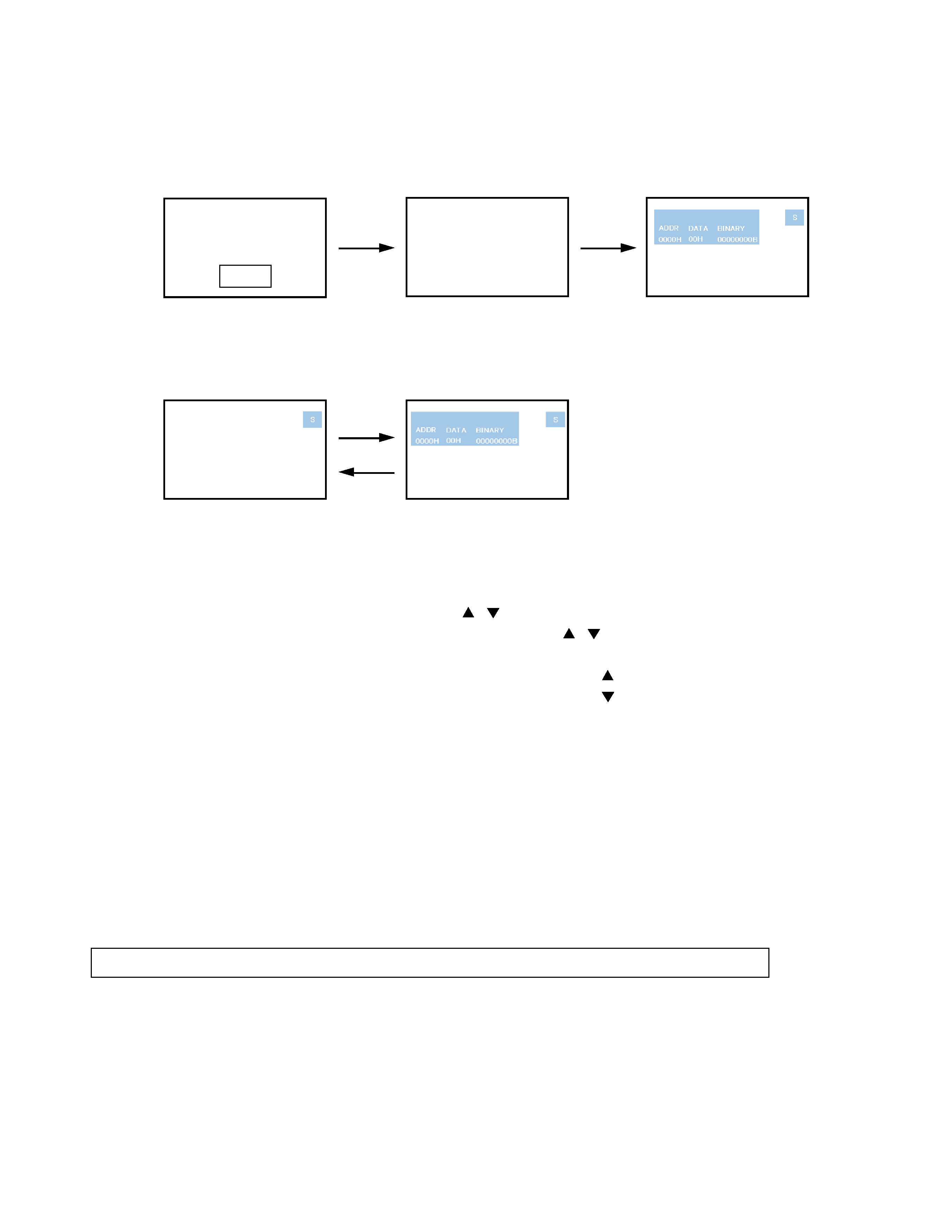
SERVICE MODE
1. ENTERING SERVICE MODE
1)
Press MUTE button twice on
2)
Press MUTE button again and
3)
While pressing the MUTE button,
Remote Control.
keep pressing.
press MENU button on TV set.
(Service mode display)
2. DISPLAYING THE ADJUSTMENT MENU
1)
Press MENU button on Remote Control.
Service mode
Adjustment mode
3. KEY FUNCTION IN THE SERVICE MODE
The following key entry during display of adjustment menu provides special functions.
Press
Press
MUTE
Test signal selection :
INPUT button (on Remote)
Selection of the adjustment items :
Channel
/
(on TV or Remote)
Change of the data value :
Volume
/
(on TV) or
/
(on Remote)
Adjustment menu mode ON/OFF :
MENU button (on Remote)
Initialization of the memory :
CALL + Channel button on TV (
)
Reset the count of operating protect circuit to "00" : CALL + Channel button on TV (
)
"RCUT" selection :
1 button
"GCUT" selection :
2 button
"BCUT" selection :
3 button
"CNTX" selection :
4 button
"COLC" selection :
5 button
"UVTT" selection :
6 button
Automatic A/D Adjustment(PC, Component) : 7 button
Self diagnostic display ON/OFF :
9 button
-----Color thickness correction
note: Displayed differently as shown below, depending
on the setting of the receiving color system.
COLP (PAL)
COLC (NTSC)
COLS (SECAM)