»
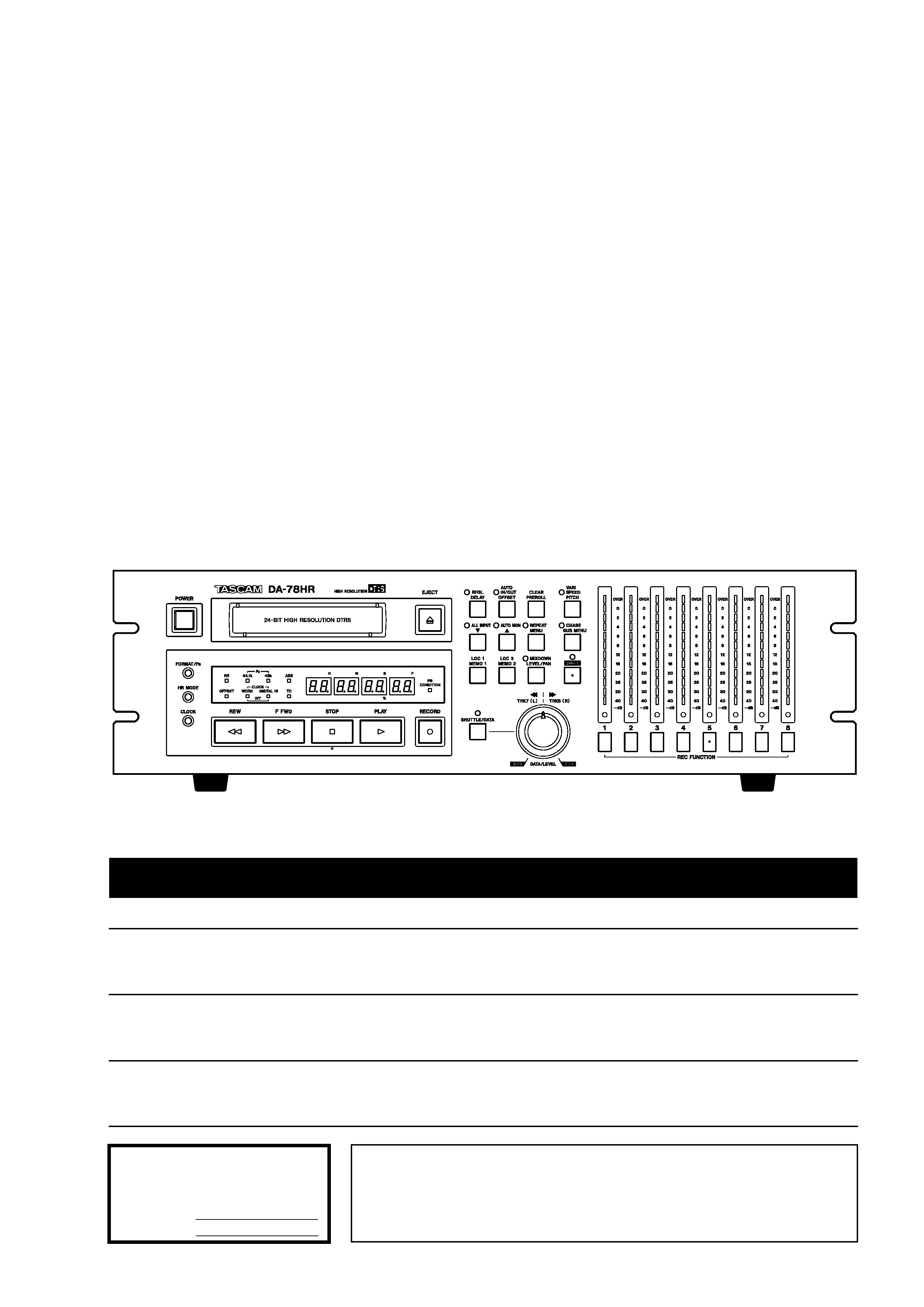
DA-78HR
Digital Multitrack Recorder
OWNER'S MANUAL
CAUTION: TO REDUCE THE RISK OF ELECTRIC SHOCK, DO NOT
REMOVE COVER (OR BACK). NO USER-SERVICEABLE PARTS
INSIDE. REFER SERVICING TO QUALIFIED SERVICE PERSONNEL.
The exclamation point within an equilateral triangle is intended to alert the user to the pres-
ence of important operating and maintenance (servicing) instructions in the literature
accompanying the appliance.
The lightning flash with arrowhead symbol, within an equilateral triangle, is intended to alert
the user to the presence of uninsulated "dangerous voltage" within the product's enclosure
that may be of sufficient magnitude to constitute a risk of electric shock to persons..
This appliance has a serial number
located on the rear panel. Please record
the model number and serial number
and retain them for your records.
Model number
Serial number
Ü
ÿ
Y
WARNING: TO PREVENT FIRE OR SHOCK
HAZARD, DO NOT EXPOSE THIS
APPLIANCE TO RAIN OR MOISTURE.
D00524000A

2 TASCAM DA-78HR
Important Safety Precautions
IMPORTANT (for U.K. Customers)
DO NOT cut off the mains plug from this equipment.
If the plug fitted is not suitable for the power points in your home or
the cable is too short to reach a power point, then obtain an
appropriate safety approved extension lead or consult your dealer.
If nonetheless the mains plug is cut off, remove the
fuse and dispose of the plug immediately, to avoid
a possible shock hazard by inadvertent connection to the mains
supply.
If this product is not provided with a mains plug, or one has to be
fitted, then follow the instructions given below:
IMPORTANT: The wires in this mains lead are coloured in
accordance with the following code:
GREEN-AND-YELLOW
: EARTH
BLUE
: NEUTRAL
BROWN
: LIVE
WARNING: This apparatus must be earthed.
As the colours of the wires in the mains lead of this apparatus may
not correspond with the coloured markings identifying the terminals
in your plug proceed as follows:
The wire which is coloured GREEN-and-YELLOW must be
connected to the terminal in the plug which is marked by the letter
E or by the safety earth symbol
ç or coloured GREEN or GREEN-
and-YELLOW.
The wire which is coloured BLUE must be connected to the terminal
which is marked with the letter N or coloured BLACK.
The wire which is coloured BROWN must be connected to the
terminal which is marked with the letter L or coloured RED.
When replacing the fuse only a correctly rated approved type should
be used and be sure to re-fit the fuse cover.
IF IN DOUBT -- CONSULT A COMPETENT ELECTRICIAN.
TO THE USER
This equipment has been tested and found to
comply with the limits for a Class A digital device,
pursuant to Part 15 of the FCC Rules. These
limits are designed to provide reasonable
protection against harmful interference when the
equipment
is
operated
in
a
commercial
environment. This equipment generates, uses,
and can radiate radio frequency energy and, if
not installed and used in accordance with the
instruction
manual,
may
cause
harmful
interference to radio communications.
Operation of this equipment in a residental area
is likely to cause harmful interference in which
case the user will be required to correct the
interference at his own expense.
CAUTION
Changes or modifications to this equipment not
expressly approved by TEAC CORPORATION
for compliance could void the user's authority to
operate this equipment.
For the consumers in Europe
WARNING
This is a Class A product. In a domestic environment, this
product may cause radio interference in which case the user
may be required to take adequate measures.
Pour les utilisateurs en Europe
AVERTISSEMENT
Il s'agit d'un produit de Classe A. Dans un environnement
domestique, cet appareil peut provoquer des interférences
radio, dans ce cas l'utilisateur peut être amené à prendre
des mesures appropriées.
Für Kunden in Europa
Warnung
Dies is eine Einrichtung, welche die Funk-Entstörung nach
Klasse A besitzt. Diese Einrichtung kann im Wohnbereich
Funkstörungen versursachen ; in diesem Fall kann vom
Betrieber verlang werden, angemessene Maßnahmen
durchzuführen und dafür aufzukommen.
For U.S.A
TASCAM DA-78HR
3
CAUTION:
...Read all of these Instructions.
...Save these Instructions for later use.
...Follow all Warnings and Instructions marked on the audio
equipment.
1) Read Instructions -- All the safety and operating instructions should
be read before the product is operated.
2) Retain Instructions -- The safety and operating instructions should
be retained for future reference.
3) Heed Warnings -- All warnings on the product and in the operating
instructions should be adhered to.
4) Follow Instructions -- All operating and use instructions should be
followed.
5) Cleaning -- Unplug this product from the wall outlet before cleaning.
Do not use liquid cleaners or aerosol cleaners. Use a damp cloth for clean-
ing.
6) Attachments -- Do not use attachments not recommended by the
product manufacturer as they may cause hazards.
7) Water and Moisture -- Do not use this product near water -- for
example, near a bath tub, wash bowl, kitchen sink, or laundry tub; in a wet
basement; or near a swimming pool; and the like.
8) Accessories -- Do not place this product on an unstable cart, stand,
tripod, bracket, or table. The product may fall, causing serious injury to a
child or adult, and serious damage to the product. Use only with a cart,
stand, tripod, bracket, or table recommended by the manufacturer, or sold
with the product. Any mounting of the product should follow the manufac-
turer's instructions, and should use a mounting accessory recommended by
the manufacturer.
9) A product and cart combination should be moved with care. Quick stops,
excessive force, and uneven surfaces may cause the product and cart com-
bination to overturn.
10) Ventilation -- Slots and openings in the cabinet are provided for ven-
tilation and to ensure reliable operation of the product and to protect it
from overheating, and these openings must not be blocked or covered. The
openings should never be blocked by placing the product on a bed, sofa,
rug, or other similar surface. This product should not be placed in a built-in
installation such as a bookcase or rack unless proper ventilation is provided
or the manufacturer's instructions have been adhered to.
11) Power Sources -- This product should be operated only from the
type of power source indicated on the marking label. If you are not sure of
the type of power supply to your home, consult your product dealer or local
power company. For products intended to operate from battery power, or
other sources, refer to the operating instructions.
12) Grounding or Polarization -- This product may be equipped with a
polarized alternating-current line plug (a plug having one blade wider than
the other). This plug will fit into the power outlet only one way. This is a
safety feature. If you are unable to insert the plug fully into the outlet, try
reversing the plug. If the plug should still fail to fit, contact your electrician
to replace your obsolete outlet. Do not defeat the safety purpose of the
polarized plug.
13) Power-Cord Protection -- Power-supply cords should be routed so
that they are not likely to be walked on or pinched by items placed upon or
against them, paying particular attention to cords at plugs, convenience
receptacles, and the point where they exit from the product.
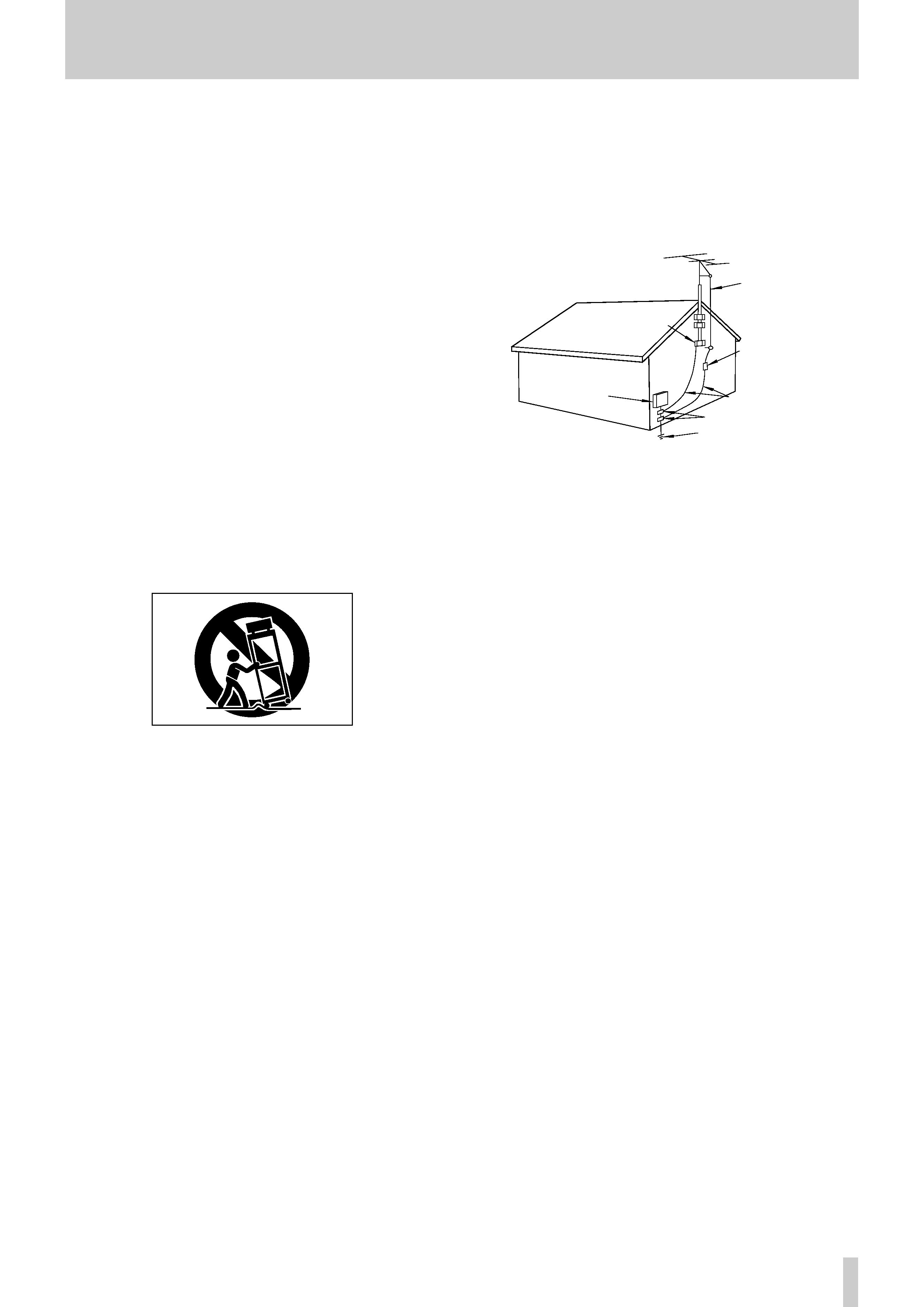
14) Outdoor Antenna Grounding -- If an outside antenna or cable
system is connected to the product, be sure the antenna or cable system is
grounded so as to provide some protection against voltage surges and built-
up static charges. Article 810 of the National Electrical Code, ANSI/NFPA
70, provides information with regard to proper grounding of the mast and
supporting structure, grounding of the lead-in wire to an antenna discharge
unit, size of grounding conductors, location of antenna-discharge unit, con-
nection to grounding electrodes, and requirements for the grounding elec-
trode.
"Note to CATV system installer:
This reminder is provided to call the CATV system installer's attention to
Section 820-40 of the NEC which provides guidelines for proper grounding
and, in particular, specifies that the cable ground shall be connected to the
grounding system of the building, as close to the point of cable entry as
practical.
15) Lightning -- For added protection for this product during a lightning
storm, or when it is left unattended and unused for long periods of time,
unplug it from the wall outlet and disconnect the antenna or cable system.
This will prevent damage to the product due to lightning and power-line
surges.
16) Power Lines -- An outside antenna system should not be located in
the vicinity of overhead power lines or other electric light or power circuits,
or where it can fall into such power lines or circuits. When installing an
outside antenna system, extreme care should be taken to keep from touch-
ing such power lines or circuits as contact with them might be fatal.
17) Overloading -- Do not overload wall outlets, extension cords, or
integral convenience receptacles as this can result in risk of fire or electric
shock.
18) Object and Liquid Entry -- Never push objects of any kind into
this product through openings as they may touch dangerous voltage points
or short-out parts that could result in a fire or electric shock. Never spill
liquid of any kind on the product.
19) Servicing -- Do not attempt to service this product yourself as open-
ing or removing covers may expose you to dangerous voltage or other
hazards. Refer all servicing to qualified service personnel.
20) Damage Requiring Service -- Unplug this product from the wall
outlet and refer servicing to qualified service personnel under the following
conditions:
a) when the power-supply cord or plug is damaged.
b) if liquid has been spilled, or objects have fallen into the product.
c) if the product has been exposed to rain or water.
d) if the product does not operate normally by following the operating
instructions. Adjust only those controls that are covered by the operating
instructions as an improper adjustment of other controls may result in
damage and will often require extensive work by a qualified technician to
restore the product to its normal operation.
e) if the product has been dropped or damaged in any way.
f ) when the product exhibits a distinct change in performance this
indicates a need for service.
21) Replacement Parts -- When replacement parts are required, be
sure the service technician has used replacement parts specified by the
manufacturer or have the same characteristics as the original part.
Unauthorized substitutions may result in fire, electric shock, or other
hazards.
22) Safety Check -- Upon completion of any service or repairs to this
product, ask the service technician to perform safety checks to determine
that the product is in proper operating condition.
23) Wall or Ceiling Mounting -- The product should be mounted to a
wall or ceiling only as recommended by the manufacturer.
24) Heat -- The product should be situated away from heat sources such
as radiators, heat registers, stoves, or other products (including amplifiers)
that produce heat.
ANTENNA
LEAD IN
WIRE
ANTENNA
DISCHARGE UNIT
(NEC SECTION 810-20)
G
ROUNDING CONDUCTORS
(NEC SECTION 810-21)
GROUND CLAMPS
POWER SERVICE GROUNDING
ELECTRODE SYSTEM
(NEC ART 250. PART H)
NEC - NATIONAL ELECTRICAL CODE
ELECTRIC
SERVICE
EQUIPMENT
Example of Antenna Grounding as per
National Electrical Code, ANSI/NFPA 70
GROUND
CLAMP
IMPORTANT SAFETY INSTRUCTIONS

Table of Contents
4 TASCAM DA-78HR
1 - Introduction to the DA-78HR
1.1 Unpacking ......................................... 7
1.2 Features............................................. 7
1.3 Using this manual............................. 7
1.4 Precautions and recommendations 8
1.4.1 Clock source in a digital studio....... 8
1.4.2 HR recording and emphasis ............ 8
1.4.3 Environmental conditions ................ 8
1.4.4 Installing the DA-78HR ..................... 9
1.4.5 Electrical considerations ................. 9
1.4.6 Three-core power cord ..................... 9
1.4.7 Powering the DA-78HR off and on... 9
1.4.8 Condensation .................................... 9
1.5 Recommended tapes........................ 9
1.5.1 Tape brands....................................... 10
1.5.2 Available recording and playback
time........................................................... 11
2 - Front and rear panel features
2.1 General controls and indicators...... 13
1 Power switch ........................................ 13
2 Tape loading slot and EJECT key ...... 13
3 FORMAT/Fs key ................................... 13
4 HR MODE key ....................................... 13
5 CLOCK key ........................................... 13
6 Status indicators .................................. 13
7 Tape counter ........................................ 13
8 PB CONDITION indicator .................... 13
2.2 Tape transport keys and controls ... 13
9 REW key ............................................... 13
A F FWD key ............................................ 13
B STOP key .............................................. 14
C PLAY key .............................................. 14
D RECORD key ........................................ 14
E DATA/LEVEL control ........................... 14
2.3 System control keys......................... 14
F SHIFT key and indicator ...................... 14
G RHSL (DELAY) key and indicator ....... 14
H AUTO IN/OUT (OFFSET) key and
indicator .................................................. 14
I CLEAR (PRE ROLL) key ...................... 14
J VARI SPEED / PITCH key and
indicator .................................................. 14
K ALL INPUT (w) key and indicator ...... 14
L AUTO MON (v) key and indicator ...... 14
M REPEAT (MENU) key and indicator .... 15
N CHASE (SUB MENU) key and
indicator .................................................. 15
O LOC 1 (MEMO 1) key ............................ 15
P LOC 2 (MEMO 2) key ............................ 15
Q MIXDOWN (LEVEL/PAN) key and
indicator .................................................. 15
2.4 Track controls................................... 15
R REC FUNCTION keys and indicators . 15
S Peak meters .......................................... 15
2.5 Rear panel features...........................15
T REMOTE IN/SYNC IN ............................15
U MIDI IN/OUT/THRU ................................15
V SYNC OUT .............................................15
W REMOTE IN ...........................................15
X REMOTE PUNCH IN/OUT .....................16
Y TDIF-1 (DIGITAL I/O) .............................16
Z TIME CODE (IN, OUT) ...........................16
a WORD SYNC (IN, OUT, THRU) ............16
b DIGITAL IN, OUT (COAXIAL) ...............16
c ANALOG INPUTS (unbalanced) ..........16
d ANALOG INPUTS (BALANCED) ..........16
e ANALOG OUTPUTS (unbalanced) ......16
f ANALOG OUTPUTS (BALANCED) ......16
g ~ IN .........................................................16
3 - Connections
3.1 Audio connections............................17
3.1.1 Balanced analog audio connections17
3.1.2 Unbalanced analog audio
connections .............................................17
3.1.3 Digital audio connections.................17
3.1.4 SPDIF connectors..............................18
3.2 Synchronization connections..........18
3.2.1 Word clock connections ...................18
3.2.2 MIDI connectors (IN , OUT and
THRU) .......................................................18
3.2.3 Timecode connections......................18
3.2.4 MIDI timecode connections ..............18
3.3 Connection to other TASCAM units 18
3.3.1 REMOTE IN.........................................18
3.3.2 Footswitch..........................................18
3.3.3 Multiple DTRS units...........................18
3.3.4 "Indirect" word sync .........................19
4 - Menu interface, etc.
4.1 The display ........................................20
4.1.1 Peak meters........................................20
4.2 The SHIFT key ...................................20
4.2.1 Shifted keys........................................20
4.2.2 Shift mode..........................................20
4.3 Menus and sub-menus .....................21
4.3.1 Exiting menu mode............................21
4.3.2 Sub-menus .........................................21
4.3.3 Adjusting parameter values..............21
4.3.4 Resetting parameters to default
values .......................................................21
4.3.5 "Left" and "right" keys......................22
4.3.6 Sub-frame values...............................22
4.3.7 Using the DATA/LEVEL knob to set
values .......................................................22
4.4 SYSTEM menu...................................23
4.5 AUDIO1 menu ....................................23
4.6 AUDIO2 menu ....................................24
4.7 TC menu.............................................24

Table of Contents
TASCAM DA-78HR
5
4.8 TC chase menu..................................25
4.9 TC generator menu ...........................25
4.10 MIDI menu ........................................25
4.11 Maintenance menu..........................26
4.12 Dedicated keys ................................26
5 - Basic operations
5.1 Formatting a tape ..............................27
5.1.1 Selecting a word clock source ........ 27
5.1.2 Formatting......................................... 27
5.1.3 Aborting the format process............ 28
5.1.4 Recording while formatting............. 28
5.2 Recording the first tracks.................28
5.2.1 Preparing to record........................... 28
5.2.2 Selecting a clock source.................. 28
5.2.3 Write-protecting cassettes............... 28
5.2.4 Recording the first tracks (i)............ 29
5.2.5 Recording the basic tracks (ii)......... 29
5.2.6 Replaying the first tracks................. 29
5.3 Input selection ...................................29
5.3.1 Digital input selection....................... 29
5.3.2 Input patchbay routing..................... 30
5.3.3 Track bouncing................................. 30
5.3.4 Returning to ALL ANALOG setting. 31
5.4 More on digital recording .................31
5.4.1 Sampling frequency and word
length ....................................................... 31
5.4.2 Selecting input word length............. 31
5.5 Overdubbing ......................................31
5.6 Punch-in and punch-out ...................32
5.6.1 Automatic punch point setting........ 32
5.6.2 Setting punch points "on the fly".... 32
5.6.3 Setting punch points using the front
panel......................................................... 33
5.6.4 Editing the pre-roll and post-roll
times......................................................... 33
5.6.5 Rehearsing the punch-in.................. 34
5.6.6 Interrupting a rehearsal or punch
recording ................................................. 34
5.6.7 Recording the punch-in.................... 34
5.6.8 Replaying the punched material...... 34
5.6.9 Exiting punch-in mode..................... 35
6 - Monitoring
6.1 ALL INPUT .........................................36
6.2 AUTO MON.........................................36
6.3 Shuttle monitor..................................36
6.3.1 Enabling and disabling shuttle
monitoring ............................................... 36
6.4 Shuttle muting ...................................36
6.5 Summary of monitor modes ............37
7 - Advanced operations
7.1 Autolocation ......................................38
7.1.1 Setting MEMO 1 and MEMO 2 "on
the fly" ......................................................38
7.1.2 Checking, editing and manually
entering MEMO 1 and MEMO 2...............38
7.1.3 Setting the location pre-roll time .....38
7.1.4 Moving to MEMO 1 and MEMO 2 ......38
7.1.5 Location and playback......................38
7.2 Repeat function .................................39
7.2.1 To start repeat play ...........................39
7.3 Track delay.........................................39
7.4 Sub-mixer...........................................40
7.4.1 Entering mixdown mode ...................40
7.4.2 Setting the master level ....................40
7.4.3 Leaving edit/pan setting mode .........40
7.4.4 Setting levels and pan positions......40
7.4.5 Setting the sub-mixer input sources41
7.5 Crossfade times ................................41
7.6 Vari speed (pitch control).................41
7.6.1 To set a non-standard speed............41
7.7 Shuttle operations.............................42
7.7.1 Shuttle monitoring.............................42
7.7.2 Shuttle muting ...................................42
7.8 Meter modes......................................42
7.8.1 Peak hold time ...................................42
7.8.2 Meter ballistics...................................42
7.9 Sine oscillator....................................43
7.9.1 Recording the oscillator ...................43
7.10 REC MUTE (recording silence) ......43
7.11 Dither ................................................43
7.11.1 Selecting dither settings.................44
7.12 Advanced output options...............44
7.12.1 Output word length .........................44
7.12.2 Output patchbay ..............................44
7.13 Emulation .........................................45
7.14 Saving settings to tape...................45
7.15 Restoring settings from tape .........45
8 - Synchronization with other DTRS
units
8.1 Synchronization connections..........47
8.2 Machine ID and master/slave
settings..................................................47
8.2.1 Differences between DTRS models .47
8.2.2 Setting machine ID ............................48
8.2.3 Master/slave settings (CHASE
mode)........................................................48
8.3 Machine offset...................................48
8.3.1 Setting machine offset......................48
8.3.2 Cancelling machine offset ................48
8.3.3 Setting machine offset "on the fly" .49
8.3.4 An example of setting offsets ..........49
8.4 Digital dubbing..................................50
8.5 Synchronized formatting..................50