1
CD
Model Name Using Similar Mechanism CFD-222
Section
CD Mechanism Type
KSM-213CDM
Optical Pick-up Name
KSS-213C
TC
Model Name Using Similar Mechanism NEW
Section Tape Transport Mechanism Type
MF-107
SERVICE MANUAL
US Model
Canadian Model
Australian Model
PMC-107
PERSONAL COMPONENT SYSTEM
CD player section
System
Compact disc digital audio system
Laser diode properties
Material: GaAlAs
Wave length: 780 nm
Emission duration: Continuous
Laser output: Less than 44.6 µW
(This output is the value measured at a distance of
about 200 mm from the objective lens surface on
the optical pick-up block with 7 mm aperture.)
Spindle speed
200 r/min (rpm) to 500 r/min (rpm) (CLV)
Number of channels
2
Frequency response
20 - 20,000 Hz +1/2 dB
Wow and flutter
Below measurable limit
Radio section
Frequency range
FM
87.6 - 108 MHz
AM
Australian model
531 - 1,602 kHz
US, Canadian model
530 - 1,710 kHz
IF
FM: 10.7 MHz
AM: 450 kHz
Aerials
FM: Wire aerial
AM: External aerial
Continued on next page
Cassette-corder section
Recording system
4-track 2 channel stereo
Fast winding time
Approx. 120 s (sec.) with Sony cassette C-60
Frequency response
TYPE I (normal): 70 - 10,000 Hz
General
Speaker
Full range: 10 cm (4 in.) dia.,
3 ohms, cone type (2)
Outputs
Headphones jack (stereo minijack)
For 16 - 68 ohms impedance headphones
Maximum power output (excluding US model)
4.5 W + 4.5 W
Power requirements
For personal component system:
US, Canadian model:
120 V AC, 60 Hz
Australian model:
230 V AC, 50 Hz
For remote control:
3 V DC, 2 size AA (R6) batteries
Power consumption
US, Canadian model: 18 W
Australian model: 23 W
SPECIFICATIONS
AUDIO POWER SPECIFICATIONS (US model)
POWER OUTPUT AND TOTAL
HARMONIC DISTORTION
With 3-ohm loads, both channels driven from
150 - 10,000 Hz; rated 4.2 W per channel-
minimum RMS power, with no more than
10 % total harmonic distortion in AC
operation.
MICROFILM
Ver 1.1 2000. 02
2
Dimensions (incl. projecting parts)
Player : Approx. 160
× 245 × 215 mm (w/h/d)
(6 3/8
× 9 3/4 × 8 1/2 inches)
Speaker : Approx. 150
× 245 × 175 mm (w/h/d)
(6
× 9 3/4 × 7 inches)
Mass
Player : Approx. 2.6 kg (5 lb. 12 oz.)
Speaker : Approx. 1.1 kg (2 lb. 7 oz.)
Supplied accessories
Remote control (1)
AM loop aerial (1)
Design and specifications are subject to change without
notice.
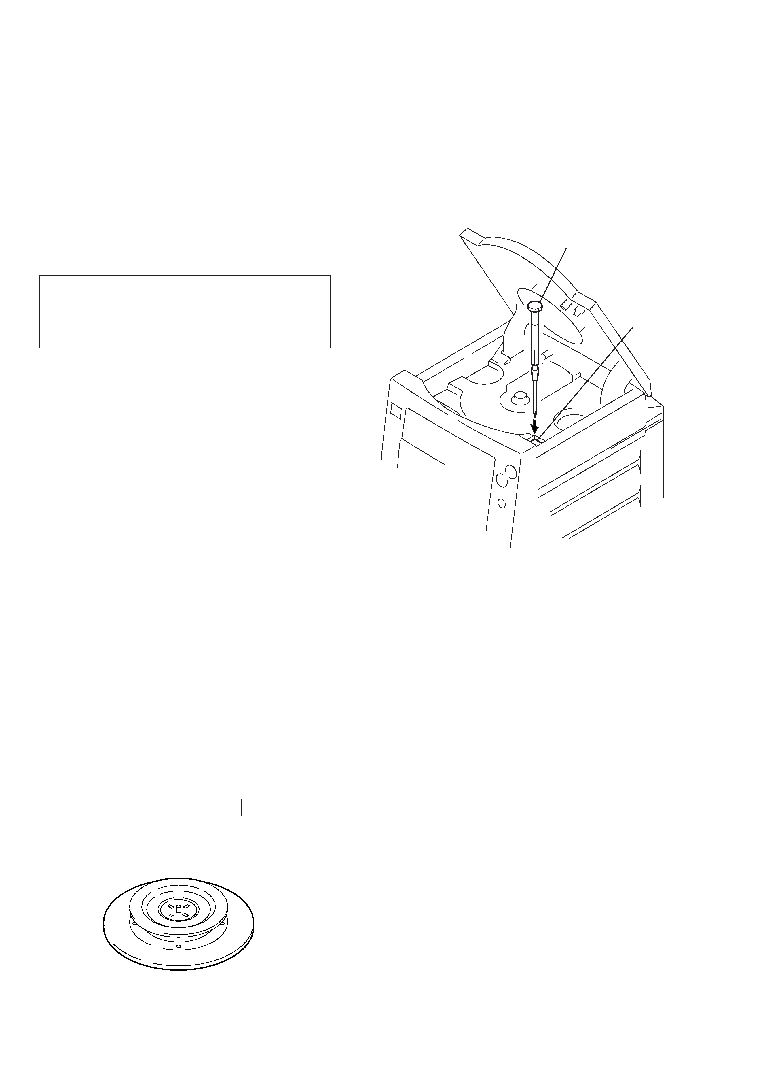
LASER DIODE AND FOCUS SEARCH OPERATION
CHECK
1. Open the CD lid.
2. Push on PUSH SWITCH (SW701) as following figure.
3. Confirm the laser diode emission while observing the objecting
lens. When there is no emission, Auto Power Control circuit or
Optical Pick-up is broken.
Objective lens moves up and down once for the focus search.
Push on SW701 in the
arrowed direction with
a screwdriver, etc.
SW701
CAUTION
Use of controls or adjustments or performance of proce-
dures other than those specified herein may result in haz-
ardous radiation exposure.
Flexible Circuit Board Repairing
· Keep the temperature of the soldering iron around 270°C during
repairing.
· Do not touch the soldering iron on the same conductor of the
circuit board (within 3 times).
· Be careful not to apply force on the conductor when soldering
or unsoldering.
Notes on Chip Component Replacement
· Never reuse a disconnected chip component.
· Notice that the minus side of a tantalum capacitor may be dam-
aged by heat.
NOTES ON HANDLING THE OPTICAL PICK-UP BLOCK
OR BASE UNIT
The laser diode in the optical pick-up block may suffer electrostatic
breakdown because of the potential difference generated by the
charged electrostatic load, etc. on clothing and the human body.
During repair, pay attention to electrostatic breakdown and also use
the procedure in the printed matter which is included in the repair
parts.
The flexible board is easily damaged and should be handled with
care.
NOTES ON LASER DIODE EMISSION CHECK
The laser beam on this model is concentrated so as to be focused on
the disc reflective surface by the objective lens in the optical pick-
up block. Therefore, when checking the laser diode emission,
observe from more than 30 cm away from the objective lens.
CHUCK PLATE JIG ON REPAIRING
On repairing CD section, playing a disc without the CD lid, use
Chuck Plate jig.
· Part No. of Chuck Plate jig : X-4918-255-1
SAFETY-RELATED COMPONENT WARNING!!
COMPONENTS IDENTIFIED BY MARK
! OR DOTTED LINE
WITH MARK
! ON THE SCHEMATIC DIAGRAMS AND IN
THE PARTS LIST ARE CRITICAL TO SAFE OPERATION.
REPLACE THESE COMPONENTS WITH SONY PARTS WHOSE
PART NUMBERS APPEAR AS SHOWN IN THIS MANUAL OR
IN SUPPLEMENTS PUBLISHED BY SONY.
ATTENTION AU COMPOSANT AYANT RAPPORT
À LA SÉCURITÉ!!
LES COMPOSANTS IDENTIFIÉS PAR UNE MARQUE
! SUR LES
DIAGRAMMES SCHÉMATIQUES ET LA LISTE DES PIÈCES
SONT CRITIQUES POUR LA SÉCURITÉ DE FONCTIONNEMENT.
NE REMPLACER CES COMPOSANTS QUE PAR DES PIÈCES
SONY DONT LES NUMÉROS SONT DONNÉS DANS CE MANUEL
OU DANS LES SUPPLÉMENTS PUBLIÉS PAR SONY.
3
TABLE OF CONTENTS
1. GENERAL
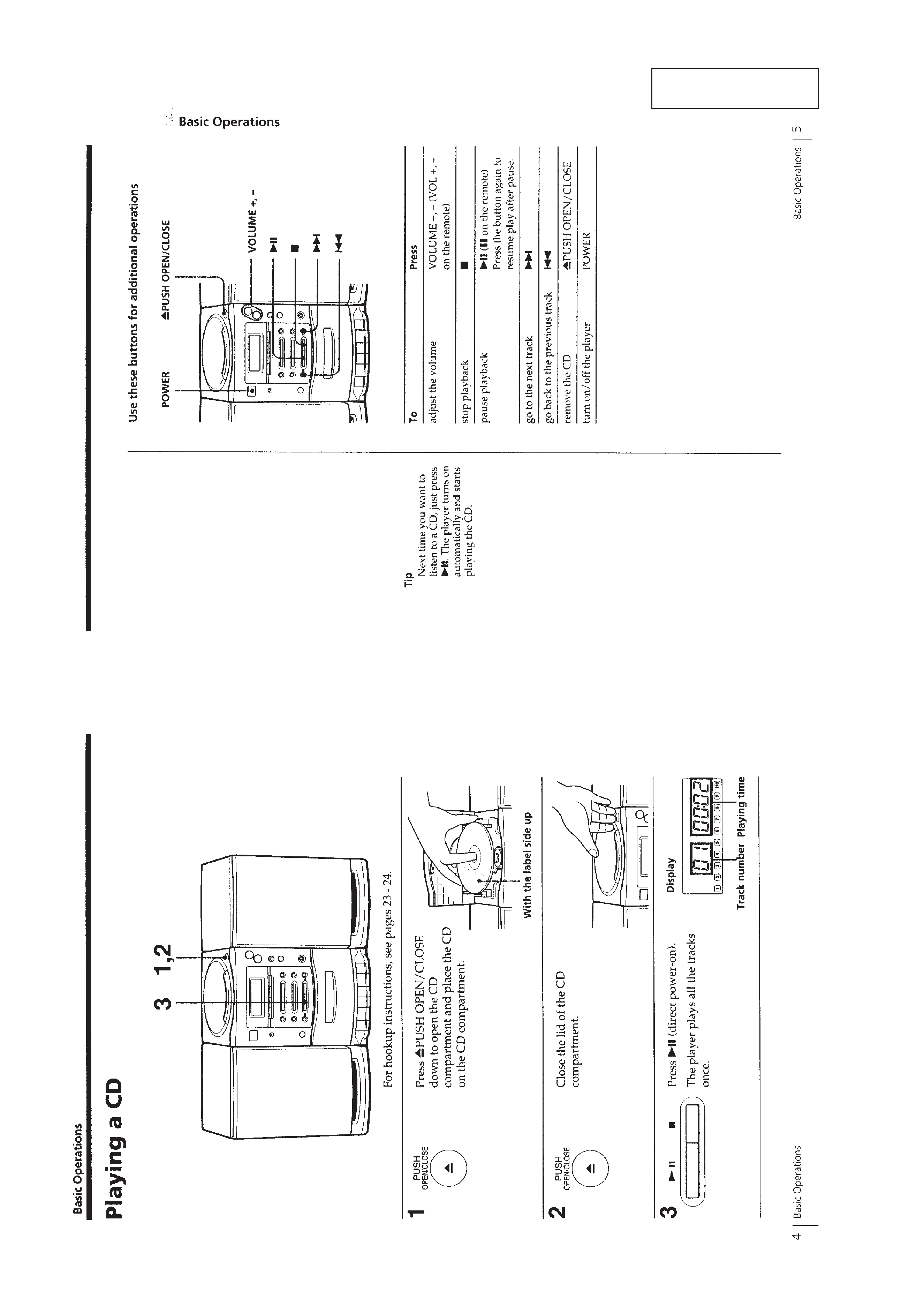
Playing a CD ........................................................................... 4
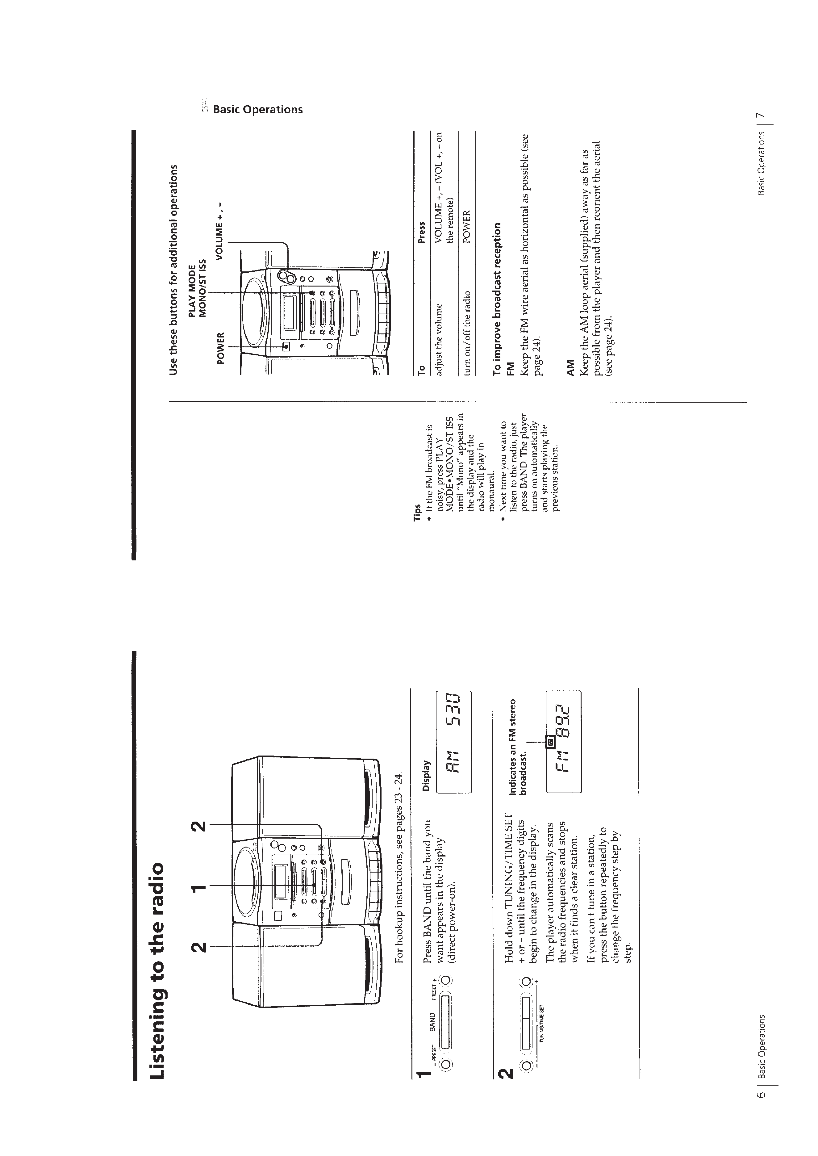
Listening to the radio ............................................................... 5
Playing a tape .......................................................................... 6
Recording on a tape ................................................................. 7
2. DISASSEMBLY
2-1. Front Cabinet Assy .............................................................. 8
2-2. CD Chassis Assy ................................................................. 9
2-3. Power Board ........................................................................ 9
2-4. Main Board ....................................................................... 10
2-5. CD Board .......................................................................... 10
2-6. Optical Pick-up ................................................................. 11
2-7. Mechanism Deck Block .................................................... 11
2-8. Control Board .................................................................... 12
3. MECHANICAL ADJUSTMENTS ............................... 13
4. ELECTRICAL ADJUSTMENTS
Tape Section .......................................................................... 13
Tuner Section ......................................................................... 14
CD Section ............................................................................ 16
5. DIAGRAMS
5-1. IC Pin Description ............................................................. 20
5-2. Circuit Boards Location .................................................... 22
5-3. Block Diagram CD Section ........................................... 23
5-4. Block Diagram Main Section ........................................ 25
5-5. Printed Wiring Boards CD Section ............................... 27
5-6. Schematic Diagram CD Section .................................... 29
5-7. Printed Wiring Boards Main Section ............................ 33
5-8. Schematic Diagram Main Section (1/2) ........................ 35
5-9. Schematic Diagram Main Section (2/2) ........................ 37
5-10. Printed Wiring Boards Panel Section ............................ 40
5-11. Schematic Diagram Panel Section ................................ 42
6. EXPLODED VIEWS
6-1. Rear Cabinet Section ......................................................... 48
6-2. Front Cabinet Section ........................................................ 49
6-3. Upper Cabinet Section ...................................................... 50
6-4. Cassette Mechanism Section-1 ......................................... 51
6-5. Cassette Mechanism Section-2 ......................................... 52
6-6. Cassette Mechanism Section-3 ......................................... 53
6-7. Cassette Mechanism Section-4 ......................................... 54
6-8. Optical Pick-up Section .................................................... 55
6-9. Speaker Section ................................................................. 56
7. ELECTRICAL PARTS LIST ........................................ 57
SAFETY CHECK-OUT
After correcting the original service problem, perform the following
safety check before releasing the set to the customer:
Check the antenna terminals, metal trim, "metallized" knobs, screws,
and all other exposed metal parts for AC leakage. Check leakage as
described below.
LEAKAGE TEST
The AC leakage from any exposed metal part to earth ground and
from all exposed metal parts to any exposed metal part having a
return to chassis, must not exceed 0.5 mA (500 microamperes).
Leakage current can be measured by any one of three methods.
1. A commercial leakage tester, such as the Simpson 229 or RCA
WT-540A. Follow the manufacturers' instructions to use these
instruments.
2. A battery-operated AC milliammeter. The Data Precision 245
digital multimeter is suitable for this job.
3. Measuring the voltage drop across a resistor by means of a VOM
or battery-operated AC voltmeter. The "limit" indication is 0.75
V, so analog meters must have an accurate low-voltage scale. The
Simpson 250 and Sanwa SH-63Trd are examples of a passive
VOM that is suitable. Nearly all battery operated digital
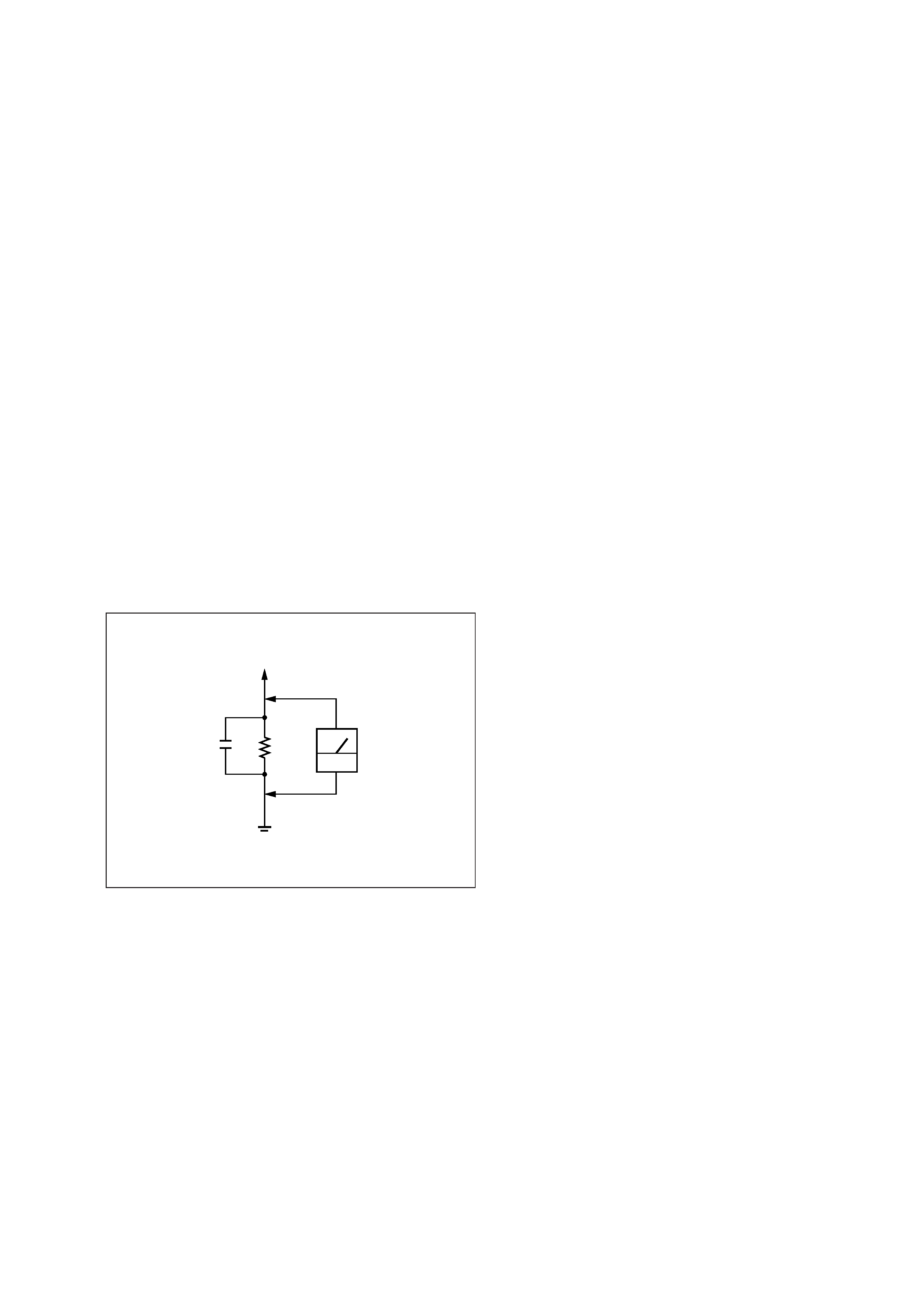
multimeters that have a 2V AC range are suitable. (See Fig. A)
Fig. A. Using an AC voltmeter to check AC leakage.
To Exposed Metal
Parts on Set
1.5k
0.15
µF
AC
voltmeter
(0.75V)
Earth Ground
4
SECTION 1
GENERAL
This section is extracted
from instruction manual.
5