MICROFILM
SERVICE MANUAL
SOUND-SENSOR NURSERY MONITOR
US Model
E Model
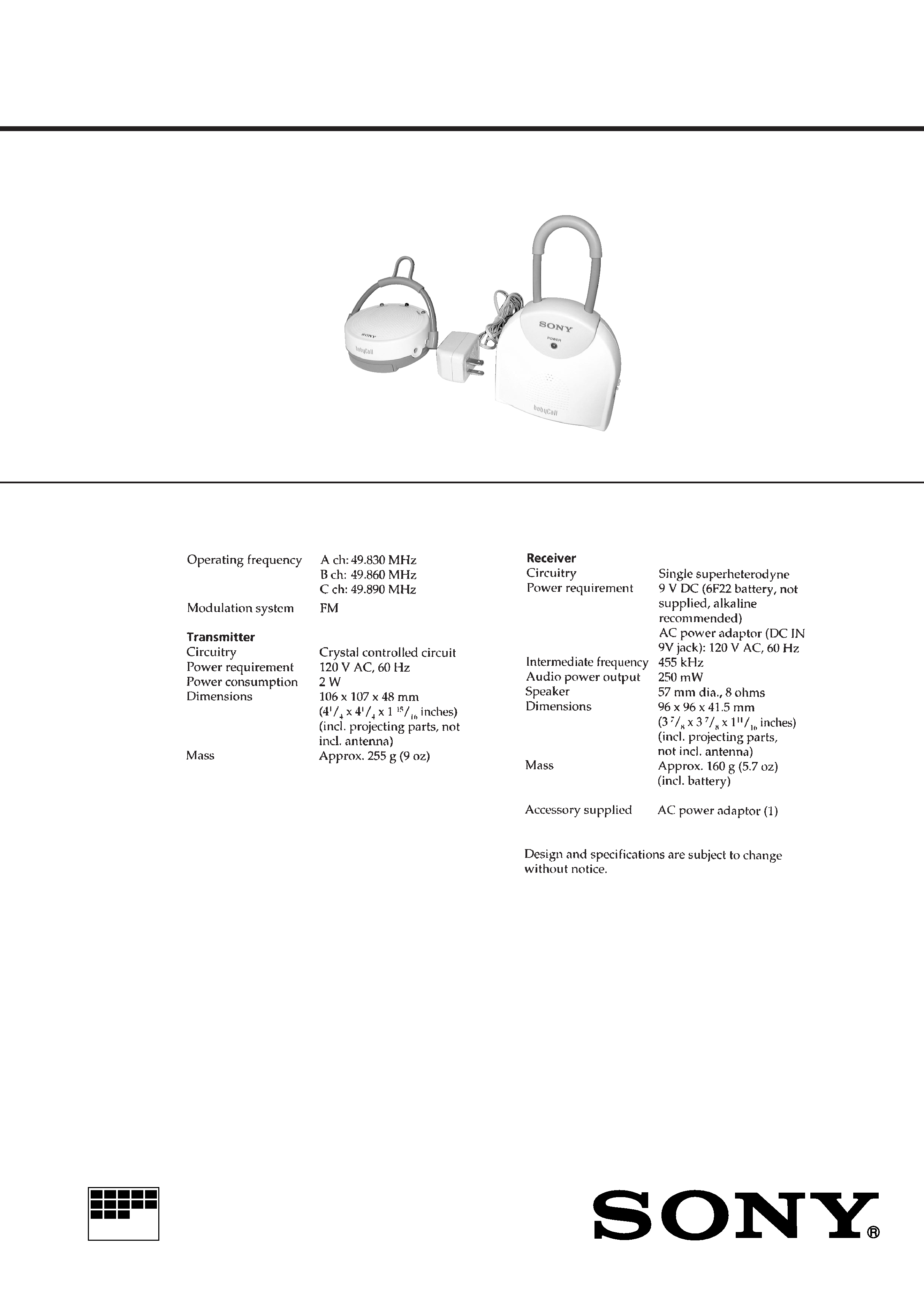
SPECIFICATIONS
NTM-30
Receiver
Transmitter
Ver 1.0 1999. 03
2
TABLE OF CONTENTS
1.
GENERAL ................................................................... 3
2.
DISASSEMBLY ......................................................... 4
3.
ELECTRICAL ADJUSTMENTS ......................... 6
4.
DIAGRAMS
4-1. Block Diagram ................................................................
9
4-2. Schematic Diagram TX/MIC Boards ....................... 11
4-3. Printed Wiring Board TX/MIC Boards ................... 13
4-4. Printed Wiring Board RX Board ............................. 14
4-5. Schematic Diagram RX Board ................................ 15
5.
EXPLODED VIEWS ................................................ 17
6.
ELECTRICAL PARTS LIST ............................... 19
SAFETY-RELATED COMPONENT WARNING!!
COMPONENTS IDENTIFIED BY MARK
! OR DOTTED
LINE WITH MARK
! ON THE SCHEMATIC DIAGRAMS
AND IN THE PARTS LIST ARE CRITICAL TO SAFE
OPERATION. REPLACE THESE COMPONENTS WITH
SONY PARTS WHOSE PART NUMBERS APPEAR AS
SHOWN IN THIS MANUAL OR IN SUPPLEMENTS PUB-
LISHED BY SONY.
Notes on chip component replacement
· Never reuse a disconnected chip component.
· Notice that the minus side of a tantalum capacitor may be dam-
aged by heat.
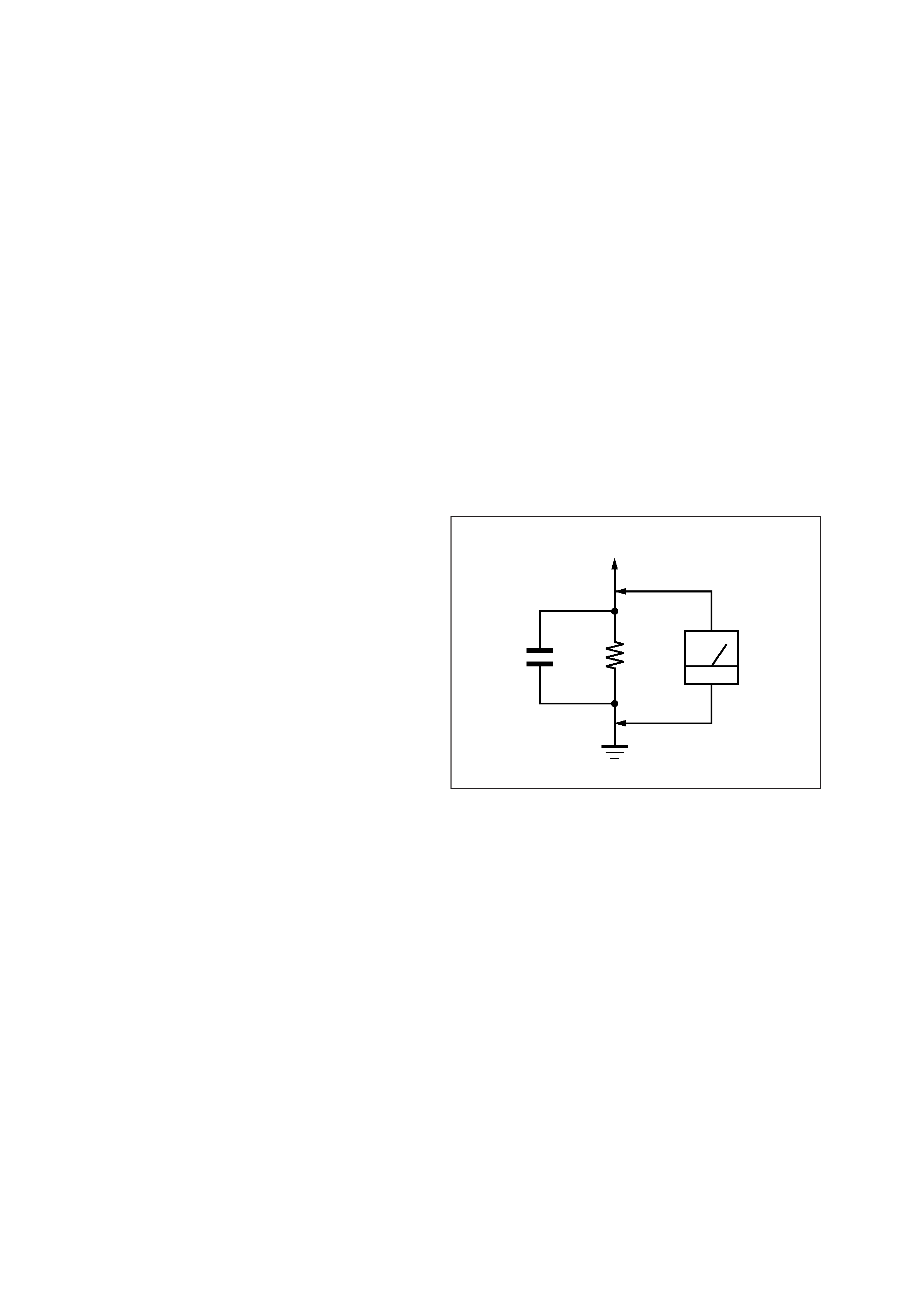
SAFETY CHECK-OUT
After correcting the original service problem, perform the follow-
ing safety check before releasing the set to the customer:
Check the antenna terminals, metal trim, "metallized" knobs,
screws, and all other exposed metal parts for AC leakage.
Check leakage as described below.
LEAKAGE TEST
The AC leakage from any exposed metal part to earth ground and
from all exposed metal parts to any exposed metal part having a
return to chassis, must not exceed 0.5 mA (500 microampers.).
Leakage current can be measured by any one of three methods.
1. A commercial leakage tester, such as the Simpson 229 or RCA
WT-540A. Follow the manufacturers' instructions to use these
instruments.
2. A battery-operated AC milliammeter. The Data Precision 245
digital multimeter is suitable for this job.
3. Measuring the voltage drop across a resistor by means of a
VOM or battery-operated AC voltmeter. The "limit" indica-
tion is 0.75 V, so analog meters must have an accurate low-
voltage scale. The Simpson 250 and Sanwa SH-63Trd are ex-
amples of a passive VOM that is suitable. Nearly all battery
operated digital multimeters that have a 2 V AC range are suit-
able. (See Fig. A)
Fig. A.
Using an AC voltmeter to check AC leakage.
1.5 k
0.15
µF
AC
voltmeter
(0.75 V)
To Exposed Metal
Parts on Set
Earth Ground
3
SECTION 1
GENERAL
This section is extracted from
instruction manual.
4
· TRANSMITTER SECTION
REAR CABINET
AC ADAPTER CORD SETTING
Wind the AC adaptor cord to boss 2 time.
Note: Follow the disassembly procedure in the numerical order given.
SECTION 2
DISASSEMBLY
1 two screws
(P2.6
× 12)
1 two screws
(P2.6
× 12)
2 rear cabinet
AC adaptor cord
boss
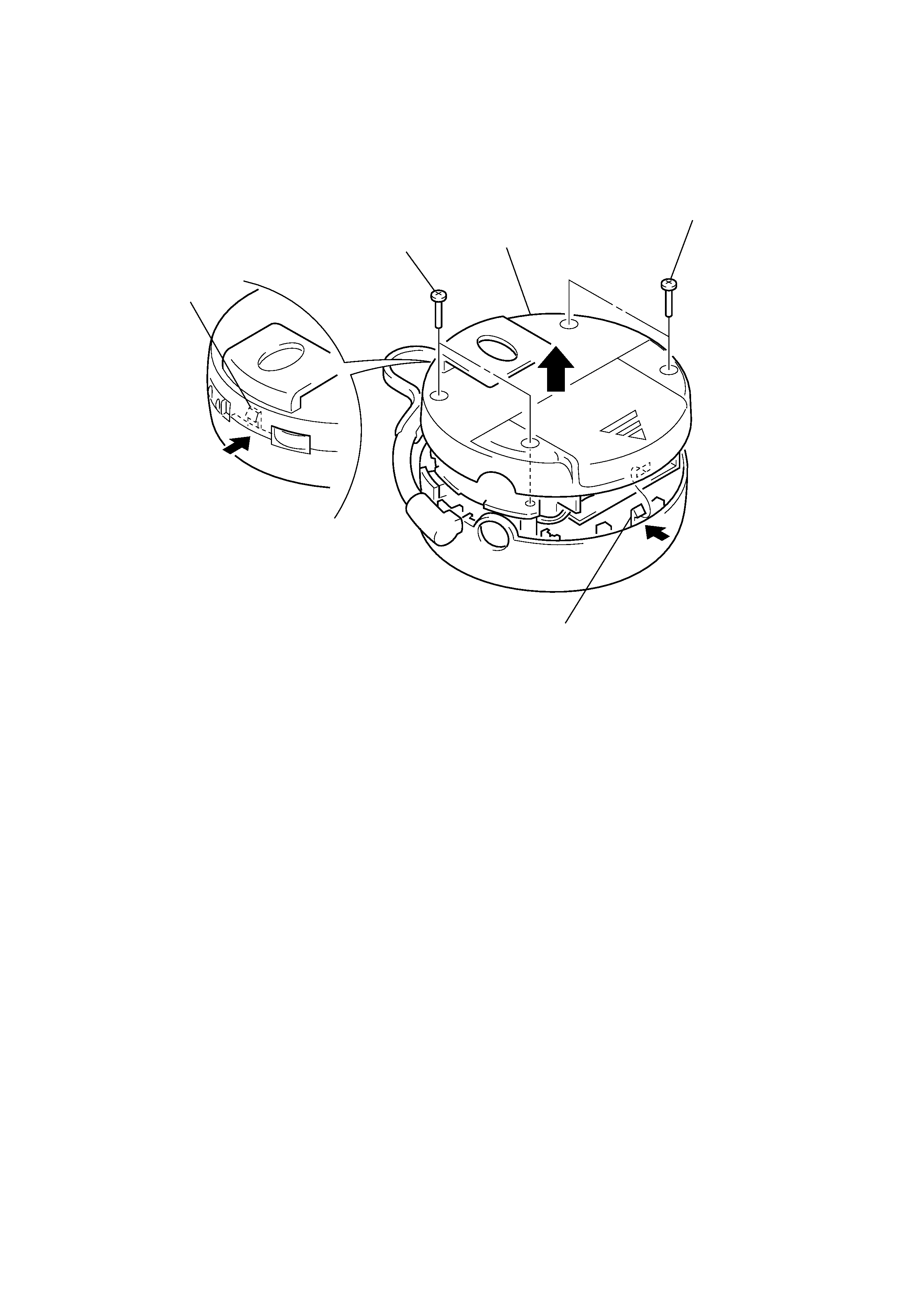
5
· RECEIVER SECTION
LOWER CABINET
2 claw
2 claw
1 two screws
(P2.6
× 12)
1 two screws
(P2.6
× 12)
3 lower cabinet