Ver 1.1 2001.01
MZ-E900
SERVICE MANUAL
PORTABLE MINIDISC PLAYER
SPECIFICATIONS
US Model
Canadian Model
AEP Model
UK Model
E Model
Tourist Model
Model Name Using Similar Mechanism
NEW
MD Mechanism Type
MT-MZE900-173
Optical Pick-up Mechanism Type
LCX-4E
US and foreign patents licensed from Dolby
Laboratories Licensing Corporation
System
Audio playing system
MiniDisc digital audio system
Laser diode properties
Material: GaAlAs
Wavelength: l = 790 nm
Emission duration: continuous
Laser output: less than 44.6
µW*
* This output is the value measured at a distance of 200 mm from
the objective lens surface on the optical pick-up block with 7 mm
aperture.
Revolutions
Approx. 300 rpm to 2,700 rpm
Error correction
ACIRC (Advanced Cross Interleave Reed Solomon Code)
Sampling frequency
44.1 kHz
Coding
ATRAC (Adaptive TRansform Acoustic Coding)
ATRAC3: LP2
ATRAC3: LP4
Modulation system
EFM (Eight to Fourteen Modulation)
Number of channels
2 stereo channels
1 monaural channel
Frequency response
20 to 20,000 Hz
± 3 dB
Wow and Flutter
Below measurable limits
Outputs
Headphones/earphones: stereo mini-jack, maximum output level 5
mW +5 mW, load impedance 16 ohms
Power requirements
Nickel metal hydride rechargeable battery
One NH-14WM(A) (supplied): 1.2V, 1,350 mAh (min)
One LR6 (size AA) battery (not supplied)
External power jack: Power rating 1.5V DC
Battery operation time 1) 2)
Batteries
Stereo(normal)
LP2 Stereo
LP4 Stereo
Ni-MH rechargeable
29
33
37
battery
NH-14WM (A) 1)
LR6 (SG) Sony
42
49
58
alkaline dry battery 3)
LR6 (SG) Sony
76
87
100
alkaline dry battery 3)
and a Ni-MH rechargeable
rechargeable battery 1)
Unit:Approx. hours
1) With a fully charged battery
2) Measured in accordance with the EIAJ (Electronic Industries
Association of Japan) standard (using a Sony MDW-series Mini-disc).
3) When using a Sony LR6 (SG) "STAMINA" alkaline dry battery
(produced in Japan).
Note
The battery life may be shorter depending on operating conditions, the
surrounding temperature, and the battery type.
Dimensions
Approx. 77.7 x 12.7 x 71.0 mm (w/h/d) (3 1/8 x
1/
2 x 2
7/
8 in.)
(not including projecting parts and controls)
Mass
Approx. 58g (2.0 oz) (the player only)
Supplied accessories
Headphones/earphones with a remote control (1)
Battery charger (1) (EXCEPT Korean MODEL)
Rechargeable battery (1)
Rechargeable battery carrying case (1) (Tourist MODEL)
Dry battery case (1)
Carrying pouch (1) (EXCEPT US MODEL)
AC plug adaptor (1) (E33, Tourist model)
Design and specifications are subject to change without notice.
9-927-992-12
2001A0200-1
© 2001.1
Sony Corporation
Audio Entertainment Group
General Engineering Dept.
2
MZ-E900
Specifications ........................................................................... 1
1. SERVICING NOTE ...................................................... 2
2. GENERAL
Location and Function of Controls .................................... 3
3. DISASSEMBLY
3-1. "Lid ASSY, Upper", Holder ASSY ............................ 4
3-2. Mechanism Deck ........................................................ 4
3-3. Audio Board ................................................................ 5
3-4. Bracket (L) ASSY, Bracket (R) ASSY ....................... 5
3-5. Main Board, Bracket (L) ASSY, SW Board ............... 6
3-6. Optical Pick-up ASSY ................................................ 6
4. TEST MODE .................................................................. 7
5. ELECTRICAL ADJUSTMENTS ............................ 11
6. DIAGRAMS
6-1. Block Diagram .......................................................... 15
6-2. Printed Wiring Boards Main Section (1/2) ......... 16
6-3. Printed Wiring Boards Main Section (2/2) ......... 17
6-4. Schematic Diagram Main Section (1/2) ............. 18
6-5. Schematic Diagram Main Section (2/2) ............. 19
6-6. Printed Wiring Boards Audio Section ................ 20
6-7. Schematic Diagram Audio Section ..................... 21
7. EXPLODED VIEWS
7-1. Front Section ............................................................ 25
7-2. Mechanism Deck Section ......................................... 26
8. ELECTRICAL PARTS LIST ................................... 27
SAFETY-RELATED COMPONENT WARNING!!
COMPONENTS IDENTIFIED BY MARK
! OR DOTTED LINE WITH
MARK
!ON THE SCHEMATIC DIAGRAMS AND IN THE PARTS
LIST ARE CRITICAL TO SAFE OPERATION.
REPLACE THESE COMPONENTS WITH SONY PARTS WHOSE
PART NUMBERS APPEAR AS SHOWN IN THIS MANUAL OR IN
SUPPLEMENTS PUBLISHED BY SONY.
Flexible Circuit Board Repairing
· Keep the temperature of the soldering iron around 270
°C during
repairing.
· Do not touch the soldering iron on the same conductor of the
circuit board (within 3 times).
· Be careful not to apply force on the conductor when soldering or
unsoldering.
Notes on chip component replacement
· Never reuse a disconnected chip component.
· Notice that the minus side of a tantalum capacitor may be dam-
aged by heat.
TABLE OF CONTENTS
SECTION 1
SERVICING NOTE
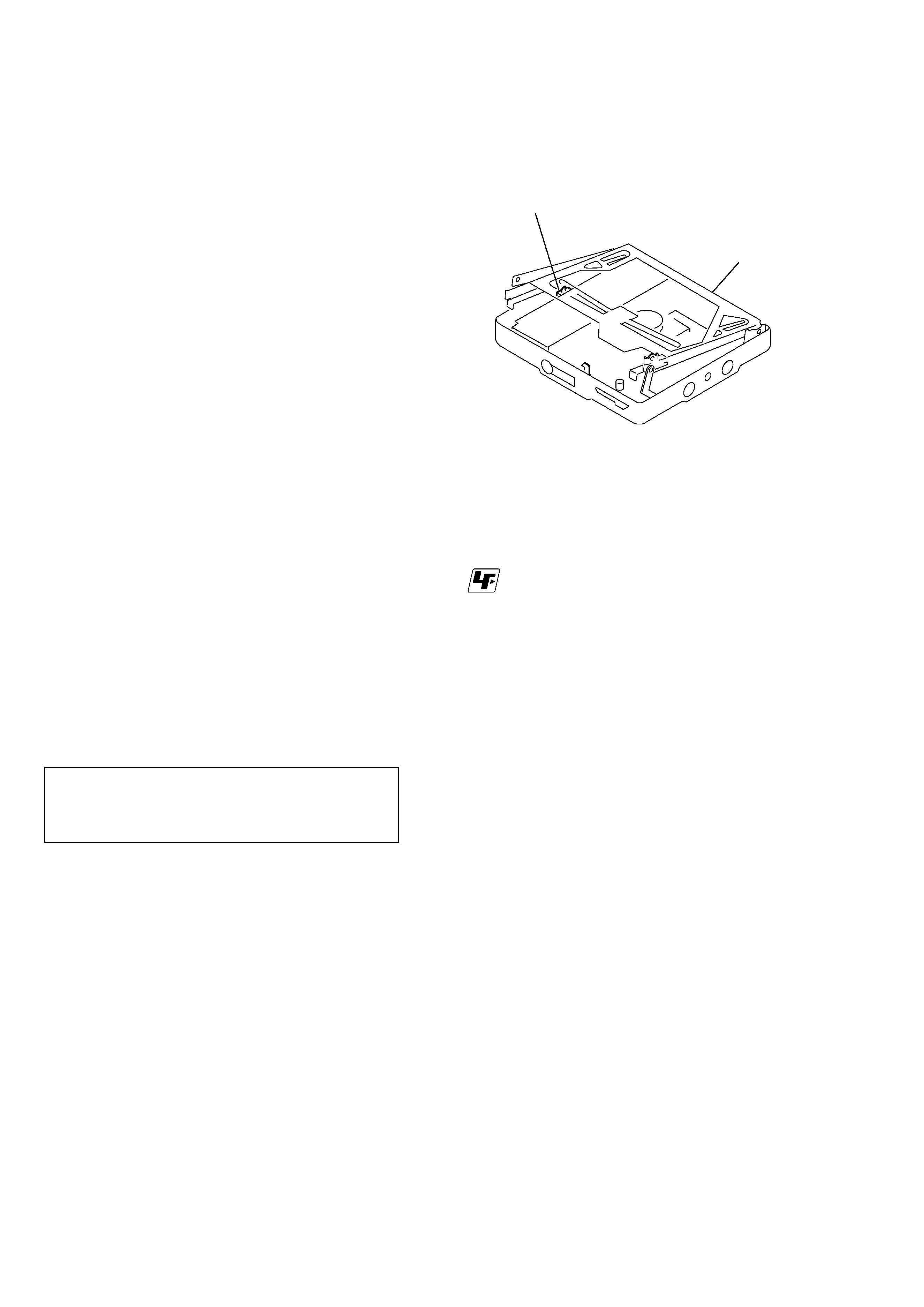
When repairing this device with the power on, if you remove the
main board, this device stops working.
In this case, you work without the device stopping by fastening
the hook of the Open/Close detection switch (S809).
* Replacement of CXD2671-201GA (IC601) used in this set
requires a special tool.
CAUTION
Use of controls or adjustments or performance of procedures
other than those specified herein may result in hazardous
radiation exposure.
Open/Close detection switch (S809)
Mechanism deck section
r
UNLEADED SOLDER
Boards requiring use of unleaded solder are printed with the
lead-free mark (LF) indicating the solder contains no lead.
(Caution: Some printed circuit boards may not come printed
with the lead free mark due to their particular size.)
: LEAD FREE MARK
Unleaded solder has the following characteristics.
· Unleaded solder melts at a temperature about 40
°C higher
than ordinary solder.
Ordinary soldering irons can be used but the iron tip has to
be applied to the solder joint for a slightly longer time.
Soldering irons using a temperature regulator should be set
to about 350
°C.
Caution: The printed pattern (copper foil) may peel away if
the heated tip is applied for too long, so be careful!
· Strong viscosity
Unleaded solder is more viscous (sticky, less prone to
flow) than ordinary solder so use caution not to let solder
bridges occur such as on IC pins, etc.
· Usable with ordinary solder
It is best to use only unleaded solder but unleaded solder
may also be added to ordinary solder.
Ver 1.1 2001.01
3
MZ-E900
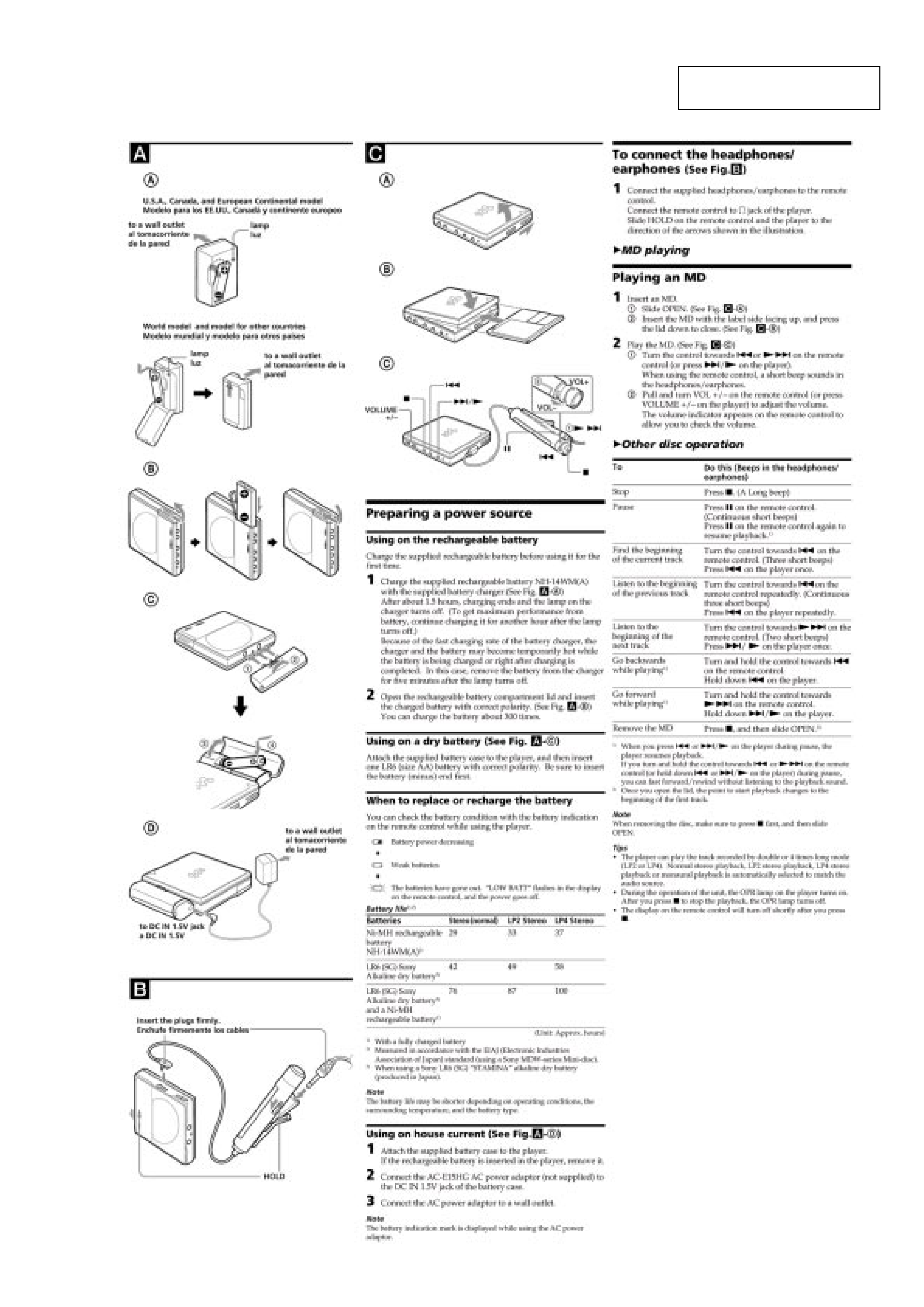
SECTION 2
GENERAL
This section is extracted from
instruction manual.
Ver 1.1 2001.01
4
MZ-E900
SECTION 3
DISASSEMBLY
Note : Follow the disassembly procedure in the numerical order given.
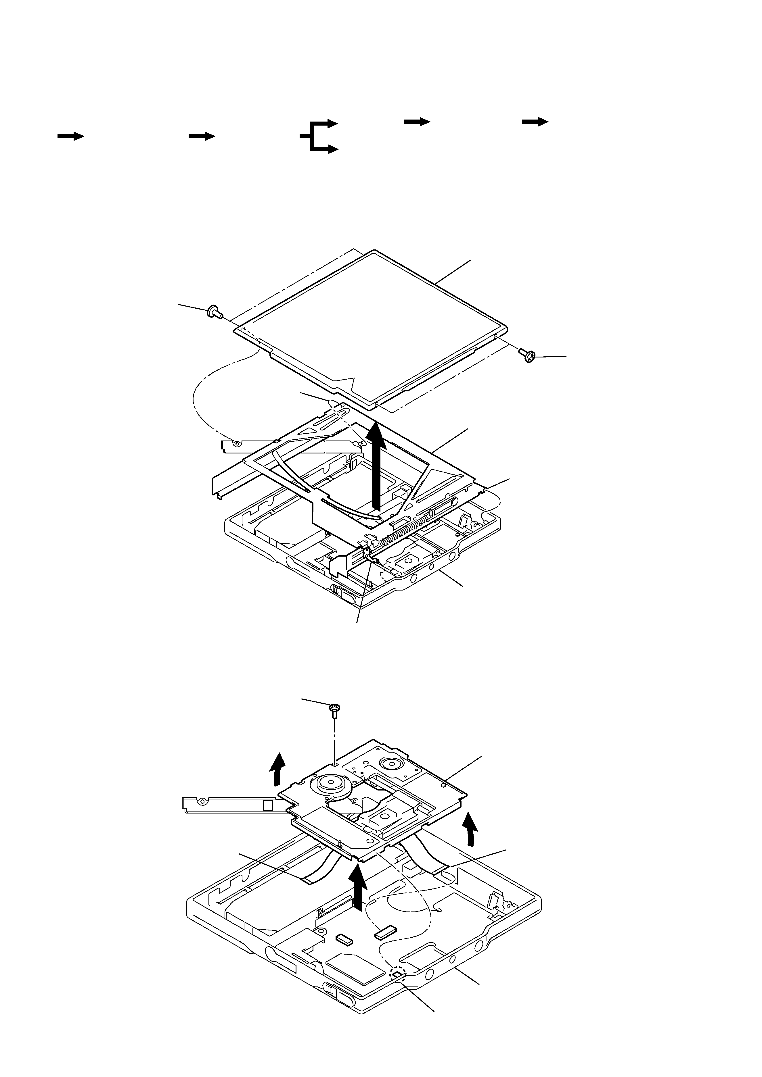
3-1. "LID ASSY, UPPER", HOLDER ASSY
3-2. MECHANISM DECK
r
The equipment can be removed using the following procedure.
Optical pick-up ASSY
Set
"Lid ASSY, Upper",
Holder ASSY
Mechanism deck
Audio board
Main board,
Bracket (L) ASSY,
SW board
Bracket (R) ASSY
1
Screws (MI 1.4)
Panel, bottom
4
Bracket (stop) ASSY
Holder ASSY
3
Move it away
from projection
3
Move it away
from projection
1
Screws (MI 1.4)
2
Lid ASSY, upper
1
Screws (MD), step
Panel, bottom
6
Motor flexible board
7
OP flexible board
4
Claw
2
5
3
Mechanism deck
5
MZ-E900
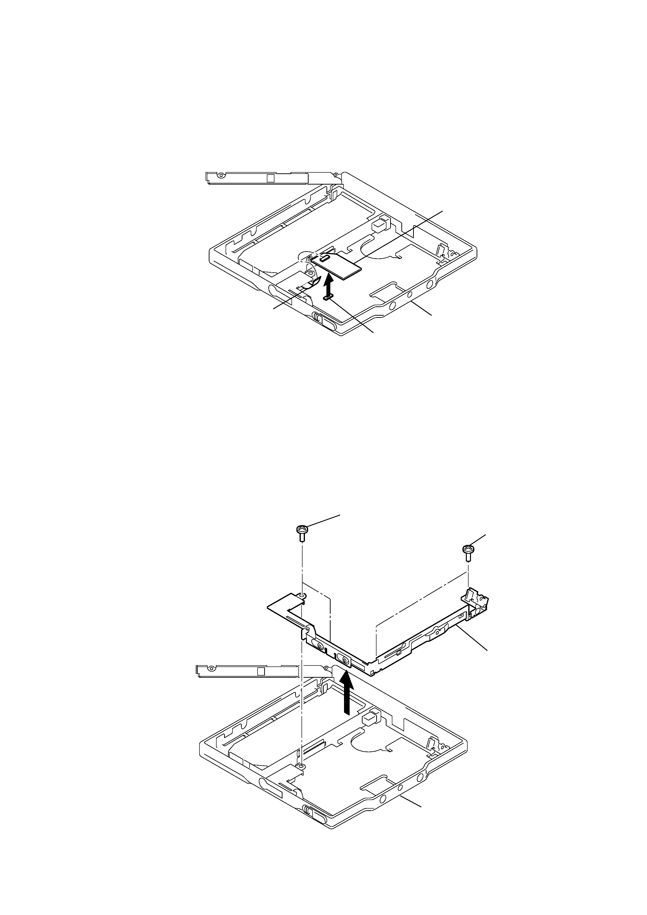
3-3. AUDIO BOARD
3-4. BRACKET (R) ASSY
Panel, bottom
2
CN801
1
Switch flexible board
Audio board
1
Screws (MI 1.4)
2
Screws (MI 1.4)
3
Bracket (R) ASSY
Panel, bottom
Ver 1.1 2001.01