M-200MC
SERVICE MANUAL
MICROCASSETTETM-CORDER
SPECIFICATIONS
Ver 1.1 2002. 01
Model Name Using Similar Mechanism
NEW
Tape Transport Mechanism Type
MZ-200MC-99
US Model
Canadian Model
AEP Model
E Model
Chinese Model
Tape
(normal position type)
Recording system
2-track 1-channel monaural
Speaker
Approx. 2.8 cm (11/8 in.) dia.
Tape speed
2.4 cm/s (15/16 ips), 1.2 cm/s (15/32 ips)
Frequency range
300 - 4 000 Hz (with TAPE SPEED switch at 2.4 cm)
Output
Earphone jack (minijack) for 8 300
earphone
Power output (at 10% harmonic distortion)
250 mW
Power requirements
3 V DC, two R03 (size AAA) batteries/External DC 3V power sources
Dimensions (w/h/d)
Approx. 27.8
× 127 × 69 mm (11/8 × 5 × 23/4 in.) incl. projecting parts and
controls
Mass
Approx. 140 g (5 oz) (main unit only)
Design and specifications are subject to change without notice.
Sony Corporation
Personal Audio Company
Published by Sony Engineering Corporation
9-873-133-12
2002A1600-1
© 2002.1

2
TABLE OF CONTENTS
M-200MC
Flexible Circuit Board Repairing
· Keep the temperature of the soldering iron around 270°C during
repairing.
· Do not touch the soldering iron on the same conductor of the
circuit board (within 3 times).
· Be careful not to apply force on the conductor when soldering
or unsoldering.
Notes on Chip Component Replacement
· Never reuse a disconnected chip component.
· Notice that the minus side of a tantalum capacitor may be dam-
aged by heat.
1. GENERAL ·········································································· 3
2. DISASSEMBLY ································································ 4
2-1. Lid Assy, Cassette ································································· 4
2-2. Lid Assy, Battery Case ·························································· 4
2-3. Cabinet (Rear) Assy ······························································ 5
2-4. Main Board ··········································································· 5
2-5. Microphone, Built-in C-2038 set ·········································· 6
2-6. Speaker, LED Board ····························································· 6
2-7. Mechanism Deck ·································································· 7
2-8. Head, Ceramic (HRPE901, 902) ··········································· 7
3. MECHANICAL ADJUSTMENTS ······························· 8
4. ELECTRICAL ADJUSTMENTS ································· 8
5. DIAGRAMS ········································································ 9
5-1. Block Diagram ···································································· 10
5-2. Printed Wiring Board ·························································· 11
5-3. Schematic Diagram ····························································· 12
6. EXPLODED VIEWS ······················································ 13
6-1. Cabinet Section ··································································· 13
6-2. Mechanism Deck (1) ··························································· 15
6-3. Mechanism Deck (2) ··························································· 16
7. ELECTRICAL PARTS LIST ······································· 17
3
M-200MC
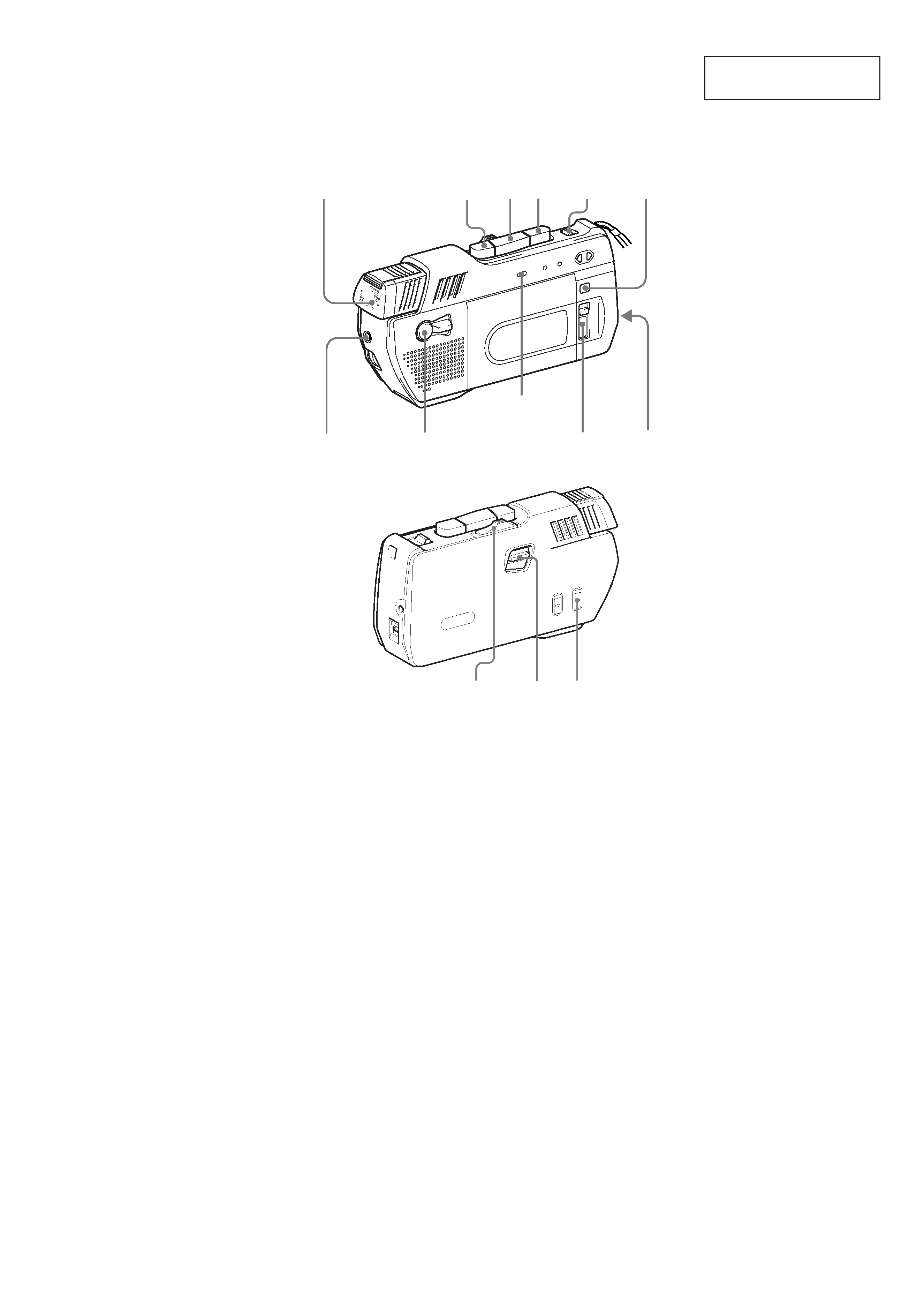
SECTION 1
GENERAL
Microphone
Micrófono
Microphone
z
xt
EAR
MIC MODE
TAPE
COUNTER
TAPE
SPEED
CUE
MARKER
REC lamp
Lámpara REC
Voyant
d'enregistrement
(REC)
DIR
nN
nN
VOR
PAUSE
FF/CUE·
REW/REVIEW
This section is extracted
from instruction manual.
4
M-200MC
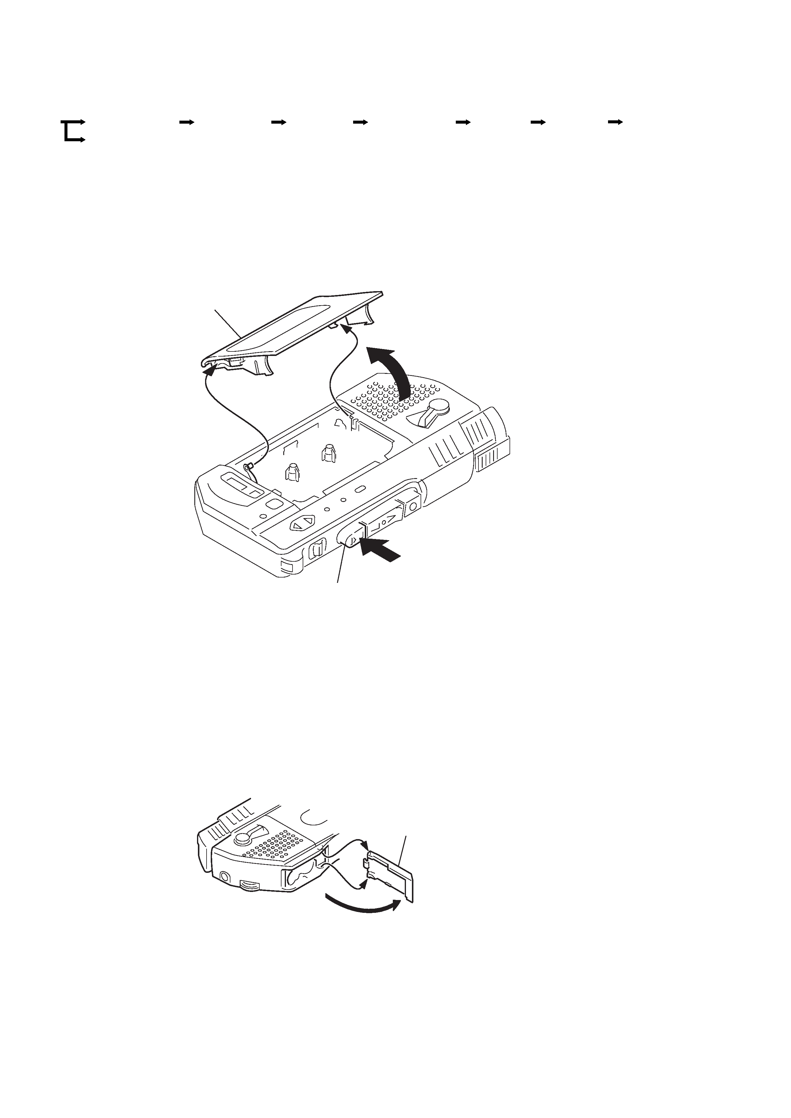
SECTION 2
DISASSEMBLY
· The equipment can be removed using the following procedure.
Note : Follow the disassembly procedure in the numerical order given.
2-1. LID ASSY, CASSETTE
Set
Lid assy, cassette
Head, ceramic
(HRPE901,902)
Lid assy,
battery case
Cabinet (rear)
assy
Microphone,
built-in C-2038 set
Main board
Mechanism
deck
Speaker,
LED board
2-2. LID ASSY, BATTERY CASE
2
3
4
1
Lid assy, cassette
Tx
(Eject/Stop) button
1
2
3
Lid assy, Battery case
5
M-200MC
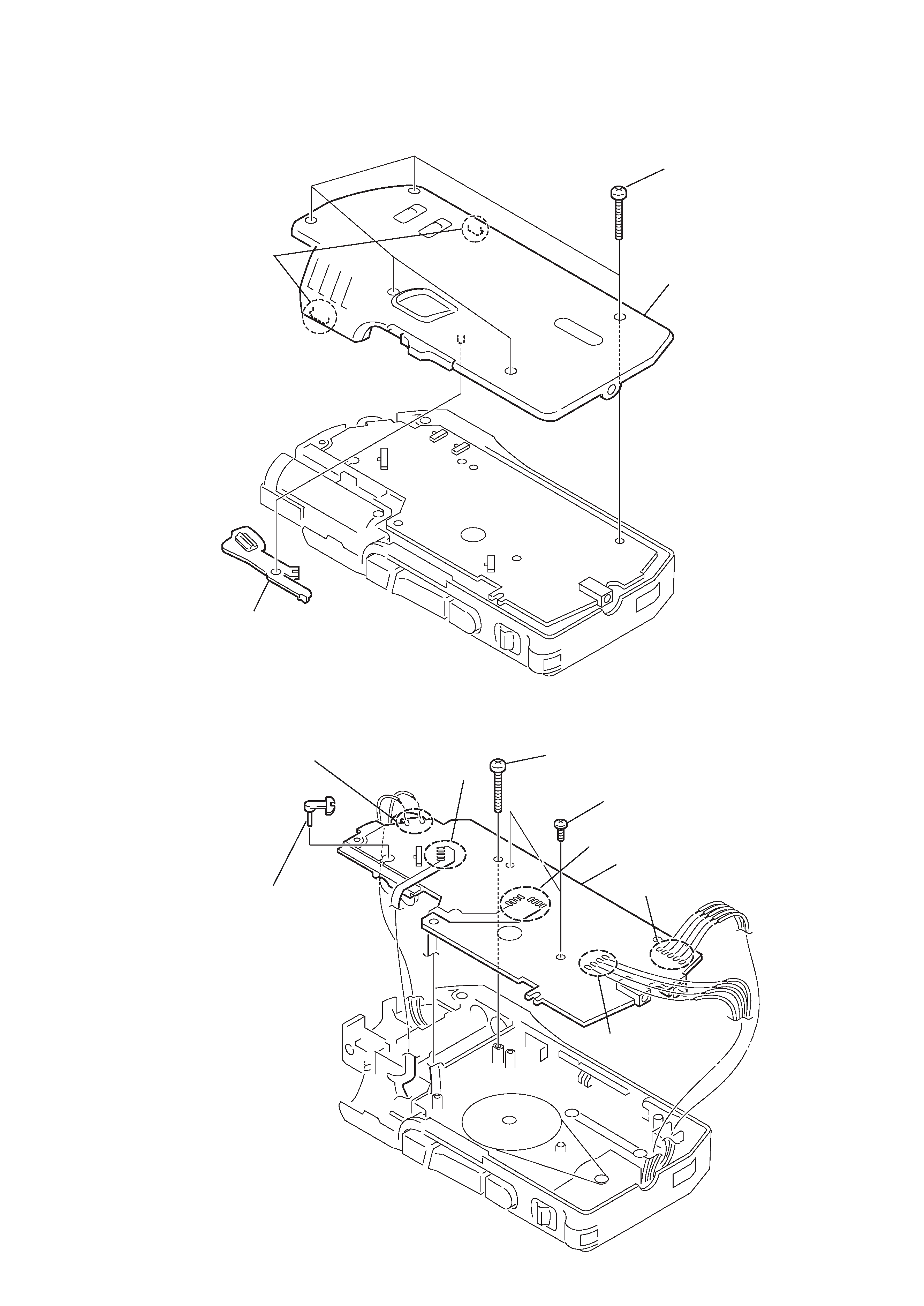
2-3. CABINET (REAR) ASSY
Note : When installing, fit the knobs and switches.
1
Five screws
(1.7
× 16)
3
Cabinet
(rear) assy
2
Claws
4
Knob (PAUSE)
2-4. MAIN BOARD
2
Unsolder the 2 places.
1
Lever (M SW), selection
3
Unsolder the 5 places.
4
Unsolder the 8 places.
5
Unsolder the 4 places.
6
Unsolder the 5 places.
7
Screw (1.7
× 16)
8
Two screws (M1.4
× 4.5)
9
Main board