SERVICE MANUAL
FM/AM PLL SYNTHESIZED RADIO
US Model
Canadian Model
SPECIFICATIONS
ICF-M88B
Ver 1.0 2004.05
9-877-839-01
2004E05-1
© 2004.05
Sony Corporation
Personal Audio Company
Published by Sony Engineering Corporation
Battery Life (Approx. hours)
(JEITA*)
When using
FM
AM
Sony alkaline size AA (LR6)
66
84
Sony size AA (R6)
23
31
*Measured by JEITA (Japan Electronics and Information Technology Industries
Association) standards.
The actual battery life may vary depending on circumstances of use.
Time display: 12-hour system
Frequency range:
Band
Range
Channel step
FM
87.5 - 108 MHz
0.1 MHz
AM
530 - 1 710 kHz
10 kHz
531 - 1 710 kHz
9 kHz
Speaker: Approx. 50 mm (2 inches) dia, 8
Power output: 80 mW (at 10% harmonic distortion)
Power requirements: 3V DC, two size AA (R6) batteries
Dimensions :
Approx. 166.8
× 70 × 95 mm (w/h/d) (6 5/
8 × 2
7/
8 × 3
3/
4 inches) incl.
projecting parts and control.
Mass: Approx. 281.4 g (9.93 oz) incl. batteries / excl. accessories
Supplied accessories:
Mount with wheel sensor (1), Thick/Thin rubber pads (2 each),
Wheel magnet (1), Zip ties (5), Double-sided tape (1), Screws (2)
Design and specifications are subject to change without notice.

2
ICF-M88B
TABLE OF CONTENTS
1.
SERVICING NOTES ............................................... 2
2.
GENERAL ................................................................... 3
3.
DISASSEMBLY
3-1.
Disassembly Flow ...........................................................
4
3-2.
Cabinet (Lower) Block ....................................................
4
3-3.
Chassis Assy ....................................................................
5
3-4.
MAIN Board ....................................................................
5
4.
TEST MODE .............................................................. 7
5.
ELECTRICAL ADJUSTMENTS ......................... 8
6.
DIAGRAMS
6-1.
Printed Wiring Boards TUNER Section ................... 10
6-2.
Schematic Diagram TUNER Section ....................... 11
6-3.
Printed Wiring Board
PANEL/POWER SUPPLY Section ........................... 12
6-4.
Schematic Diagram
PANEL/POWER SUPPLY Section ........................... 13
7.
EXPLODED VIEWS
7-1.
Cabinet (Upper) Section .................................................. 16
7-2.
Chassis Section ................................................................ 17
7-3.
Cabinet (Lower) Section .................................................. 18
8.
ELECTRICAL PARTS LIST ................................ 19
Notes on chip component replacement
· Never reuse a disconnected chip component.
· Notice that the minus side of a tantalum capacitor may be
damaged by heat.
SECTION 1
SERVICING NOTES
UNLEADED SOLDER
Boards requiring use of unleaded solder are printed with the lead-
free mark (LF) indicating the solder contains no lead.
(Caution: Some printed circuit boards may not come printed with
the lead free mark due to their particular size)
: LEAD FREE MARK
Unleaded solder has the following characteristics.
· Unleaded solder melts at a temperature about 40 °C higher
than ordinary solder.
Ordinary soldering irons can be used but the iron tip has to be
applied to the solder joint for a slightly longer time.
Soldering irons using a temperature regulator should be set to
about 350 °C.
Caution: The printed pattern (copper foil) may peel away if
the heated tip is applied for too long, so be careful!
· Strong viscosity
Unleaded solder is more viscou-s (sticky, less prone to flow)
than ordinary solder so use caution not to let solder bridges
occur such as on IC pins, etc.
· Usable with ordinary solder
It is best to use only unleaded solder but unleaded solder may
also be added to ordinary solder.
3
ICF-M88B
SECTION 2
GENERAL
This section is extracted from
instruction manual.
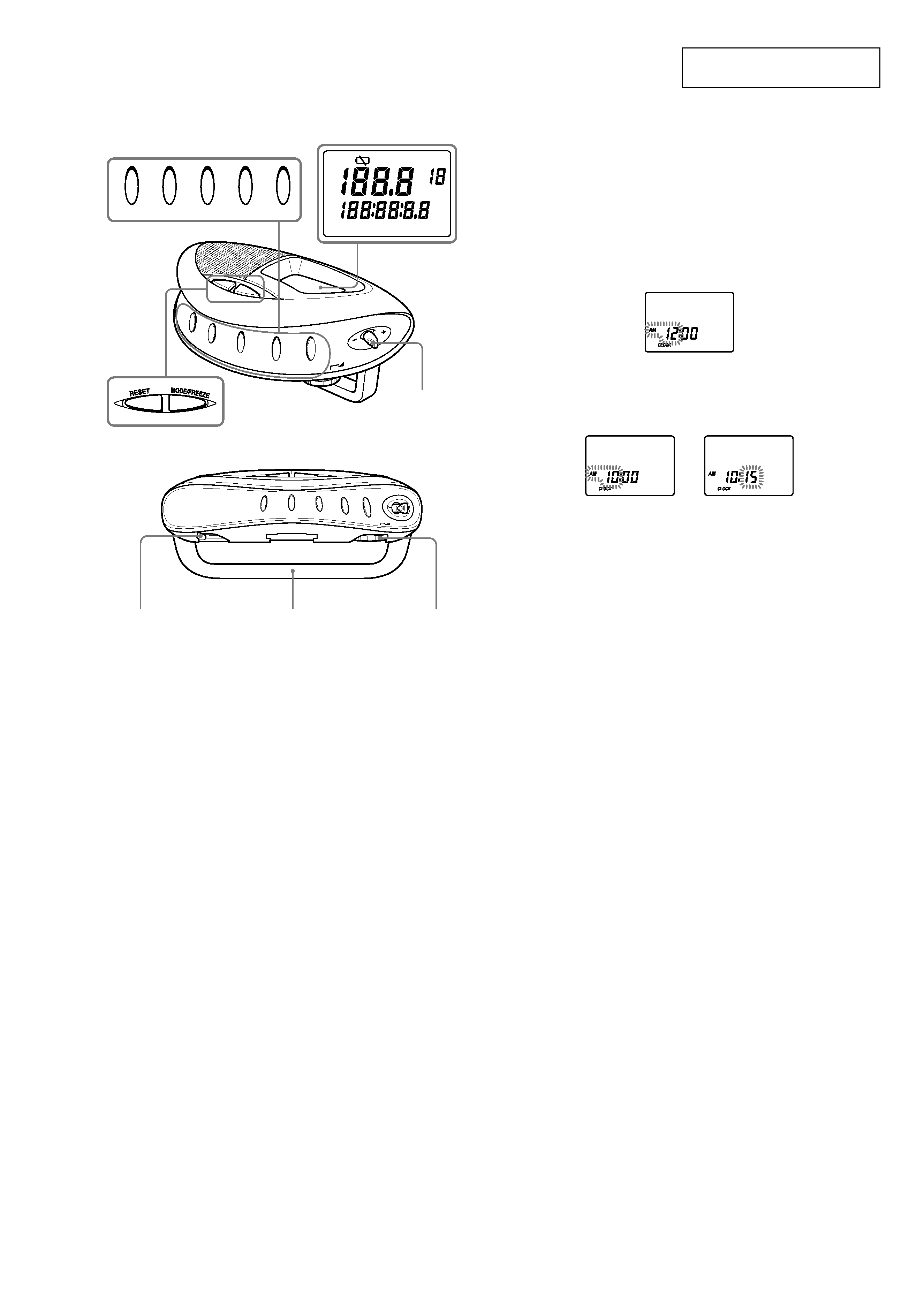
Location of Controls
RADIO POWER
LIGHT
ENTER/SELECT
TUNE MODE
BAND/SET
VOL
BAND/SET
TUNE MODE
RADI
OPO
WER
LIGH
T
VOL
ENTER
/SELECT
MPH
AM
PM
FM
FREEZE
PRESET
MHz
MP H
kHz
km /h in ch
AM
km /h
m ile
CLOCK ODO DIST RT AVG MAX
mm
RADIO POWER
LIGHT
ENTER/SELECT TUNE MODE
BAND/SET
VOL*
FM a n te n n a
FM S ENS
DX/LOCAL
J og le ve r
*
Th e re is a tactile dot bes ide VOL to s how th e direction to tu rn up
th e vo lume .
Setting the Clock
The clock time display of this unit is a 12-hour system.
When the batteries are first installed, AM 12:00 flashes and CLOCK turns on
in the display.
1 Press RADIO POWER to turn off the power.
2 Press MODE/FREEZE repeatedly until CLOCK appears.
3 Hold down ENTER/SELECT for more than 2 seconds until
AM 12 starts flashing.
4 Push the Jog lever towards + or to adjust the hour, then press
ENTER/SELECT.
The beep sounds and the minute setting starts to flash.
If you hold down the Jog lever towards
+ or --, the digit changes rapidly.
Midnight is indicated as AM 12:00 and Noon is indicated by PM 12:00.
g
5 Repeat step 4 above to adjust the minutes.
: starts flashing and the clock starts operating.
To set the current time exactly to the second, adjust the minute setting and
then press
ENTER/S ELECT to synchronize it with a time signal (such as
the telephone time signal).
No te
If you do not push the Jog lever towards
+ or --, or ENTER/S ELECT within
about 65 seconds, the clock setting mode will be canceled.
ICF-M88B
4
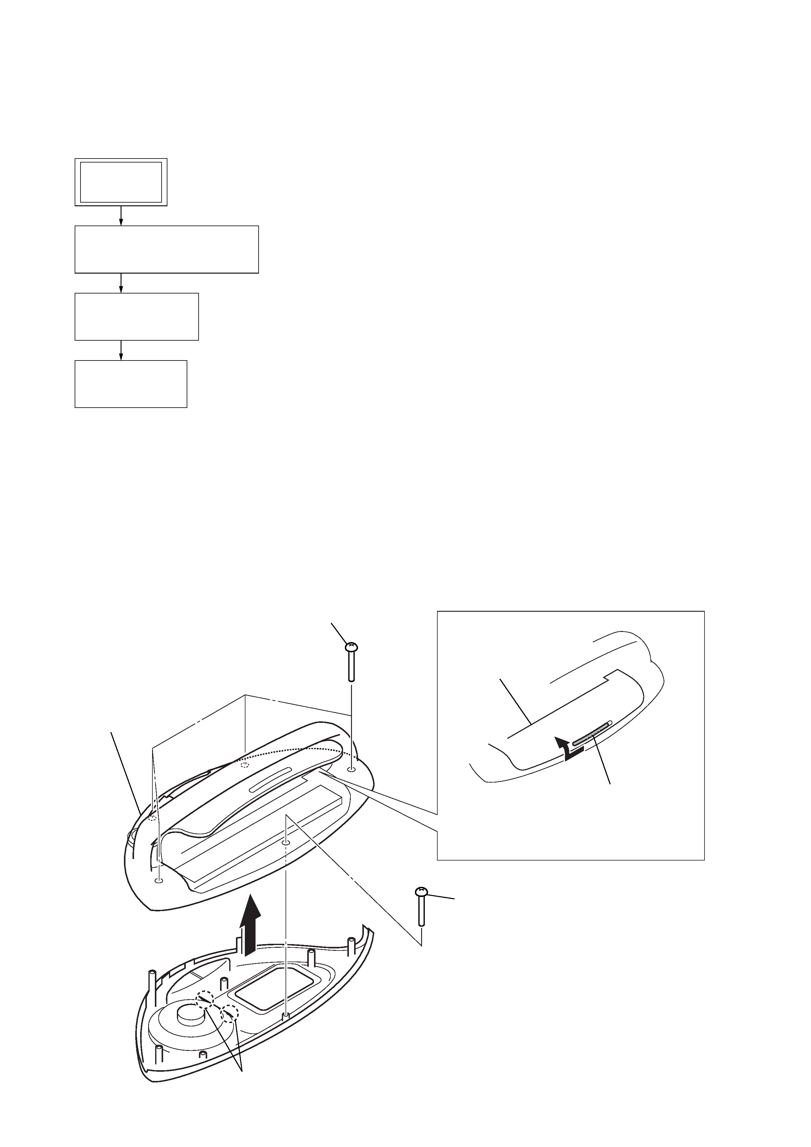
· This set can be disassembled in the order shown below.
3-1. DISASSEMBLY FLOW
SECTION 3
DISASSEMBLY
Note: Follow the disassembly procedure in the numerical order given.
3-2. CABINET (LOWER) BLOCK
1
Slide the hook (battery case lid)
in the direction of arrow,
and open the battery case lid.
battery case lid
2
screw (P1.7
× 10)
4
5
Remove two solders.
3
four screws
(P1.7
× 10)
6
cabinet (lower) block
3-2. CABINET (LOWER) BLOCK
(Page 4)
3-3. CHASSIS ASSY
(Page 5)
3-4. MAIN BOARD
(Page 5)
SET
ICF-M88B
5
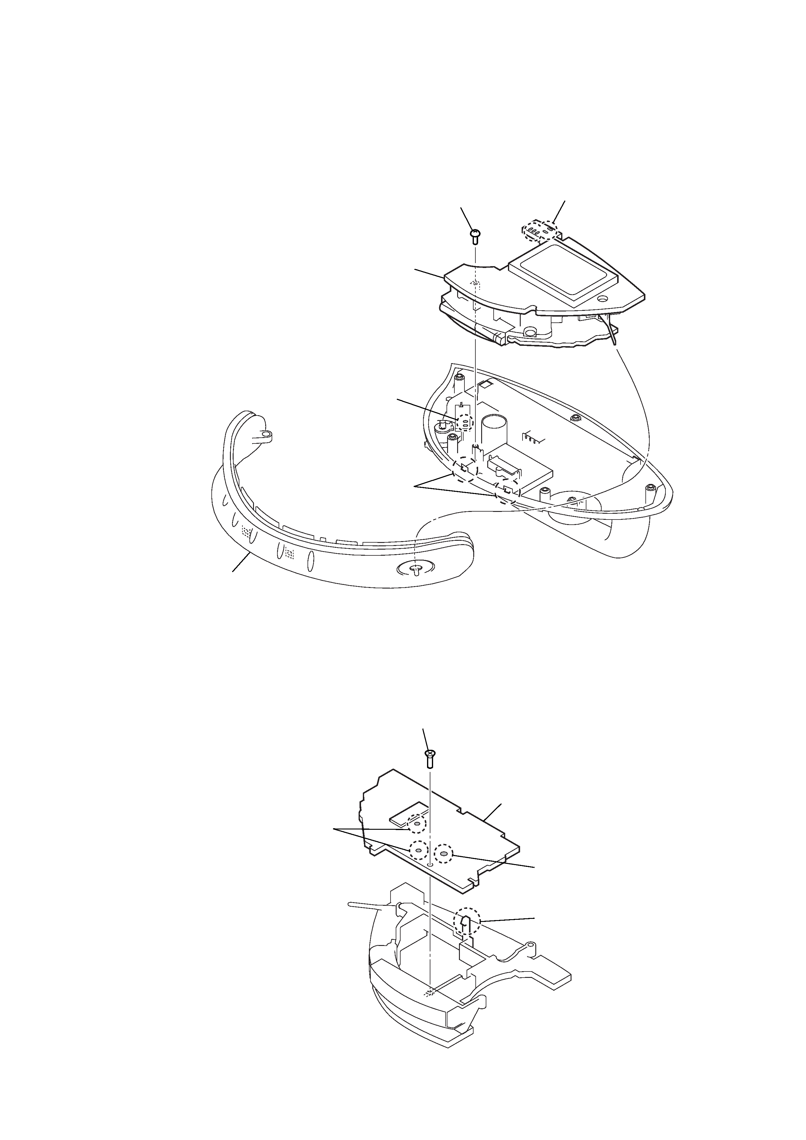
3-4. MAIN BOARD
3-3. CHASSIS ASSY
1
Remove five solders.
4
screw
5
chassis assy
3
button assy
1
Remove two solders.
2
two hooks
3
screw
4
MAIN board
1
Remove the solder.
1
Remove two solders.
2
hook