ECM-T115/T145
US Model
Canadian Model
AEP Model
E Model
SERVICE MANUAL
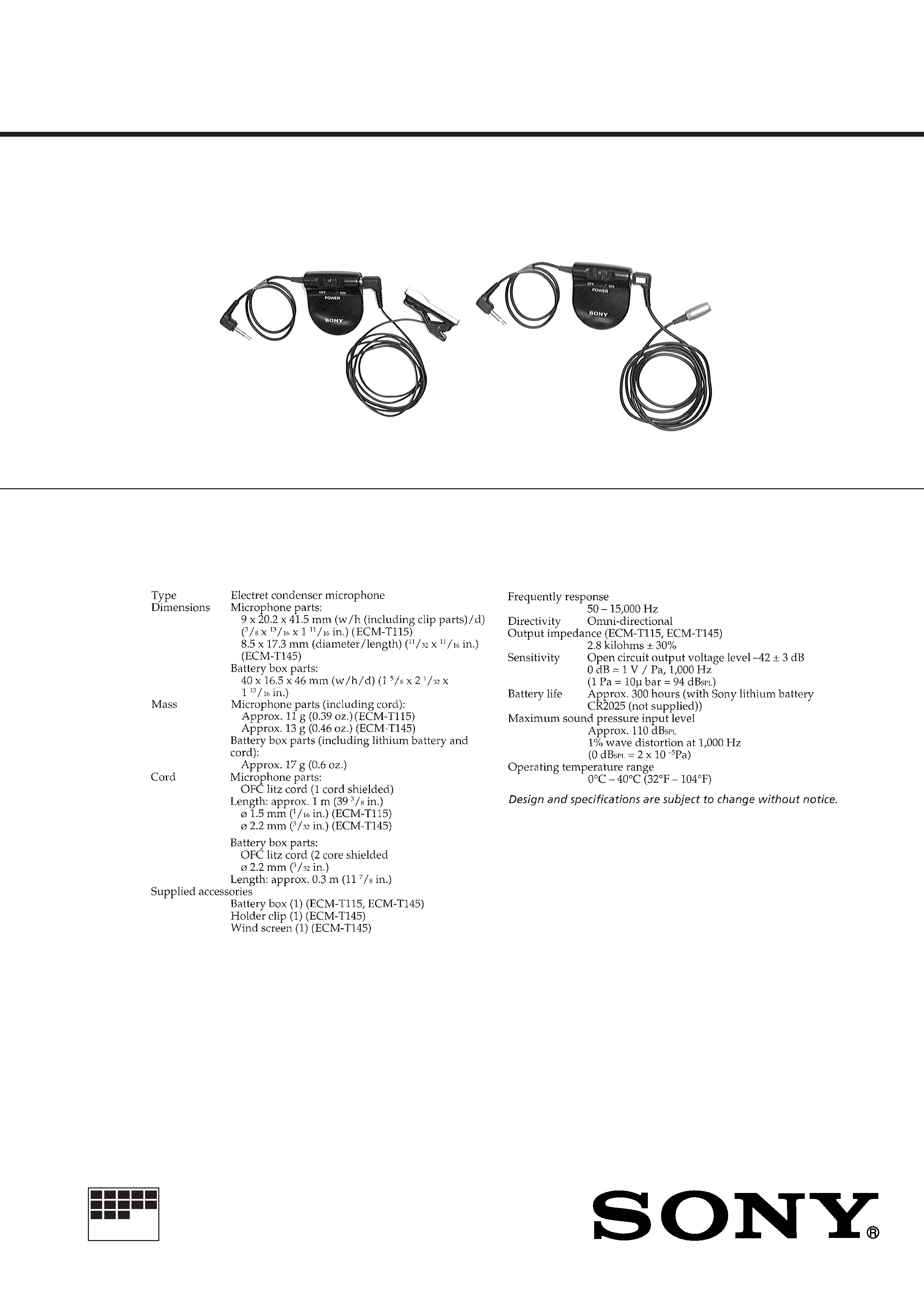
ELECTRET CONDENSER MICROPHONE
MICROFILM
SPECIFICATIONS
PHOTO : ECM-T115
PHOTO : ECM-T145
Ver 1.0 1999. 02
-- 2 --
Notes on Chip Component Replacement
· Never reuse a disconnected chip component.
· Notice that the minus side of a tantalum capacitor may be
damaged by heat
SERVICE NOTE
-- 3 --
SECTION 1
GENERAL
This section is extracted
from instruction manual.
-- 4 --
SECTION 2
DIAGRAMS
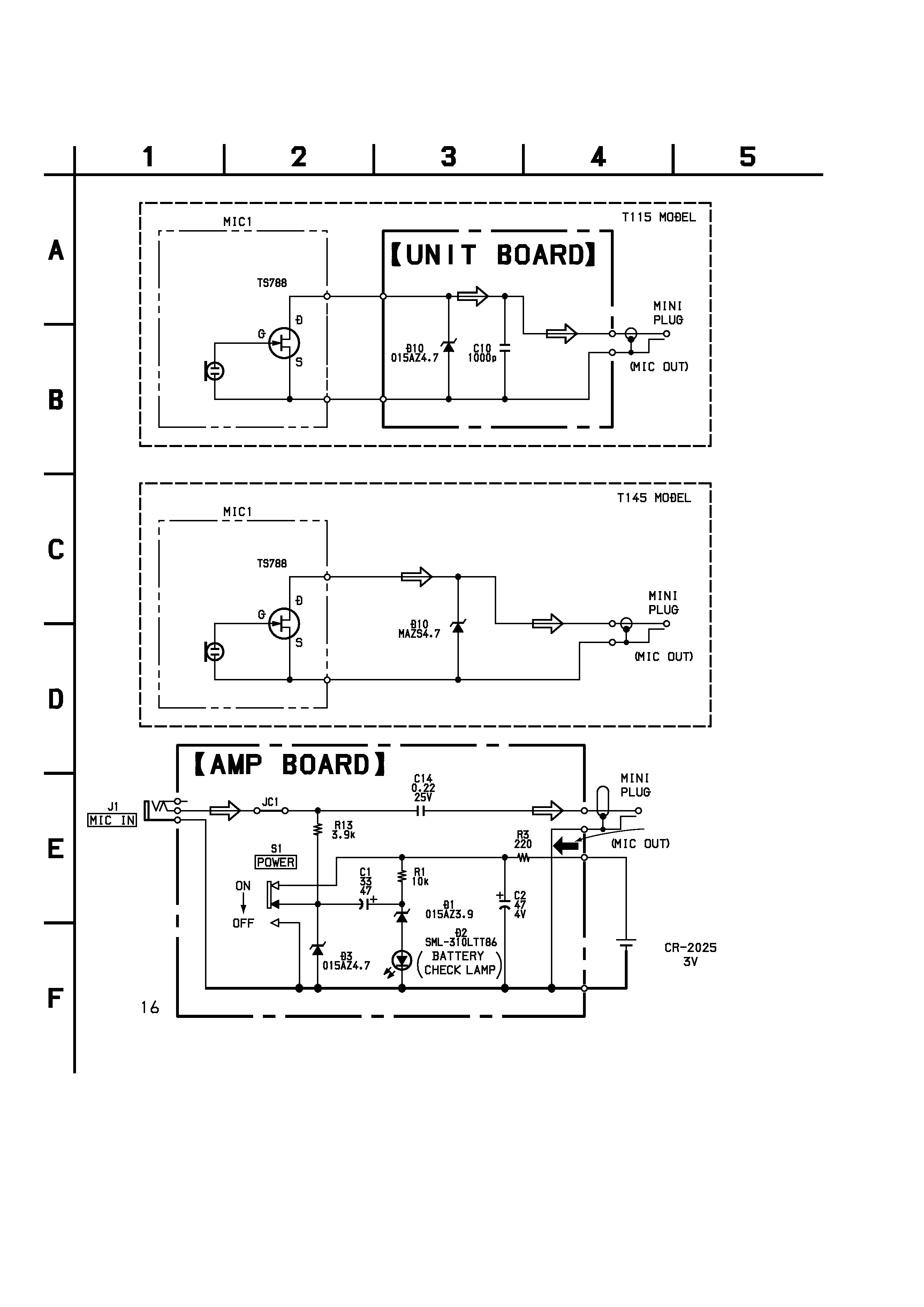
2-1. SCHEMATIC DIAGRAM
TOTAL CURRENT : 0.21mA
LITHIUM BATTERY
Note on Schematic Diagram:
· All capacitors are in µF unless otherwise noted. pF: µµF
50 WV or less are not indicated except for electrolytics
and tantalums.
· All resistors are in
and 1/4 W or less unless otherwise
specified.
·
%
: indicates tolerance.
· C : panel designation.
· Signal path.
F
: MIC
ECM-T115/T145
-- 5 --
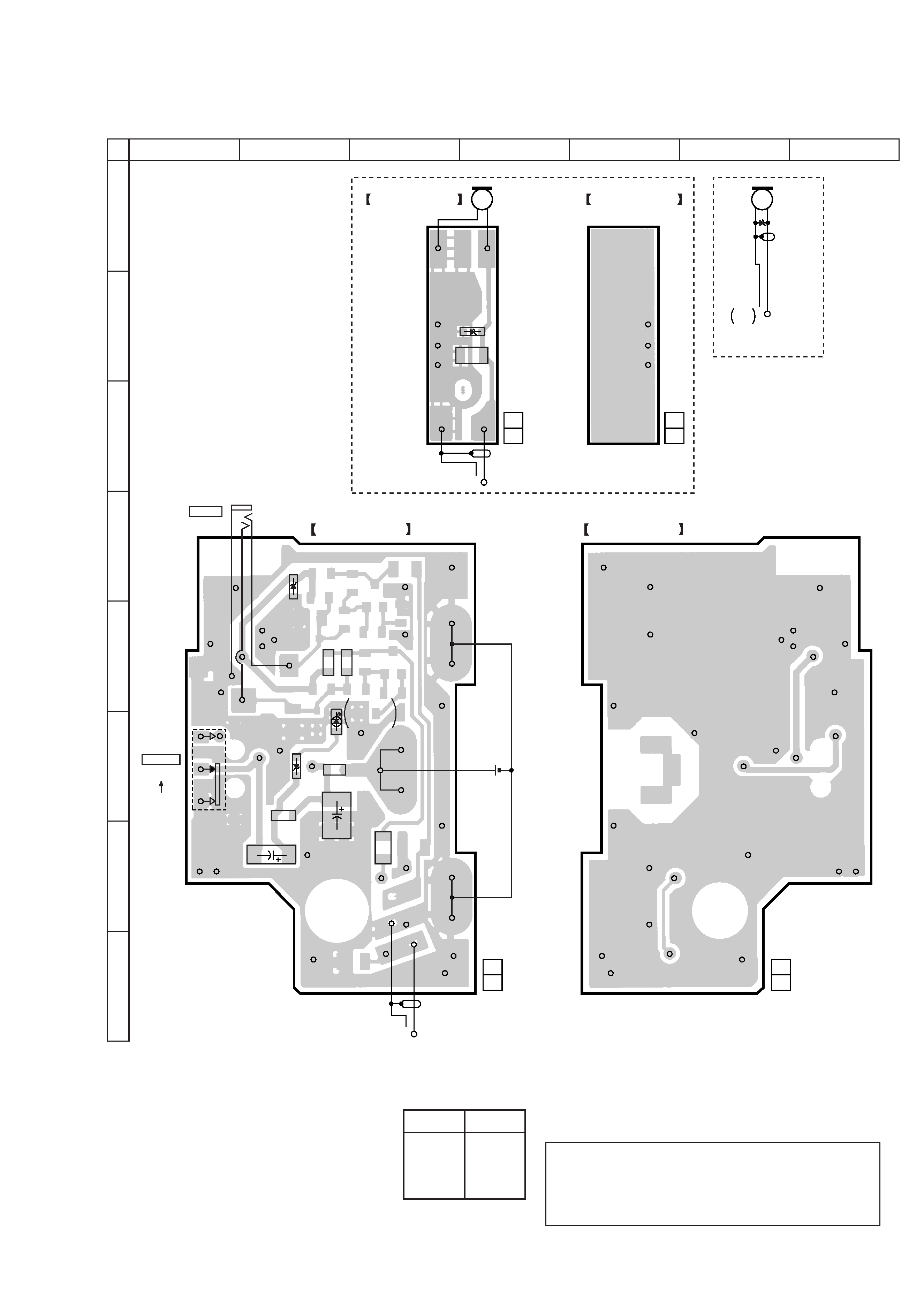
2-2. PRINTED WIRING BOARD
12
A
B
C
D
E
F
G
H
34567
AMP BOARD (SIDE B)
UNIT BOARD
(SIDE B)
UNIT BOARD
(SIDE A)
AMP BOARD (SIDE A)
1-671-999-
11
(11)
1-671-999-
11
(11)
1-672-000-
11
(11)
1-672-000-
11
(11)
J1
MIC IN
S1
POWER
D10
D10
D3
R13
JC1
D1
C14
C1
C2
R1
D2
C10
R3
ON
OFF
S1
(MIC OUT)
MINI
PLUG
(MIC OUT)
MIC1
MINI
PLUG
MIC
OUT
MINI
PLUG
MIC1
LITHUM
BATTERY
CR-2025
3V
T145 MODEL
T115 MODEL
BATTERY
CHECK
LAMP
16
Note on Printed Wiring Board:
· X : parts extracted from the component side.
·
®
: Through hole.
· b : Pattern from the side which enables seeing.
Caution:
Pattern face side:
Parts on the pattern face side seen from
(SIDE B)
the pattern face are indicated.
Parts face side:
Parts on the parts face side seen from
(SIDE A)
the parts face are indicated.
Ref. No.
Location
D1
F-2
D2
F-2
D3
D-2
D10
B-4, A-6
· Semiconductor
Location
ECM-T115/T145