MICROFILM
SERVICE MANUAL
AEP Model
Hong Kong Model
UK Model
CD/DVD PLAYER
DVP-S7700
RMT-D107E/D107P
SPECIFICATIONS
2
SAFETY CHECK-OUT
WARNING!!
WHEN SERVICING, DO NOT APPROACH THE LASER
EXIT WITH THE EYE TOO CLOSELY. IN CASE IT IS
NECESSARY TO CONFIRM LASER BEAM EMISSION,
BE SURE TO OBSERVE FROM A DISTANCE OF
MORE THAN 25 cm FROM THE SURFACE OF THE
OBJECTIVE LENS ON THE OPTICAL PICK-UP BLOCK.
CAUTION:
The use of optical instrument with this product will increase eye
hazard.
CAUTION
Use of controls or adjustments or performance of procedures
other than those specified herein may result in hazardous ra-
diation exposure.
SAFETY-RELATED COMPONENT WARNING!!
COMPONENTS IDENTIFIED BY MARK
! OR DOTTED
LINE WITH MARK
! ON THE SCHEMATIC DIAGRAMS
AND IN THE PARTS LIST ARE CRITICAL TO SAFE
OPERATION. REPLACE THESE COMPONENTS WITH
SONY PARTS WHOSE PART NUMBERS APPEAR AS
SHOWN IN THIS MANUAL OR IN SUPPLEMENTS PUB-
LISHED BY SONY.
1. Check the area of your repair for unsoldered or poorly-sol-
dered connections. Check the entire board surface for solder
splashes and bridges.
2. Check the interboard wiring to ensure that no wires are
"pinched" or contact high-wattage resistors.
3. Look for unauthorized replacement parts, particularly transis-
tors, that were installed during a previous repair. Point them
out to the customer and recommend their replacement.
SAFETY CHECK-OUT
After correcting the original service problem, perform the following
safety checks before releasing the set to the customer:
4. Look for parts which, though functioning, show obvious signs
of deterioration. Point them out to the customer and recom-
mend their replacement.
5. Check the B+ voltage to see it is at the values specified.
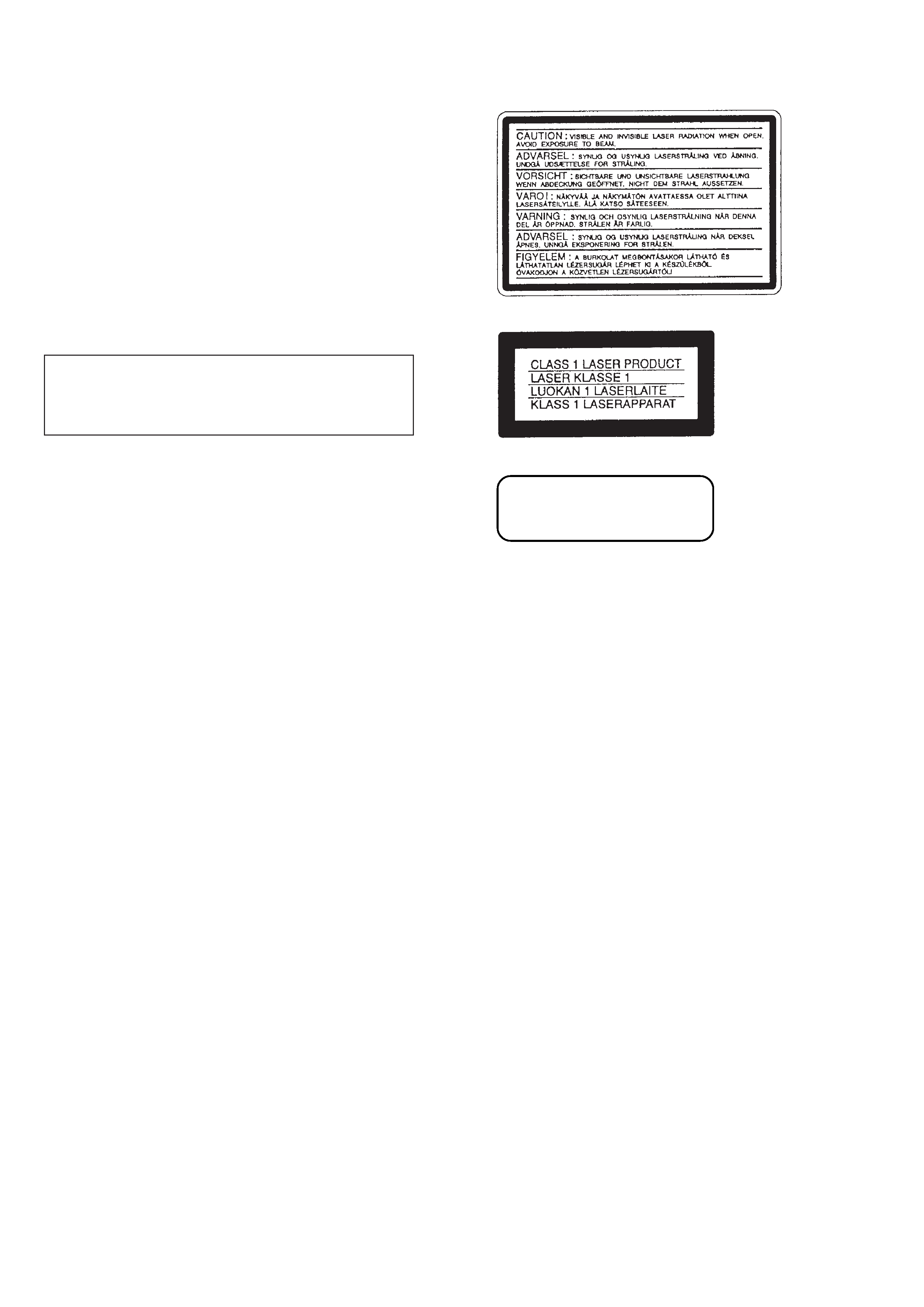
CLASS 3B LASER
LUOKAN 3B LASER
LASERKLASS 3B

3
TABLE OF CONTENTS
Section
Title
Page
Section
Title
Page
Service Note ............................................................................ 4
1.
GENERAL
This Player Can Play the Following Discs .................... 1-1
Getting Started .............................................................. 1-1
Basic Operations ........................................................... 1-2
Playing Discs in Various Modes .................................... 1-4
Setting and Adjustments ............................................... 1-9
Additional Information ................................................... 1-10
2.
DISASSEMBLY
2-1.
Upper Case Removal .................................................... 2-1
2-2.
Front Panel Removal .................................................... 2-1
2-3.
Door Open/Close Motor Removal ................................. 2-1
2-4.
MB-84 Board Removal .................................................. 2-1
2-5.
AU-218 Board Removal ................................................ 2-2
2-6.
MD Block Ass'y Removal .............................................. 2-2
2-7.
TK-47 Board Removal ................................................... 2-2
2-8.
Tray Removal ................................................................ 2-2
2-9.
Skew Motor (M903) Removal ....................................... 2-3
2-10. Sled Motor (M501) Removal ......................................... 2-3
2-11. Spindle Motor (M901) Removal .................................... 2-3
2-12. Optical Pick-up Removal ............................................... 2-3
2-13. Internal Views ................................................................ 2-4
2-14. Circuit Boards Location ................................................. 2-5
3.
BLOCK DIAGRAMS
3-1.
Overall Block Diagram .................................................. 3-1
3-2.
RF/Servo Block Diagram .............................................. 3-3
3-3.
Signal Process Block Diagram ..................................... 3-5
3-4.
Video Block Diagram ..................................................... 3-7
3-5.
System Control Block Diagram ..................................... 3-9
3-6.
Audio Block Diagram ..................................................... 3-11
3-7.
Mode Control Block Diagram ........................................ 3-13
3-8.
Power Block Diagram .................................................... 3-15
4.
PRINTED WIRING BOARDS AND SCHEMATIC
DIAGRAMS
4-1.
Frame Schematic Diagram ........................................... 4-3
4-2.
Printed Wiring Boards and Schematic Diagrams ......... 4-7
TK-47 Printed Wiring Board .......................................... 4-7
TK-47 (RF, Servo 1) Schematic Diagram ..................... 4-11
TK-47 (RF, Servo 2) Schematic Diagram ..................... 4-13
MB-84, FG-43 Printed Wiring Boards ........................... 4-15
MB-84 (AV Decoder) Schematic Diagram .................... 4-19
MB-84 (Clock Generator) Schematic Diagram ............. 4-21
MB-84 (DNR) Schematic Diagram ................................ 4-23
MB-84 (Video Encoder) Schematic Diagram ................ 4-25
MB-84 (Drive 1) Schematic Diagram ............................ 4-27
MB-84 (Drive 2), FG-43 Schematic Diagrams .............. 4-29
MB-84 (DSP 1) Schematic Diagram ............................. 4-31
MB-84 (DSP 2) Schematic Diagram ............................. 4-33
MB-84 (Bias) Schematic Diagram ................................ 4-35
MB-84 (IF µ-com) Schematic Diagram ......................... 4-37
MB-84 (L Gate Array) Schematic Diagram ................... 4-39
MB-84 (ARP, Decrypt) Schematic Diagram .................. 4-41
MB-84 (System µ-com) Schematic Diagram ................ 4-43
MB-84 (S Gate Array) Schematic Diagram .................. 4-45
AU-218 Printed Wiring Board ....................................... 4-47
AU-218 (Audio 1) Schematic Diagram ......................... 4-51
AU-218 (Audio 2) Schematic Diagram ......................... 4-53
AU-218 (Video Buffer) Schematic Diagram .................. 4-55
YS-19 Printed Wiring Board and
Schematic Diagram ....................................................... 4-57
ER-8 Printed Wiring Board ............................................ 4-59
ER-8 (EURO AV 1) Schematic Diagram ....................... 4-63
ER-8 (EURO AV 2) Schematic Diagram ....................... 4-65
ER-8 (EURO AV 3) Schematic Diagram ....................... 4-67
HP-120 Printed Wiring Board and
Schematic Diagram ....................................................... 4-69
FP-75 Printed Wiring Board .......................................... 4-71
FP-75 Schematic Diagram ............................................ 4-73
CN-113, DR-88, FL-108, FR-160, PW-120
Printed Wiring Boards ................................................... 4-75
CN-113, DR-88, FL-108, FR-160, PW-120
Schematic Diagrams ..................................................... 4-77
PS-421 Printed Wiring Board ........................................ 4-79
PS-421 Schematic Diagram .......................................... 4-81
POWER BLOCK (HS-930SH) Printed Wiring Board .... 4-83
POWER BLOCK (HS-930SH) Schematic Diagram ...... 4-85
5.
IC PIN FUNCTION DESCRIPTION
5-1.
Interface Control Pin Function (MB-84 Board IC604) .. 5-1
5-2
System Control Pin Function (MB-84 Board IC805) .... 5-2
6.
TEST MODE
6-1.
Starting up Test Mode ................................................... 6-1
6-2.
Selection of Check Item ................................................ 6-1
6-2-1. Selected Item Check ................................................ 6-1
6-2-2. All Items Check ........................................................ 6-1
6-3.
Error Display .................................................................. 6-2
6-4.
General Description of Checking Method ..................... 6-2
6-5.
Drive Auto Adjustment .................................................. 6-8
6-6.
Drive Manual Operation ................................................ 6-12
6-6-1. Drive Manual Operation Menu Screen .................... 6-12
6-6-2. Disc Type .................................................................. 6-12
6-6-3. Manual Control 1 ...................................................... 6-12
6-6-4. Manual Control 2 ...................................................... 6-13
6-6-5. Manual Control 3 ...................................................... 6-13
6-6-6. Manual Adjust 1 ....................................................... 6-13
6-6-7. Manual Adjust 2 ....................................................... 6-14
6-6-8. Auto Adjust ............................................................... 6-14
6-6-9. Check ....................................................................... 6-14
6-6-10. EEPROM Data Screen Display ................................ 6-15
6-7.
Other Operation ............................................................. 6-15
6-8.
Emergency History ........................................................ 6-16
6-9.
Error Code ..................................................................... 6-18
7.
ELECTRICAL ADJUSTMENT
7-1.
Power Supply Check ..................................................... 7-1
1.
HS-930SH Board ........................................................... 7-1
7-2.
Adjustment of System Control ...................................... 7-2
1.
System Clock 27 MHz Adjustment ................................ 7-2
7-3.
Adjustment of Video System ......................................... 7-2
1.
Video Level Adjustment ................................................ 7-2
2.
S-terminal Output Check ............................................... 7-2
3.
Checking Component Video Output B-Y ...................... 7-2
4.
Checking Component Video Output R-Y ...................... 7-3
5.
Checking Component Video Output Y .......................... 7-3
6.
Checking RGB Output R ............................................... 7-3
7.
Checking RGB Output G ............................................... 7-3
8.
Checking RGB Output B ............................................... 7-4
9.
Checking S Video Output S-C ...................................... 7-4
10. Checking S Video Output DC Level .............................. 7-4
7-4.
Adjustment Related Parts Arrangement ....................... 7-6
8.
REPAIR PARTS LIST
8-1.
Exploded Views ............................................................. 8-1
8-1-1. Case Assembly ........................................................ 8-1
8-1-2. Front Panel Assembly .............................................. 8-2
8-1-3. Chassis Assembly .................................................... 8-3
8-1-4. DVD Mechanism Chassis Assembly (1) .................. 8-5
8-1-5. DVD Mechanism Chassis Assembly (2) .................. 8-6
8-2.
Electrical Parts List ........................................................ 8-7
4
SERVICE NOTE
1.
DISASSEMBLY
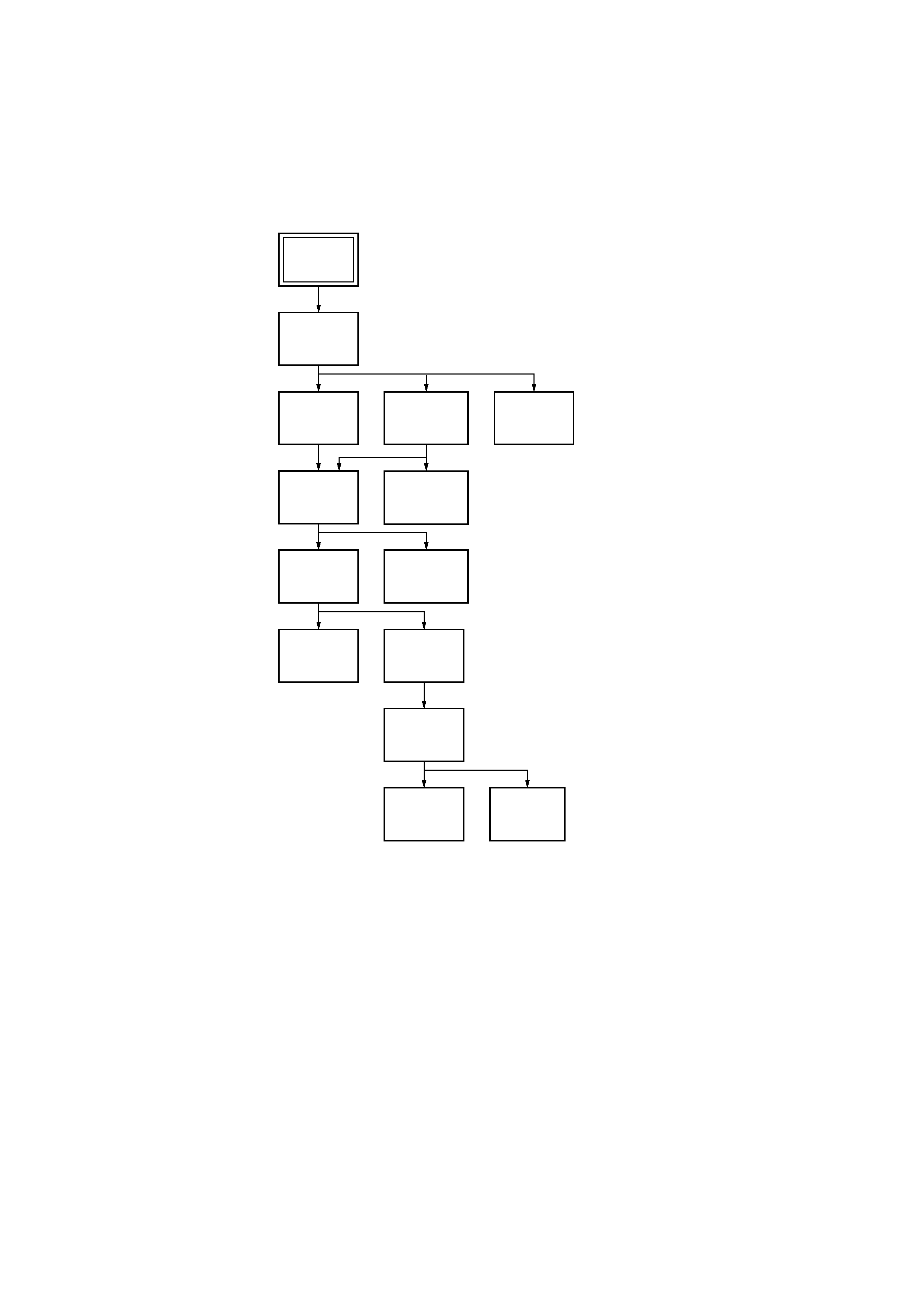
· This set can be disassembled in the order shown below.
Tray
(Page 2-2)
TK-47
Board
(Page 2-2)
Upper Case
(Page 2-1)
MB-84
Board
(Page 2-1)
Front Panel
Section
(Page 2-1)
Door Open/
Close Motor
(Page 2-1)
AU-218
Board
(Page 2-2)
MD Block
Ass'y
(Page 2-2)
Optical
Pick-up
(Page 2-3)
Skew
Motor
(Page 2-3)
Spindle
Base
(Page 2-3)
Sled
Motor
(Page 2-3)
Spindle
Motor
(Page 2-3)
Set
5
2.
DISK REMOVAL PROCEDURE
(at POWER OFF)
2-1.
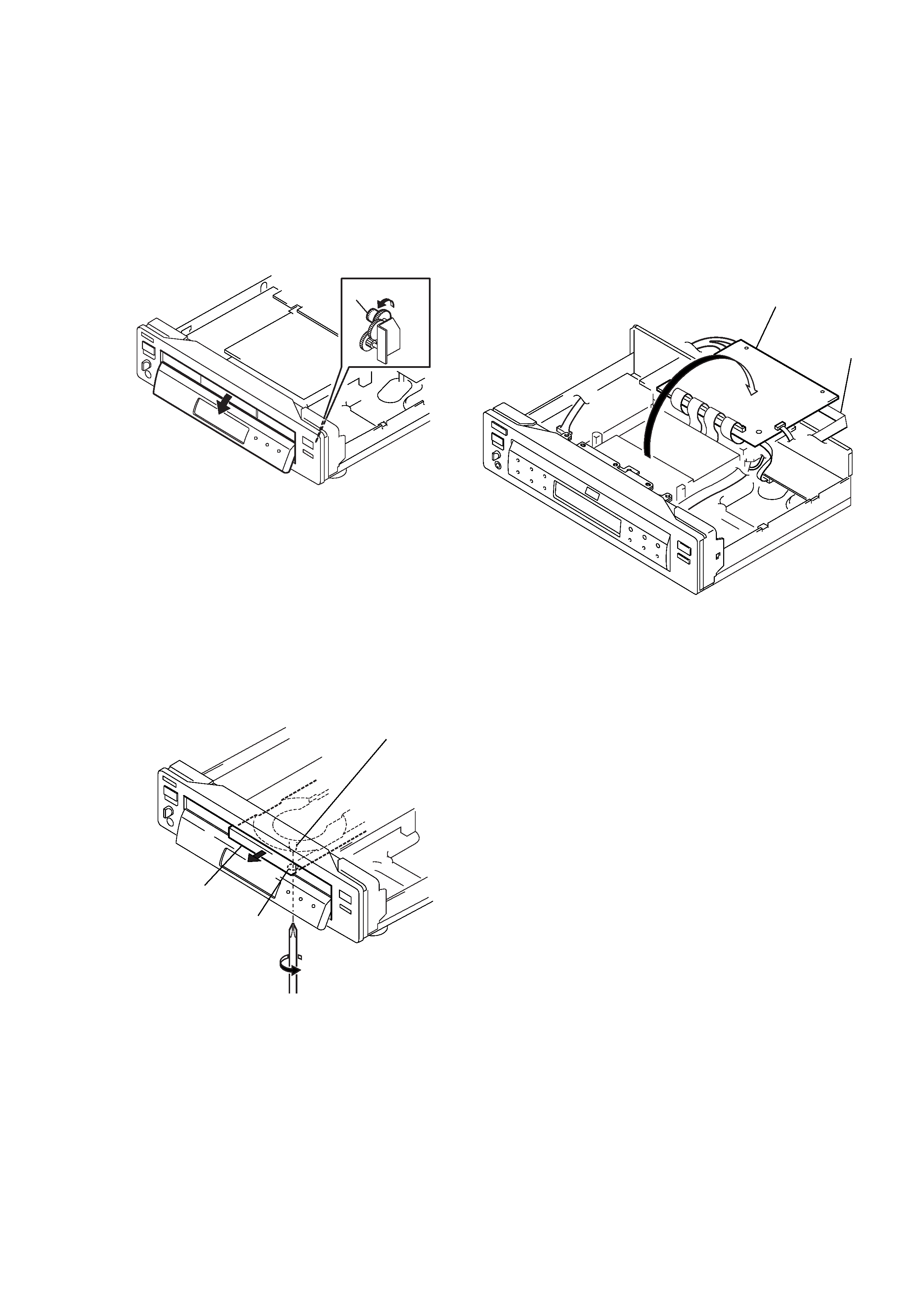
How to Open the Door
1) With the top case removed, rotate the gear (D) 1 in direction
A to open the door. (See Fig. 1)
Fig. 1
2-2. How to Draw out Tray
1) Insert a cross-tip screwdriver into a hole at the bottom, and
rotate the cam gear 2 in direction B. (See Fig. 2)
Note: To prevent a damage of cam gear, rotate it in direction
B by 1/4 turn.
2) Draw out the tray 3 in direction C by hand, and remove a
disk. (See Fig. 2)
Fig. 2
1 Gear (D)
A
B
C
2 Cam gear
3 Tray
Hole
3.
HOW TO SERVICE MB-84 (SIDE B) BOARD
1) Remove the case from the set. (Refer to 2-1)
2) Remove the cover (upper). (Refer to 2-3)
3) Set the MB-84 board as shown in Fig. 3.
Note 1: Do not disconnect wiring.
Note 2: Spread a insulating material under the MB-84 board
and through down lest you should short.
4) Mount the extention cable (J-6090-079-A).
(MB-84 (CN601)
FL-107 (CN153))
Fig. 3
MB-84 board
Extention Cable
(J-6090-079-A)