3-858-189-12(1)
3-858-189-12(1)
Digital Audio
Tape Deck
DTC-ZE700
© 1996 by Sony Corporation
ES
P
F
EN
Operating Instructions
Mode d'emploi
Manual de instrucciones
Manual de Instruções
2
EN
3-858-189-11(1)
WARNING
To prevent fire or shock
hazard, do not expose the unit
to rain or moisture.
To avoid electrical shock, do
not open the cabinet. Refer
servicing to qualified
personnel only.
For the customers in the
United States
Welcome!
Thank you for purchasing the Sony
Digital Audio Tape Deck. Before
operating the unit, please read this
manual thoroughly and retain it for
future reference.
The DTC-ZE700 has the following
features:
· High-density linear converters
A pulse A/D converter that produces
clear, elegant sound quality and
theoretically zero cross distortion, and
a pulse D/A converter with a newly
developed digital filter and a full
feedforward format that reduces
quantizing noise in the audible
bandwidth, thus expanding the range
of spatial expression.
· SBM (Super Bit Mapping) function
(see page 21)
· The Serial Copy Management System
(see page 22)
· Three sampling frequencies (48 kHz,
44.1 kHz, 32 kHz)
· Recording and playback in long-play
mode.
· Analog recording at 44.1 kHz
· Sub codes
Start IDs, program numbers and other
sub codes written to the tape allow
you to locate tracks quickly.
· See-through cassette compartment lid
A see-through cassette compartment
lid that allows you to view tape
operations during playback and
recording.
About This Manual
The instructions in this manual are for
DTC-ZE700.
Conventions
Instructions in this manual describe the
controls on the deck.
The following icons are used in this
manual:
z
Indicates useful information or
tips that make a task easier.
Z
Indicates a task that requires use
of the remote.
INFORMATION
This equipment has been tested and
found to comply with the limits for a
Class B digital device, pursuant to
Part 15 of the FCC Rules.
These limits are designed to provide
reasonable protection against harmful
interference in a residential
installation. This equipment
generates, uses, and can radiate radio
frequency energy and, if not installed
and used in accordance with the
instructions, may cause harmful
interference to radio communications.
However, there is no guarantee that
interference will not occur in a
particular installation. If this
equipment does cause harmful
interference to radio or television
reception, which can be determined
by turning the equipment off and on,
the user is encouraged to try to
correct the interference by one or
more of the following measures:
-- Reorient or relocate the receiving
antenna.
-- Increase the separation between
the equipment and receiver.
-- Connect the equipment into an
outlet on a circuit different from
that to which the receiver is
connected.
-- Consult the dealer or an
experienced radio/TV technician
for help.
CAUTION
You are cautioned that any changes
or modifications not expressly
approved in this manual could void
your authority to operate this
equipment.
For the customers in
Canada
CAUTION
TO PREVENT ELECTRIC SHOCK,
DO NOT USE THIS POLARIZED AC
PLUG WITH AN EXTENSION
CORD, RECEPTACLE OR OTHER
OUTLET UNLESS THE BLADES
CAN BE FULLY INSERTED TO
PREVENT BLADE EXPOSURE.
This symbol is intended to alert the user
to the presence of uninsulated
"dangerous voltage" within the
product's
enclosure that may be of sufficient
magnitude to constitute a risk of electric
shock to persons.
This symbol is intended to alert the user
to the presence of important operating
and maintenance (servicing) instructions
in the literature accompanying the
appliance.
Owner's Record
The model and serial numbers are
located on the rear of the unit.
Record the serial number in the space
provided below. Refer to them
whenever you call upon your Sony
dealer regarding this product.
Model No. DTC-ZE700
Serial No.

3
EN
EN
3-858-189-11(1)
TABLE OF CONTENTS
Getting Started
Unpacking 4
Hooking Up the System 4
Recording on a DAT 6
Playing a DAT 8
Recording Operations
Things You Should Know Before Recording 9
Adjusting the Recording Level for Analog Recording 10
Locating the End of the Recorded Portion (End Search) 10
Setting the Recording Mode 11
Using the SBM (Super Bit Mapping) Function 11
Inserting a Sound-Muted Section While Recording (Record Muting) 12
Recording Using a Timer (Timer Recording) 12
Playback Operations
About the Display 13
Locating a Track (AMS/Direct Access) 14
Playing Tracks Repeatedly (Repeat Play) 14
Playback Using a Timer (Timer Playing) 15
Writing Sub Codes
About Sub Codes 15
Writing Start IDs During Recording 15
Writing Start IDs During Playback 16
Adjusting the Position of an Existing Start ID 17
Erasing Start IDs 17
Renumbering the Program Numbers Automatically (Renumbering) 18
Additional Information
Precautions 18
Cleaning 19
Display Messages 19
Troubleshooting 20
Specifications 21
SBM (Super Bit Mapping) Function 21
Guide to the Serial Copy Management System 22
Index 24
4
EN
Getting Started
3-858-189-11(1)
ANALOG
OUT
ANALOG
IN
DIGITAL
COAXIAL OUT
DIGITAL
OPTICAL OUT
DIGITAL
OPTICAL IN
IN
COAXIAL
IN
IN
OUT
OPTICAL
ANALOG IN/OUT
DIGITAL IN/OUT
L
R
L
R
OUT
Unpacking
Check that you have received the following supplied
items:
· Pin-plug audio connecting cords (2)
· Remote commander (remote) RM-D757 (1)
· Size-AA (R6) batteries (2)
· Operating instructions (1)
· Warranty card (Canadian model only) (1)
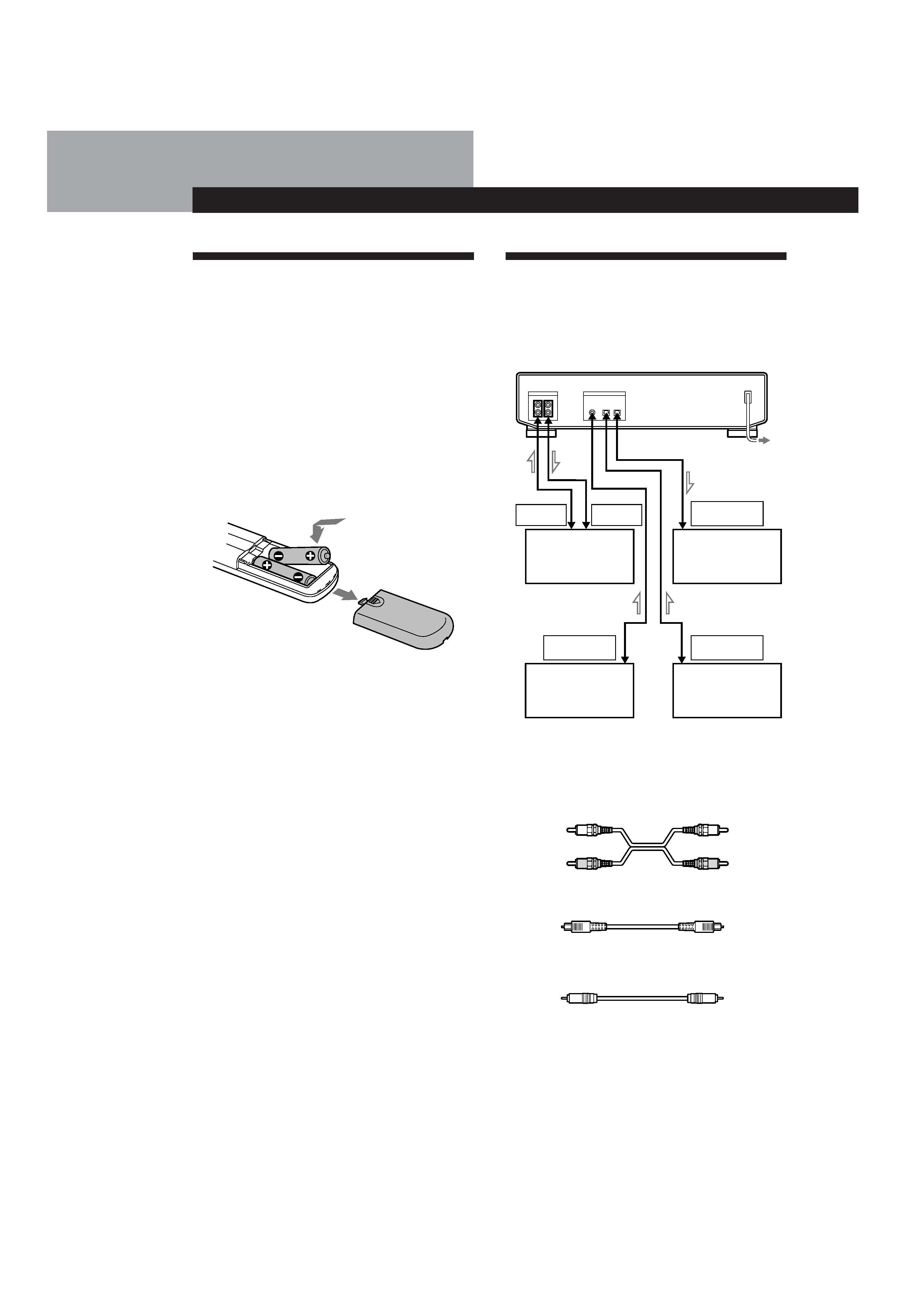
Inserting batteries into the remote
Insert two size-AA(R6) batteries, matching the + and
on the batteries with the markings inside the
battery compartment.
Getting Started
Hooking Up the System
This section describes how to hook up your deck to an
amplifier, CD player, MD deck, or other audio
components. Be sure to turn off the power to each
component before making the connections.
to a wall outlet
What cords will I need?
· Audio connecting cords (supplied) (2)
· Optical cables (POC-15 etc.) (not supplied) (2)
· Coaxial digital connecting cable (VMC-10G etc.)
(not supplied) (1)
White
(L)
Red
(R)
White
(L)
Red
(R)
z When to replace the batteries
With normal use, batteries should last for about 6
months. When the remote no longer operates the deck,
replace both batteries.
Notes
· Do not leave the remote near an extremely hot or humid
place.
· Do not drop any foreign matter into the remote casing,
particularly when replacing the batteries.
· Do not expose the remote sensor to direct sunlight or
illumination as doing so may cause malfunction.
· When not using the remote for an extended period of time,
remove the batteries to avoid possible damage from
battery leakage and corrosion.
Amplifier
etc.
CD player, DAT
deck, or MD deck,
etc.
CD player, DAT
deck, or MD deck,
etc.
CD player, DAT
deck, or MD deck,
etc.
ç: Signal flow
Basic
Operations
5
EN
Getting Started
3-858-189-11(1)
Ç
OUT
IN
OPTICAL
IN
COAXIAL
DIGITAL IN/OUT
COAXIAL
OUT
ç
Ç
OUT
IN
OPTICAL
IN
COAXIAL
DIGITAL IN/OUT
OPTICAL
IN
OUT
ç
Ç
OUT
IN
L
R
L
R
ANALOG IN/OUT
OUT
IN
L
R
L
R
LINE IN/OUT
Hookups
p Connecting the deck to an amplifier
Use the supplied audio connecting cords to connect
the deck to an amplifier. Be sure to match each
color-coded plug to the appropriate jack: red (right)
to red and white (left) to white. To prevent hum and
noise, be sure the connections are firmly made.
Note
If "PROHIBIT" appears in the display, recording through the
digital jack is not possible.
In this case, set the INPUT switch to ANALOG and record
the program source through the ANALOG IN jacks.
Connecting the AC power cord
Connect the AC power cord to a wall outlet.
Where do I go next?
Now you're ready to use your deck.
For basic operations, go to pages 6 to 8; for advanced
operations, go to the sections starting from page 9.
DAT deck
Amplifier
z When recording with a microphone
Connecting the analog output jakcs on the stereo
microphone amplifier to the ANALOG IN jacks of the
deck.
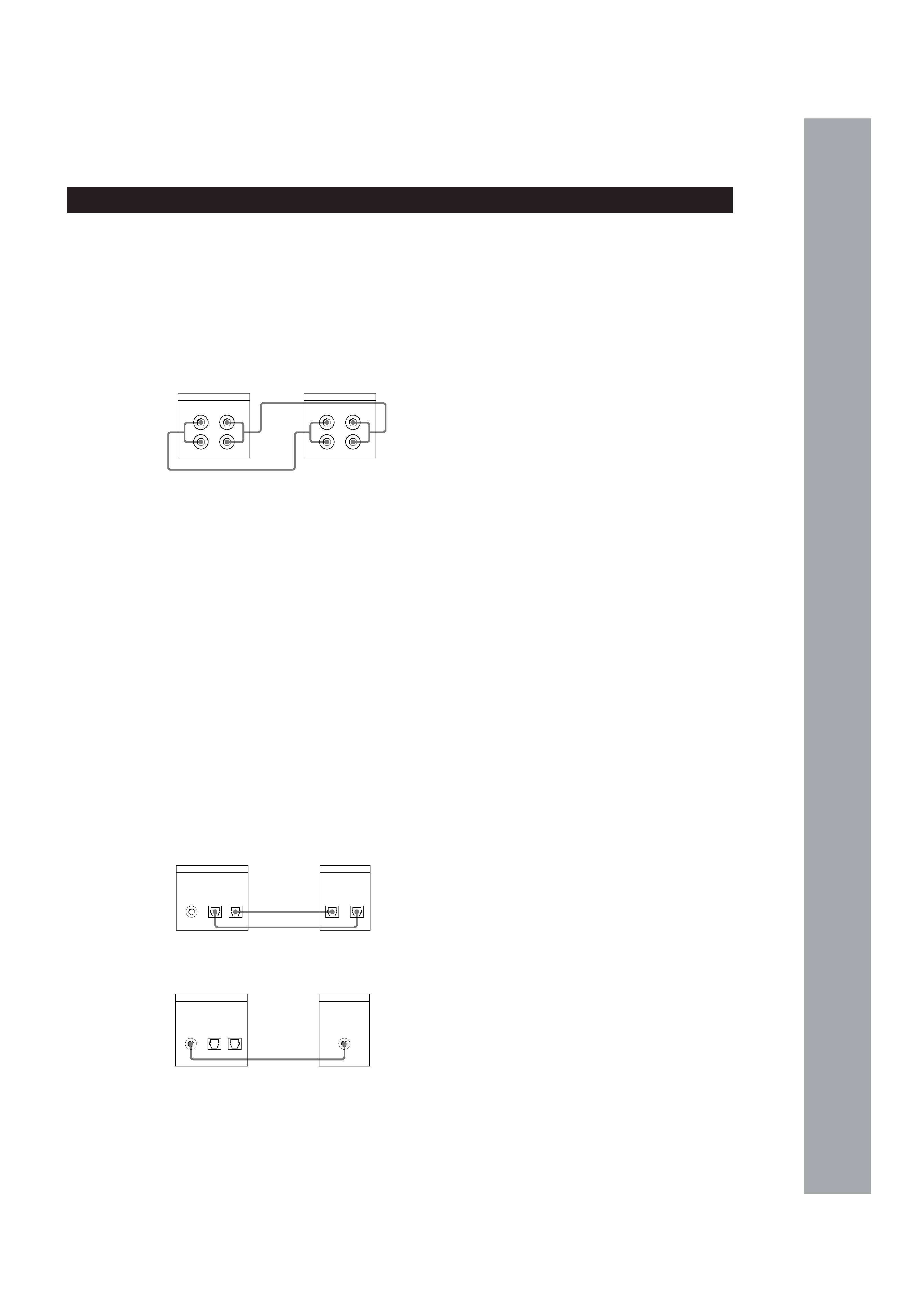
p Connecting the deck to a digital audio component
A digital audio signal from a digital audio
component such as a digital amplifier, DAT deck,
CD player, MD deck or BS tuner can be recorded on
the DAT deck by connecting the digital output
connectors on the component to the digital input
connectors (DIGITAL OPTICAL IN or DIGITAL
COAXIAL IN) on the deck.
A digital audio signal from the deck can be recorded
by connecting the digital output connector
(DIGITAL OPTICAL OUT) on the deck to the digital
input connector on a digital audio component such
as a digital amplifier, DAT deck or MD deck.
Use optical cables (POC-15A or equivalent) (not
supplied) or a coaxial digital connecting cable
(VMC-10G or equivalent) (not supplied).
· Connection with optical cables
DAT deck
Digital audio component
· Connection with coaxial digital connecting cable
Digital audio component
DAT deck