
- 1 -
TRINITRON® COLOR COMPUTER DISPLAY
OPERATION MANUAL
TROUBLESHOOTING MANUAL
CIRCUIT DESCRIPTION
D Board (Power Supply Section) ............. 2
D Board (Deflection Section) ................... 9
A Board .................................................. 20
GENERAL TROUBLESHOOTING .............. 26
PARTS LEVEL BOARD REPAIR ................ 37
D99 CHASSIS
TABLE OF CONTENTS
- 2 -
CIRCUIT DESCRIPTION
D BOARD POWER SUPPLY SECTION
Power Supply Electrical Circuit
The power supply is located on the D Board. It has three modes of operation that are controlled by a microprocessor. The
topology is a discontinuous mode flyback converter with photocoupler feedback for regulating the secondary voltages.
Circuit operation and troubleshooting are explained in the following sections:
Operation Modes
Secondary Circuitry
AC Input
Protection Circuits
Degauss Circuit
Troubleshooting
Primary Circuitry
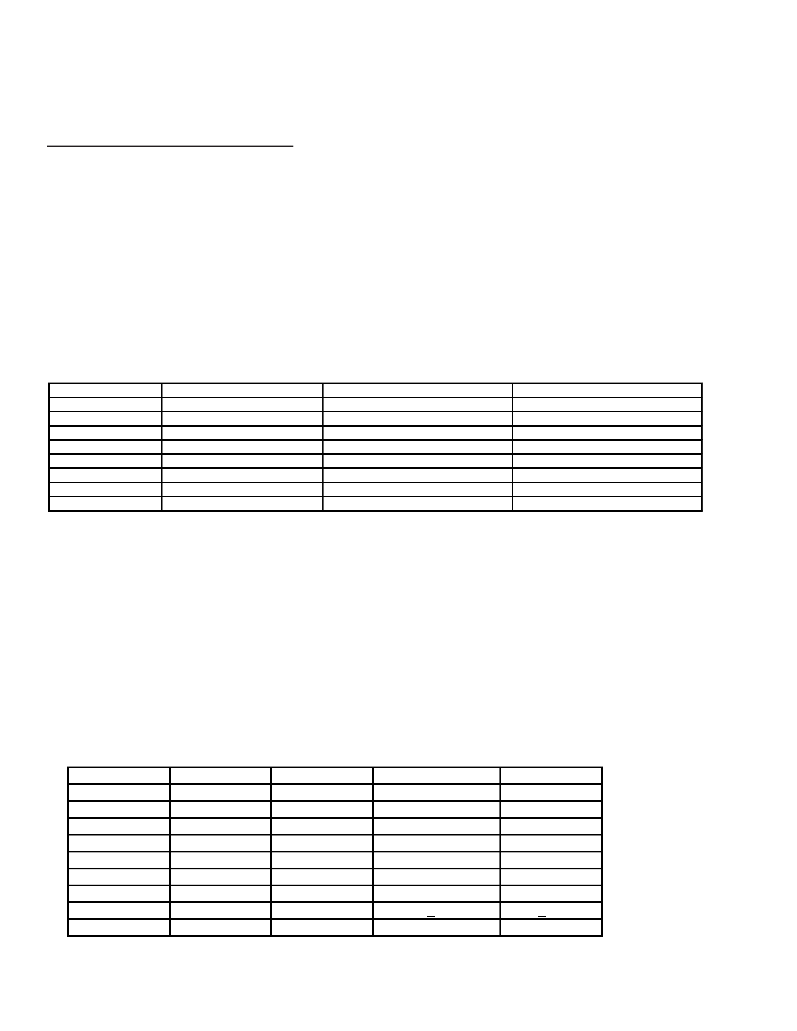
Operation Modes
The power supply has four modes of operation, `off', `active off', `suspend/standby' and `active on'. These modes are
related to power savings and are indicated by the front panel LED. Additional indications are failure diagnostics and aging
mode. The table below lists operation mode, condition and LED status.
Except for power switch off, all modes of operation are controlled by the microprocessor located on the D Board. The
failure modes are detected by the microprocessor and the power supply is forced into active off mode. These functions are
discussed later (Deflection).
With the AC cord attached to the monitor and connected to an AC source, the monitor will be off until the power switch is
turned on. When the power switch is turned on, the power supply starts and is in active off mode. The next step is active on
mode. The power saving modes are activated by the microprocessor based upon the presence of either H or V sync. If no
sync signals are present, the power supply is set to active off mode. If only horizontal sync is present the power supply
moves to suspend mode. If only vertical sync is present the power supply enters standby mode.
Power supply operation control signals are "Remote On/Off" and "Heater On/Off". Remote On/Off is digital low for active
off and suspend/standby modes. Heater On/Off is digital low for active off mode. To enter active on mode, the micropro-
cessor must set remote on/off to digital high. Heater on/off is also made digital high and the heater is turned on.
Output
Off
Active Off
Suspend/Standb y
Active On
B +
0V
13V
180V
180V
80V
0V
10V
77V
79V
+15V
0V
1V
14V
+15V
-15V
0V
-1 V
-14V
-15V
+12V
0V
0V
0V
+12V
5V
0V
0V
0V
+5V
H eater
0V
0V
4.6V
6.3V
H . C enterin g
0V
+ 7V
+ 10V
ST B Y 5V
0V
+5V
+5V
+5V
Mode
Syncs
Condition
LED
Off
N/A
Power Switch Off
Off
Active Off
No H and V
Low Power, Heater Off
Amber
Suspend/Standby
No H or V
Low Power, Heater On
Amber 0.5s<- ->Green 0.5s
Active On
H and V Present
Phase Locked, Normal Operation
Green
Failure 1
NA
HV or +B Failure
Amber 0.5s<- ->Off 0.5s
Failure 2
NA
H Stop, V Stop, Thermal Failure
Amber 1.5s<- ->Off 0.5s
Failure 3
NA
ABL Failure
Amber 0.5s<- ->Off 1.5s
Aging/Self Test
No H and V
Aging Raster or Test Pattern
Green 0.5s<- ->Off 0.5s
- 3 -
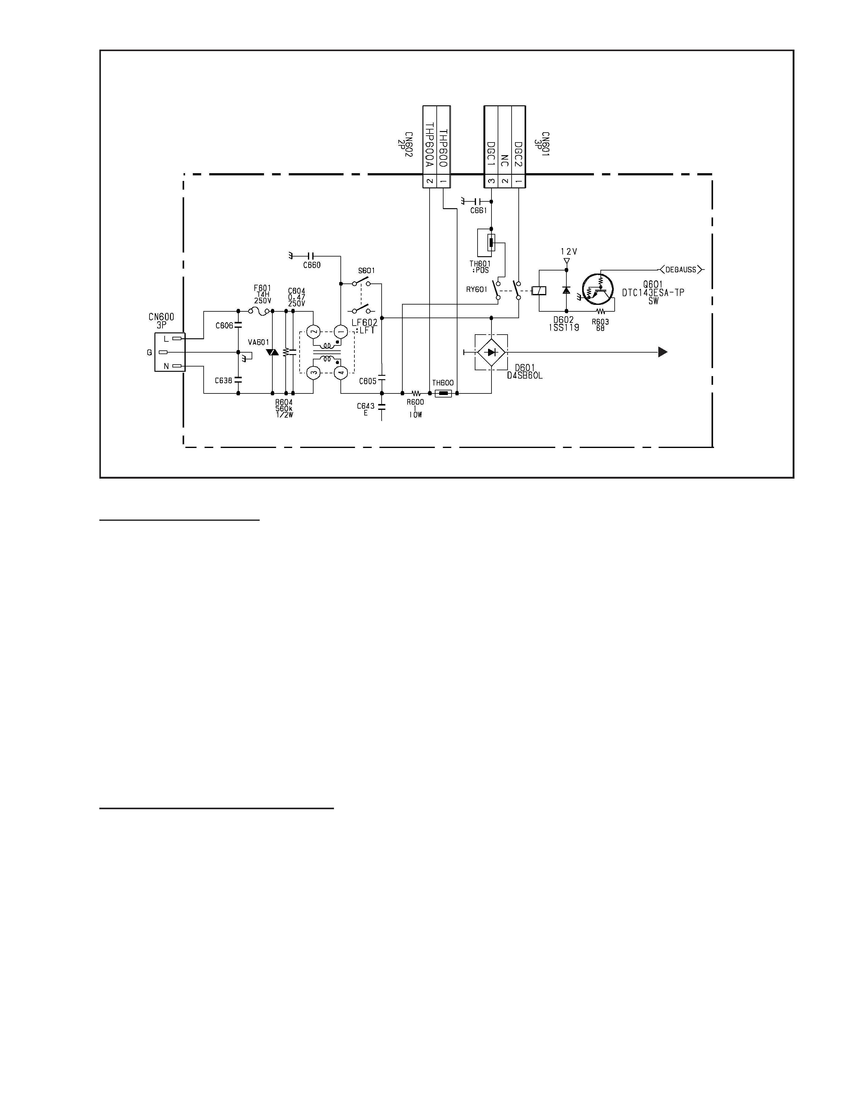
1. AC Input Section
The AC input section provides EMI filtering, input protection, surge limiting and CRT degauss operation.
EMI Filter
The EMI filter comprises CN600 (inlet with filter), X-capacitors C604 and C605, Y-capacitors C606, C638, C660 and
C643 and the line filter transformer, LF602. Input protection is provided by F601and VA601; surge current limiting by
thermistor TH600 and resistor R600. Degauss is explained in the next section.
Degauss Circuit
The degauss circuit is used to demagnetize the CRT. After power on, the microprocessor located on the D Board sets the
degauss signal to digital high and Q601 turns on relay RY601. This allows AC current into the degaussing coil through
posistor TH601. The current heats up the posistor and its affective resistance increases, this dampens the current in the
degauss coil to nearly zero. Duration time is approximately 5-6 seconds and the microprocessor then shuts off RY601,
which disconnects the degauss coil from the AC line. This operation should sufficiently demagnetize the CRT.
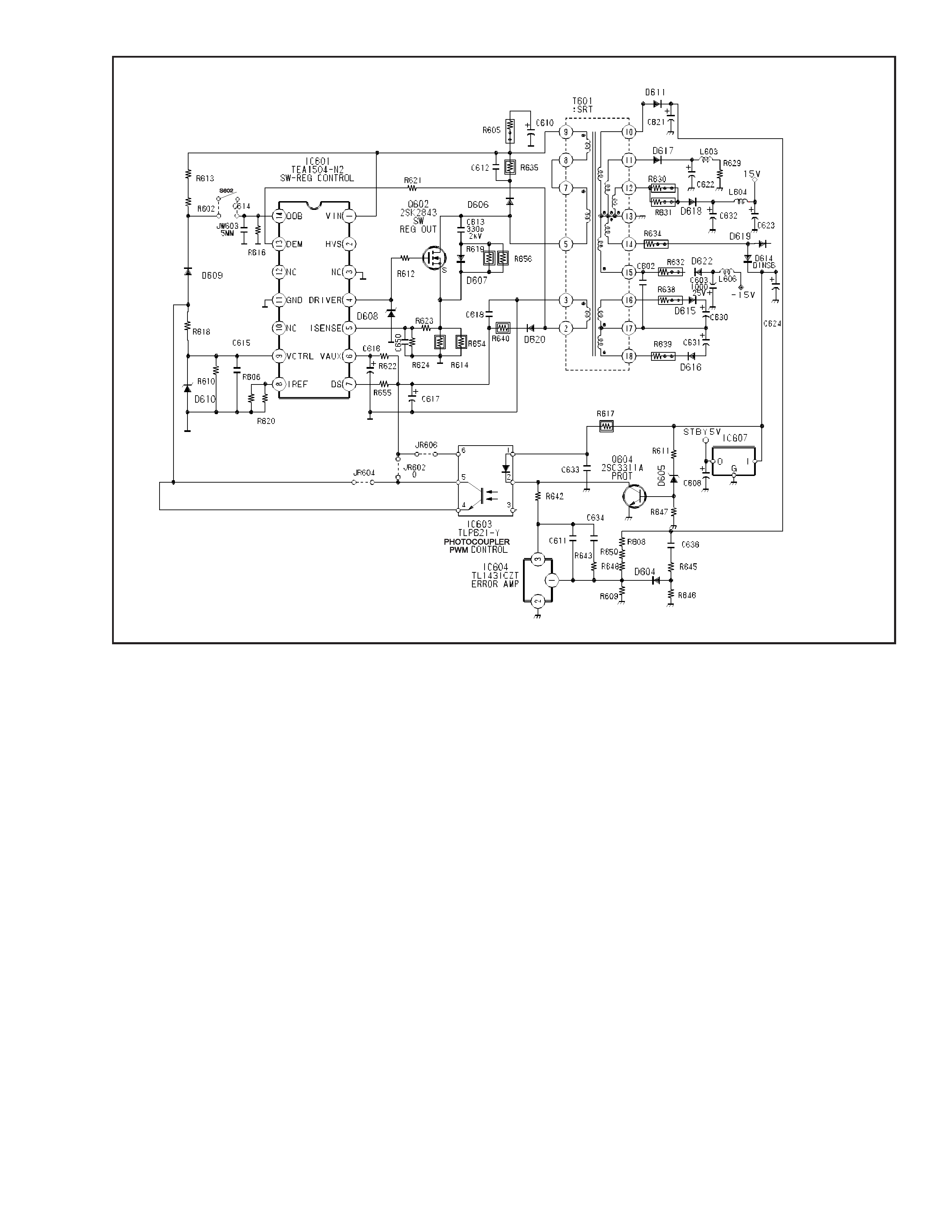
2. Primary Circuitry Section
IC601
The heart of the primary section is the TEA1504/N2 power supply controller, IC601. The following describes the functions
of each pin.
Pin 1 Vin: This is a MOSFET drain connection internal to IC601, which is connected directly to the DC mains voltage rail.
The startup current source derives power from the DC mains via the Vin pin. It supplies current to charge the Vaux (IC
supply) capacitors C616 and C617 and also provides current to the IC601 control circuitry.
Pin 2 HVS: High voltage safety spacer pin is a no connection.
Pin 3 NC: Connected to primary side DC mains return.
AC Input and Degauss

- 4 -
Pin 4 Driver: Outputs the pulse width modulated gate drive for switching transistor Q602. Maximum duty cycle is set
internally at 80%.
Pin 5 Isense: Provides cycle by cycle over current protection by turning off pin 4 driver output when Q602 current exceeds
the current limit corresponding to 500mV at pin 5. This pin typically provides 425nS of leading edge blanking time. The
threshold voltage for switch over to low frequency (low power) operation is sensed by pin 5. When the voltage sensed at pin
5 is below 165mV, IC601 transitions from operating at high frequency (56.5KHz) to low frequency (23.5KHz).
Pin 6 Vaux: IC601 supply pin. An internal current source from IC601 charges the Vaux capacitors C616 and C617 for
startup. Once the Vaux capacitors are charged to the startup voltage level (11V), then IC601 starts switching pin 4 driver
output. The Vaux is also supplied by an auxiliary winding from T601 on the primary side once the secondary output voltages
attain their nominal operating voltage values. Pin 6 also provides under voltage lockout detection (8V) and over voltage
protection (14.7V).
Pin 7 DS: Provides the power supply for the driver output (pin 4).
Pin 8 Iref: Controls IC601 internal bias currents, which determines the pulse width modulated switching frequencies.
High frequency is 56.5KHz during active on mode. Low frequency is 23.5KHz during suspend/standby mode.
Pin 9 Vctrl: Feedback voltage for duty cycle control.
Pin 10 NC: No connection.
Pin 11 Gnd: Connected to primary side DC mains return.
Pin 12 NC: No connection.
Pin 13 Dem: Guarantees discontinuous conduction mode operation for the power supply. Verifies that T601 is demagne-
tized by not activating the next gate drive pulse until the primary side auxiliary winding of T601 is lower than the threshold
level of 65mV as detected at pin 13.
Pin 14 OOB: On/Off/Burst mode input signal. A voltage greater than 2.5V enables IC601.
Operation
The power supply is a discontinuous-mode flyback converter with photocoupler feedback for regulating the secondary
voltages. The PWM controls the pulse width of the gate drive.
When AC is applied to the power supply and IC601 pin 14 is greater than 2.5V, start up current is supplied though IC601 pin
1 to IC601 pin 6. Startup voltage is approximately 11V. After start up, the voltage to pin 6 and pin 7 of IC601 is supplied
through D620 connected to T601 pin 2. The first mode of operation is active off mode. The output drive pulse frequency will
be in burst mode operation.
When the power supply enters active on mode, the switching frequency will be 56.5KHz. The Vaux level will be approxi-
mately 12.5 volts. OVP threshold is 14.7 volts and UVLO is 8.0 volts. Therefore, if the Vaux voltage is not correct, the power
supply will not operate properly.
Feedback from the secondary side comes through IC603 and IC604, which is connected to IC601 pin 9. (See diagram on
page 5.)
3. Secondary Circuitry Section
The secondary section consists of the following circuits. Rectifier diodes and filters for all output voltages, horizontal
centering, +5/12 volt regulators, +5 standby regulator, heater voltage regulator, voltage feedback circuit, active off mode
feedback, and protection circuits. This section will describe each circuit and its function.
Secondary Rectifiers
The secondary rectifiers supply the following voltages, 180V (B+) deflection and video, 80V video, ±15V deflection and
regulators, 6.3 volt heater regulator, +5V standby regulator, horizontal centering voltages.
- 5 -
Horizontal Centering
This circuit supplies IC503, which is used to adjust horizontal raster position on the CRT. The horizontal centering circuit
consists of fusible resistors R638 and R639, diodes D615 and D616 and filter capacitors C630 and C631. In respect to the
secondary ground, the horizontal centering ground is floating and connected to H DY line. The voltages in reference to this
floating ground are ±10 volts. Care should be taken to not short the floating ground to the secondary ground.
+5/12 Volt Regulator
IC605 is the 12 volt regulator and IC608 is the 5 volt regulator. The output voltages are supplied to the microprocessor,
deflection and video circuits. The +15 volt line provides the input voltage for +12V regulator; the +12V line provides the
input voltage for +5V regulator. During active off or suspend/standby mode, the 12 volt regulator is disabled via remote on/
off and subsequently the 5V regulator is disabled.
+5V Standby Circuit
IC607 is the standby 5V regulator. In the active on mode and the suspend/standby mode, the input to the regulator is supplied
from T601 winding 14-13. During the active off mode, the regulator input is supplied from T601 winding 10-13 via D612 and
D613. Typical input voltages to the regulator are active on mode: 9.5V; suspend/standby mode: 7.4V; active off mode: 11.5V.
Heater Voltage Regulator
Heater filament voltage is supplied by T601 winding 14-13 and is regulated by IC602. IC602 output is turned on and off by
the heater on/off control line at pin 1, CTL. The output is off during active off mode.
Feedback Circuit
The feed back circuit is divided into two sections. One is for active on and suspend/standby modes; the other for active
off mode. The following two sections explains the theory and operation.
Active On and Suspend/Standby Mode Feedback
Shunt regulator IC604 regulates the B+ line to 179.2V by sinking current through the opto coupler 1C603 to ground. The