CHASSIS
SERVICE MANUAL
SPECIFICATIONS
CPD-2001G
D-1H
COLOR COMPUTER DISPLAY
Equator Model
J Model
Chassis No. SCC-L07H-A
Picture tube
0.25 mm aperture grill pitch,
17 inches measured diagonally,
90 degree deflection
Viewable image size
Approx. 327
× 243 mm (w/h)
(12 7/8
× 9 5/8 in.)
16.0" viewing image
Resolution
Horizontal
Max. 1280 dots
Vertical
Max. 1024 lines
Display picture size
Approx. 312
× 234 mm (w/h)
(12 3/8
× 9 1/4 in.)
or
Approx. 293
× 234 mm (w/h)
(11 5/8
× 9 1/4 in.)
Deflection frequency
Horizontal
30 to 85 kHz
Vertical
50 to 120 Hz
AC input voltage/current
100 to 240 V, 50 60 Hz, 1.8 1.0
A
Dimensions
406
× 432 × 420 mm (w/h/d)
(16
× 17 1/8 × 16 5/8 in.)
Power consumption
Max.130W
Mass
Approx. 18 kg (39 lb 11 oz)
Design and specifications are subject to change without
notice.
CPD-2001G
2
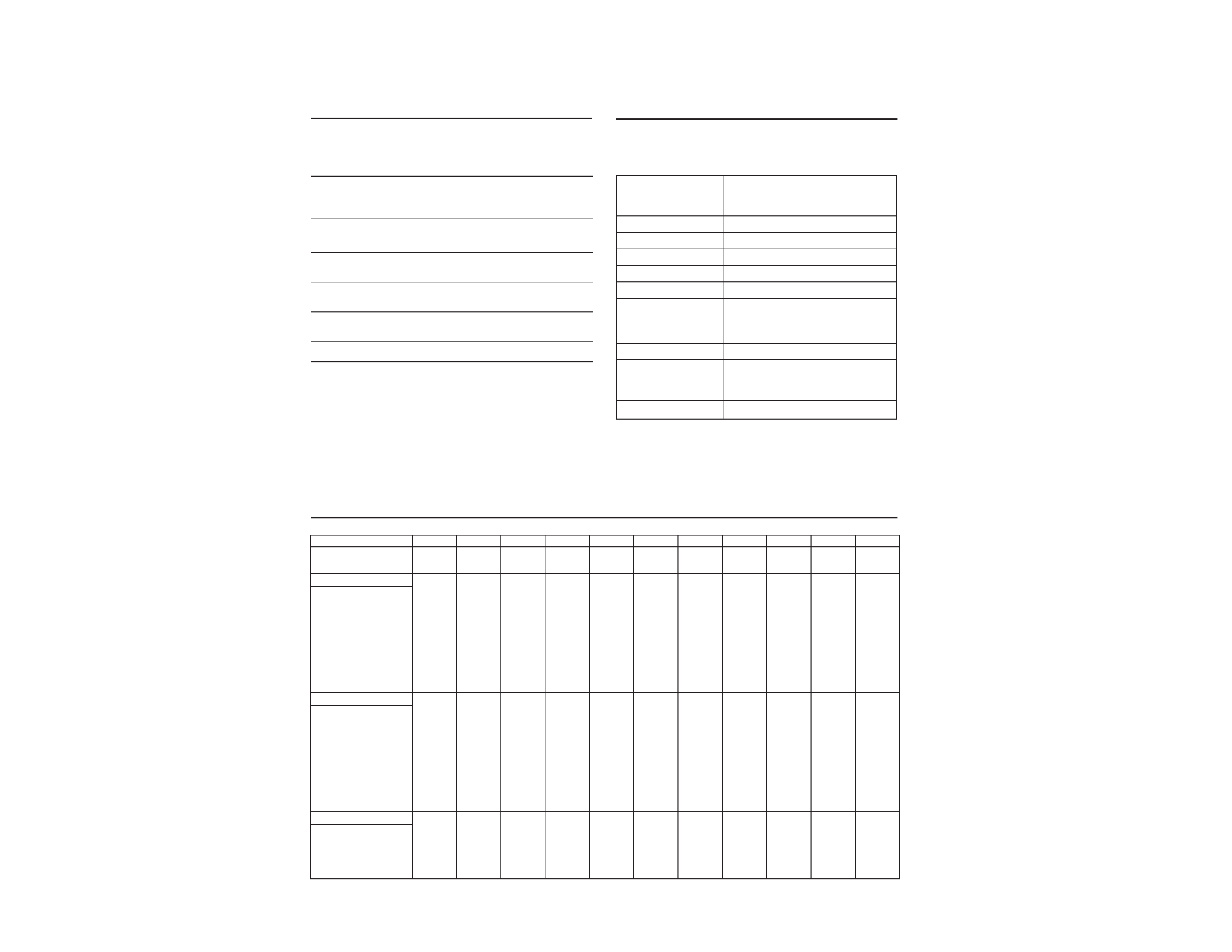
TIMING SPECIFICATION
POWER SAVING FUNCTION
DIAGNOSIS
MODE AT PRODUCTION
MODE 1
MODE 2
MODE 3
MODE 4
MODE 5
MODE 6
MODE 7
MODE 8
MODE 9
MODE 10
MODE 11
RESOLUTION
640 X 480
800 X 600
800 X 600
832 X 624
1024 X 768
1024 X 768
1024 X 768
720 X 400
640 X 480
1280 X 1024 1280 X 1024
CLOCK
25.175 MHZ
49.500 MHz
56.250 MHz
57.283 MHz
78.750 MHz
80.000 MHz
94.500 MHz
28.322 MHz
36.000 MHz 135.000 MHz 108.000 MHZ
-- HORIZONTAL --
H-FREQ
31.469 kHz
46.875 kHz
53.674 kHz
49.725 kHz
60.024 kHz
60.241 kHz
68.677 kHz
31.469 kHz
43.269 kHz
79.976 kHz
63.981 kHz
usec
usec
usec
usec
usec
usec
usec
usec
usec
usec
usec
H. TOTAL
31.778
21.333
18.631
20.111
16.66
16.600
14.561
31.777
23.111
12.504
15.63
H. BLK
6.356
5.172
4.409
5.586
3.657
3.800
3.725
6.355
5.333
3.022
3.778
H. FP
0.636
0.323
0.569
0.559
0.203
0.400
0.508
0.636
1.556
0.119
0.444
H. SYNC
3.813
1.616
1.138
1.117
1.219
1.2
1.016
3.813
1.556
1.067
1.037
H. BP
1.907
3.232
2.702
3.91
2.235
2.2
2.201
1.907
2.222
1.837
2.296
H. ACTIV
25.422
16.162
14.222
14.524
13.003
12.8
10.836
25.422
17.778
9.481
11.852
-- VERTICAL --
V. FREQ(HZ)
59.940 Hz
75.000 Hz
85.061 Hz
74.550 Hz
75.030 Hz
74.927 Hz
84.997 Hz
70.087 Hz
85.008 Hz
75.025 Hz
60.020 Hz
lines
lines
lines
lines
lines
lines
lines
lines
lines
lines
lines
V. TOTAL
525
625
631
667
800
804
808
449
509
1066
1066
V. BLK
45
25
31
43
32
36
40
49
29
42
42
V. FP
10
11
1131
12
111
V. SYNC
2
3
3
33332333
V. BP
33
21
27
39
28
30
36
35
25
38
38
V. ACTIV
480
600
600
624
768
768
768
400
480
1024
1024
-- SYNC --
INT(G)
NO
NO
NO
NO
NO
NO
NO
NO
NO
NO
NO
EXT(H/V)/POLARITY
YES -/-
YES +/+
YES +/+
YES -/-
YES +/+
YES -/-
YES +/+
YES -/+
YES +/+
YES +/+
YES +/+
EXT(CS)/POLARITY
NO
NO
NO
NO
NO
NO
NO
NO
NO
NO
NO
INT/NON INT
NON INT
NON INT
NON INT
NON INT
NON INT
NON INT
NON INT
NON INT
NON INT
NON INT
NON INT
This monitor has three Power Saving modes. By sensing the
absence of a video signal from the computer, it reduces power
consumption as follows.
Note
If no video signal is input to the monitor, the "NO INPUT
SIGNAL" message appears (page 12). After about 30 seconds, the
Power Saving function automatically puts the monitor into
active-off mode and the u indicator lights up orange. Once the
monitor detects horizontal and vertical sync signals, the monitor
automatically resumes normal operation mode.
1
2
3
4
5
Power
consumption
mode
Normal
operation
Standby
(1st mode)
Suspend
(2nd mode)
Active-off
(3rd mode)
Power-off
Power
consumption
110 W
15 W
15 W
8 W
0 W
Recovery
time
--
Approx.
3 sec.
Approx.
3 sec.
Approx.
15 sec.
--
u
indicator
Green
Green and orange
alternate
Green and orange
alternate
Orange
Off
Power LED
Normal On
GREEN
Stand-by
ORANGE(0.5sec)/GREEN(0.5sec)...
Suspend
ORANGE(0.5sec)/GREEN(0.5sec)/...
Active Off
ORANGE
HV or +B failure
ORANGE(0.5sec)/OFF(0.5sec)/...
H stop or V stop
ORANGE(1.5sec)/OFF(0.5sec)/...
(Includes S correction
capacitor failure)
ABL failure
ORANGE(0.5sec)/OFF(1.5sec)/...
Aging/Self Test
ORANGE(0.5sec)/OFF(0.5sec)/
GREEN(0.5sec)/OFF(0.5sec)/
ORANGE(0.5sec)/...
Out of Range
GREEN(OSD indication)
DIH PLUS has one power LED which has two colors(Green and
Orange). Some monitor status are indicated by using this LED as
follows.

CPD-2001G
3
Section
Title
Page
1. GENERAL ................................................................. 1-1
2. DISASSEMBLY
2-1.
Cabinet Removal ............................................... 2-1
2-2.
Service Position .................................................. 2-1
2-3.
A and D Boards Removal ................................. 2-1
2-4.
Picture Tube Removal ....................................... 2-2
3. SAFETY RELATED ADJUSTMENT ............. 3-1
4. ADJUSTMENTS ..................................................... 4-1
5. DIAGRAMS
5-1.
Block Diagrams .................................................. 5-1
5-2.
Circuit Boards Location ..................................... 5-4
5-3.
Schematic Diagrams and Printed Wiring
Boards ................................................................. 5-4
(1)
Schematic Diagram of D Board ........................ 5-5
(2)
Schematic Diagram of A Board ........................ 5-12
5-4.
Semiconductors ................................................. 5-16
WARNING!!
NEVER TURN ON THE POWER IN A CONDITION IN
WHICH THE DEGAUSS COIL HAS BEEN REMOVED.
SAFETY-RELATED COMPONENT WARNING!!
COMPONENTS IDENTIFIED BY SHADING AND MARK
¡ ON THE SCHEMATIC DIAGRAMS, EXPLODED
VIEWS AND IN THE PARTS LIST ARE CRITICAL FOR
SAFE OPERATION. REPLACE THESE COMPONENTS
WITH SONY PARTS WHOSE PART NUMBERS AP-
PEAR AS SHOWN IN THIS MANUAL OR IN SUPPLE-
MENTS PUBLISHED BY SONY. CIRCUIT ADJUST-
MENTS THAT ARE CRITICAL FOR SAFE OPERATION
ARE IDENTIFIED IN THIS MANUAL. FOLLOW THESE
PROCEDURES WHENEVER CRITICAL COMPONENTS
ARE REPLACED OR IMPROPER OPERATION IS SUS-
PECTED.
Section
Title
Page
6. EXPLODED VIEWS
6-1.
Chassis ............................................................... 6-1
6-2.
Packing Materials .............................................. 6-2
7. ELECTRICAL PARTS LIST ............................ 7-1
8. DIFFERENT POINT OF J MODEL
(WITH EQ MODEL)
8-1.
Schematic Diagram of D Board
(J Model) ............................................................ 8-1
8-2.
Electrical Parts List (J Model) ........................... 8-2
TABLE OF CONTENTS
SECTION 1
GENERAL
1-1
The operating instructions mentioned here are partial abstracts
from the Operating Instruction Manual. The page numbers of
the Operating Instruction Manual remain as in the manual.
3
Getting Started
J
C
EN
Table of Contents
Installation
· Prevent internal heat build up by allowing adequate air
circulation. Do not place the monitor on surfaces (rugs,
blankets, etc.) or near materials (curtains, draperies) that
may block the ventilation holes.
· Do not install the monitor near heat sources such as
radiators or air ducts, or in a place subject to direct
sunlight, excessive dust, mechanical vibration or shock.
· Do not place the monitor near equipment that generates
magnetism, such as a converter, or high voltage power
lines.
Maintenance
· Clean the cabinet, panel and controls with a soft cloth
lightly moistened with a mild detergent solution. Do not
use any type of abrasive pad, scouring powder or solvent
such as alcohol or benzine.
· Do not rub, touch or tap the surface of the screen with
sharp or abrasive items such as a ball point pen or
screwdriver. This type of contact may scratch the picture
tube.
· Clean the screen with a soft cloth. If you use a glass
cleaning liquid, do not use any type of cleaner containing
an anti-static solution or similar additive as this may
scratch the screen's coating.
Transportation
· When you transport this monitor for repair or shipment,
use the original carton and packing material.
WarningonPowerConnection
· Use an appropriate power cord for your local power
supply.
for 220 to 240 V AC
for 100 to 120 V AC
· Before disconnecting the power cord, wait for at least 30
seconds after turning off the power to allow the static
electricity on the CRT display surface to discharge.
· After the power has been turned on, the CRT is
demagnetized (degaussed) for about 5 seconds. This
generates a strong magnetic field around the metal frame,
which may affect the data stored on magnetic tapes and
disks near the monitor. Place magnetic recording
equipment, tapes and disks away from this monitor.
Precautions
Examples of plug types:
for 240 V AC only
The socket should be installed near the equipment and
be easily accessible.
Precautions ............................................................................... 3
Setup .......................................................................................... 4
Parts and Controls ................................................................... 4
The OSD (On-screen Display) System ................................. 6
Resetting the Adjustments ..................................................... 9
Video Enhancement Mode ................................................... 10
Specifications .......................................................................... 10
Monitor Information ............................................................. 10
Power Saving Function and LED Indicator ...................... 11
Plug and Play ......................................................................... 11
Damper wires ......................................................................... 11
Warning Messages ................................................................. 12
Troubleshooting ..................................................................... 12
Getting Started
4
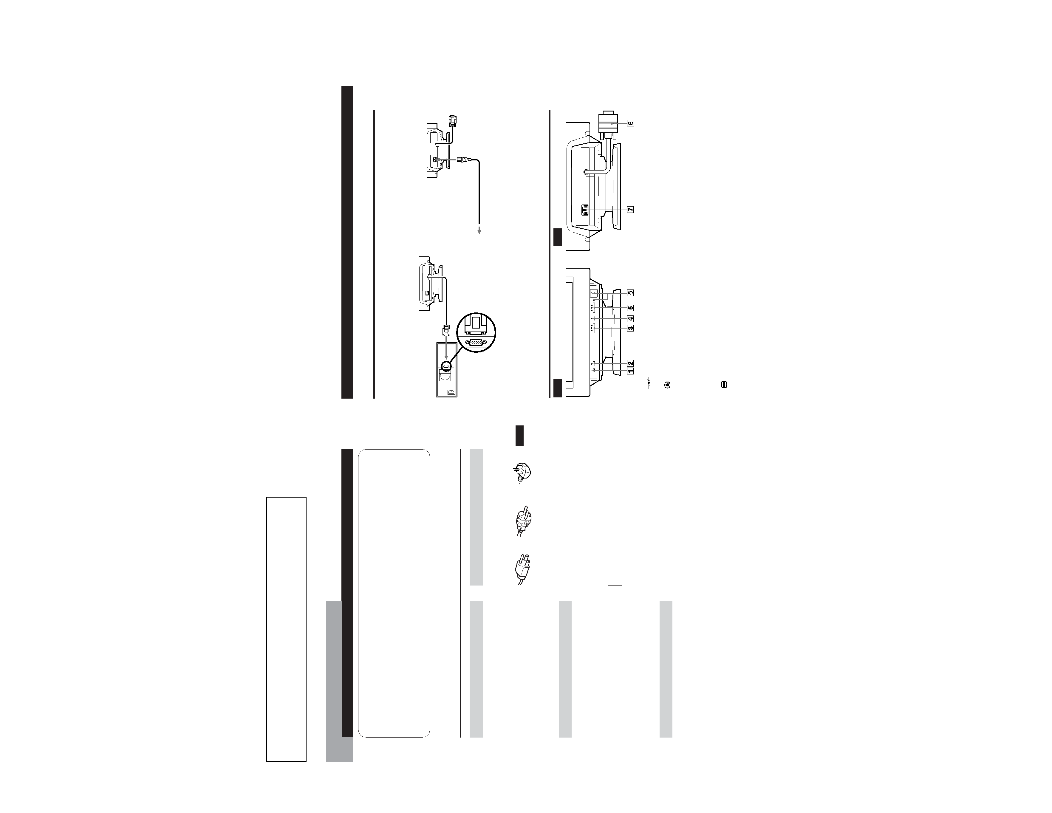
PartsandControls
Rear
1
(RESET) button (pages 6 and 9)
Resets the adjustments to the factory settings.
2
Video Enhancement Mode button
(page 10)
Selects the Video Enhancement Mode.
3 ¨ (BRIGHTNESS) ./> buttons (page 5)
Adjust the picture brightness.
Operate as the ./> buttons when adjusting other
items.
4
(MENU) button (pages 6 and 10)
Displays the MENU OSD.
5 > (CONTRAST) ?// buttons (page 5)
Adjust the contrast.
Operate as the ?// buttons when adjusting other
items.
6 u (POWER) switch and indicator (page 11)
Turns the monitor on and off.
The indicator lights up green when the monitor is on,
and lights up green and orange when the monitor is in
Power Saving mode.
7 AC IN connector
Provides AC power to the monitor.
8 Video input connector (HD15)
Inputs RGB video signals and SYNC signals
Front
Getting Started
Step 2 Make sure the monitor is switched off and attach the
power cord to the monitor. Then, attach the other end
of the power cord to a power outlet.
Step 3 Switch on the monitor and computer.
Step 4 Adjust the user controls according to your personal
preference.
Installation is complete.
Power cord
to a power outlet
Setup
Connect the monitor to your computer system.
This monitor will sync to platforms running at horizontal frequencies between 30 and 85 kHz.
Step 1 Make sure the computer system is switched off and
attach the video signal cable to the video output of the
computer.
to the video output
Computer
to AC IN
1-2
5
Getting Started
J
C
EN
VideoConnector
Pin No.
Signal
8
Blue Ground
9
Not used (no pin)
10
Ground
11
Ground
12
SDA (serial data)
13
Horizontal Sync
14
Vertical Sync
15
SCL (serial clock)
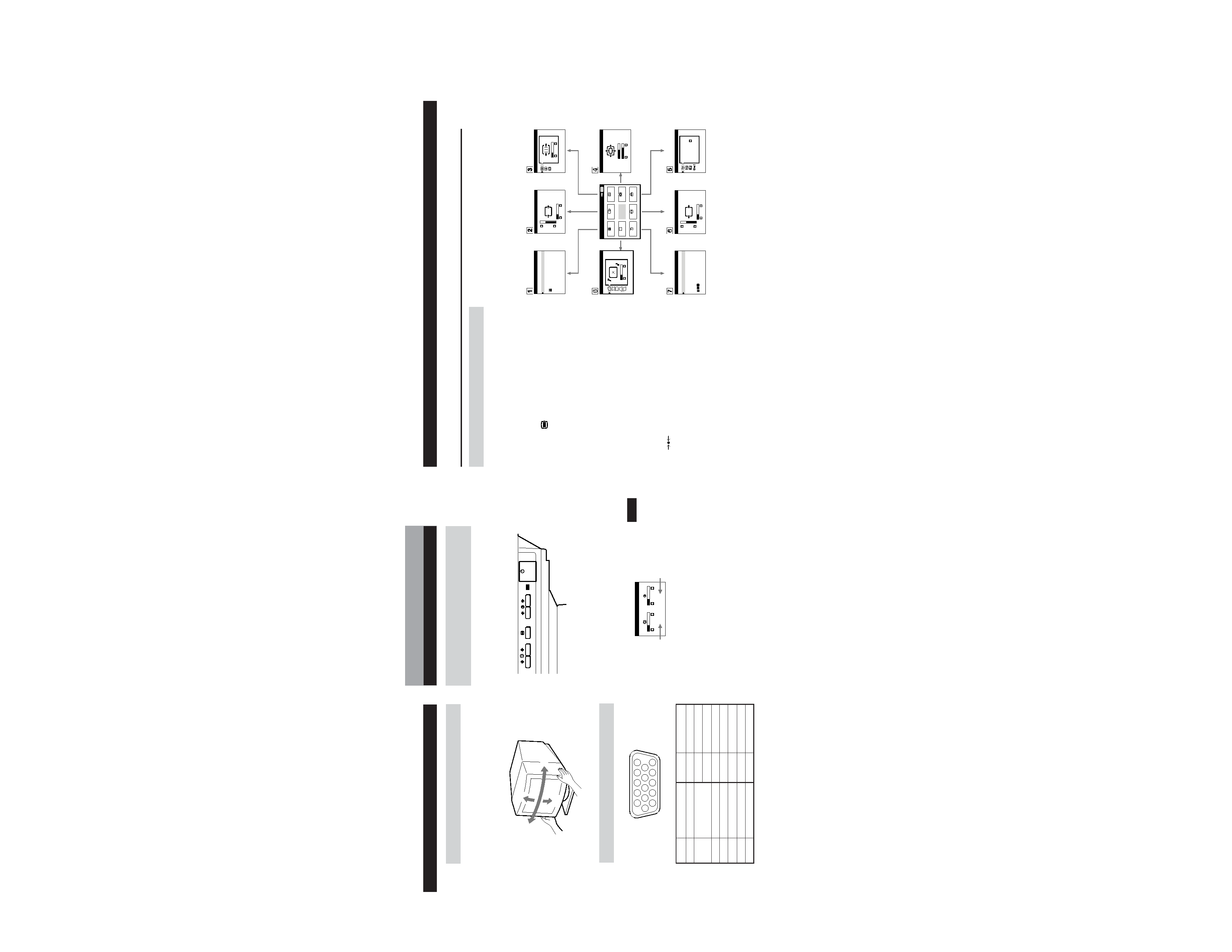
UseoftheTilt/Swivel
With the tilt/swivel, you can adjust this monitor to any desired
angle within 180° horizontally and 20° vertically.
To turn the monitor vertically and horizontally, hold it at the
bottom with both hands as shown below.
Getting Started
AdjustingthePictureBrightnessand
Contrast
1 Press the ¨ (BRIGHTNESS) ./> or
>
(CONTRAST) ?// buttons.
The BRIGHTNESS/CONTRAST OSD appears.
2 To adjust the brightness
Press the ¨ (BRIGHTNESS) ./> buttons.
To adjust the contrast
Press the > (CONTRAST) ?// buttons.
Horizontal
frequency
Vertical
frequency
15
°
90
°
90
°
5
°
6
11 12 13 14 15
12
3
4
5
78
9 10
Customizing Your Monitor
BRIGHTNESS/CONTRAST
26
26
60.0kHz/ 85Hz
Note
The default setting for the OSD Language is Japanese. If you need
to change the OSD Language, see "Using the LANGUAGE OSD"
on page 8.
Pin No. Signal
1
Red
2
Green (Composite
Sync on Green)
3
Blue
4
Ground
5
DDC Ground
6
Red Ground
7
Green Ground
6
TheOSD(On-screenDisplay)System
IntroducingtheOSDSystem
You can adjust most of the monitor's settings using the OSDs
(On-screen Display). All of the OSDs numbered in this
illustration are described on the following pages in order. You
can access any of these OSDs from the MENU OSD. To adjust
monitor settings using the OSDs, follow the steps below:
Basiccontrols:
· Use the
(MENU) button to display the MENU OSD
and to select menu items.
· Use the ¨ (BRIGHTNESS) ./> and > (CONTRAST)
?// buttons to highlight menu items and to adjust
settings.
Toadjustthemonitorsettings:
1 Press the MENU button to display the MENU OSD.
2 Highlight the desired OSD using the BRIGHTNESS and
CONTRAST buttons and press the MENU button again.
3 If necessary, use the BRIGHTNESS buttons to select a
specific item.
4 Adjust the monitor setting using the BRIGHTNESS and
CONTRAST buttons.
· To reset the current item to its original setting, press the
(RESET) button while the item's adjustment OSD
is displayed.
5 When you finish adjusting the setting, press the MENU
button to return to the MENU OSD.
Press the MENU button twice to return to normal viewing.
· Resetting: If you press the RESET button while an OSD is
displayed, only the current adjustment item is reset. For
additional information on using the reset function, see
the "Resetting the Adjustments" section on page 9.
· The OSD automatically disappears after 30 seconds.
Note
The default setting for the OSD Language is Japanese. If you need
to change the OSD Language, see "Using the LANGUAGE OSD"
on page 8.
COLOR
CENTER
SCREEN
GEOMETRY
ZOOM
LANGUAGE
OPTION
SIZE
Customizing Your Monitor
MENU
EXIT
CENTER
SIZE
GEOM
COLOR
LANG
ZOOM
SCREEN
OPTION
OK
MENU
ENGLISH
FRANÇAIS
DEUTSCH
ESPAÑOL
LANGUAGE
SIZE
26
73
CENTER
26
73
ZOOM
73
V
66
H
ROTATION
GEOMETRY
26
9300K
5000K
COLOR
MANUAL DEGAUSS
OPTION
ON
H CONVERGENCE
SCREEN
26