CMT-C5
AEP Model
UK Model
Australian Model
E Model
SERVICE MANUAL
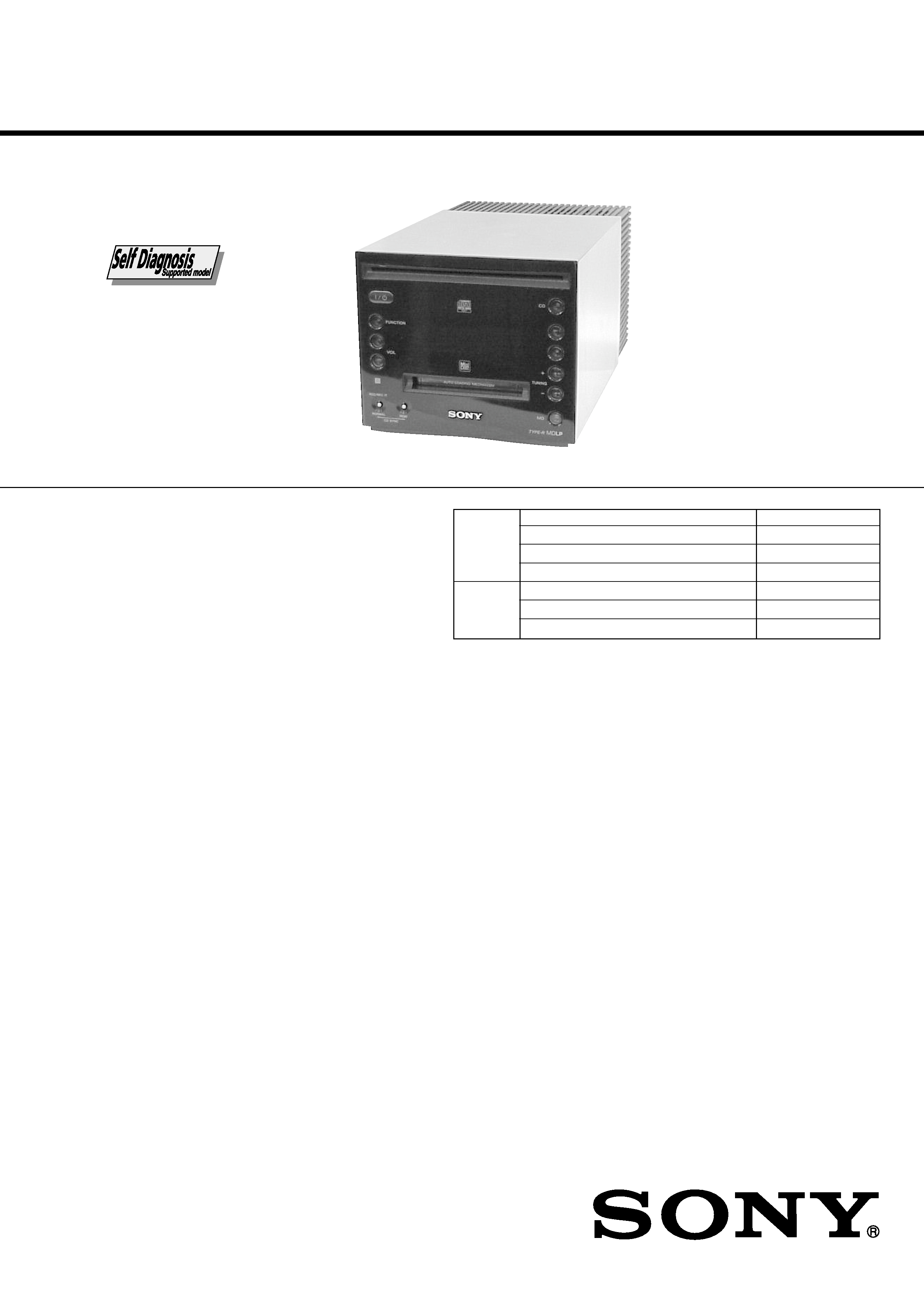
MICRO HI-FI COMPONENT SYSTEM
Sony Corporation
Home Audio Company
Shinagawa Tec Service Manual Production Group
9-873-229-01
2001G1600-1
© 2001.7
· CMT-C5 is composed of following model.
As for the service manual, it is issued for each component
model, then, please refer to it.
Ver 1.0 2001. 07
COMPONENT MODEL NAME
HCD-C5
SA-C5B
Part No.
Description
Remarks
ACCESSORIES & PACKING MATERIALS
********************************
1-476-649-21 COMMANDER, CARD (RM-SC5BEN)
1-501-374-11 ANTENNA, LOOP (AM)
1-501-594-11 ANTENNA (FM) (AEP, UK, KR)
1-501-659-41 ANTENNA (FM) (AUS, HK)
0 1-770-019-11 ADAPTOR, CONVERSION PLUG 3P (UK, HK)
4-233-942-11 MANUAL, INSTRUCTION (ENGLISH)
4-233-942-21 MANUAL, INSTRUCTION (FRENCH, SPANISH)
(AEP)
4-233-942-31 MANUAL, INSTRUCTION
(GERMAN, DUTCH, ITALIAN) (AEP)
4-233-942-41 MANUAL, INSTRUCTION (SWEDISH, POLISH) (AEP)
4-233-942-51 MANUAL, INSTRUCTION (CHINESE) (HK)
4-233-942-61 MANUAL, INSTRUCTION (KOREAN) (KR)
4-234-860-11 MANUAL, INSTRUCTION (GREEK) (AEP)
4-234-860-21 MANUAL, INSTRUCTION (HUNGARIAN, CZECH)
(AEP)
4-234-860-31 MANUAL, INSTRUCTION (TURKISH) (AEP)
4-234-860-41 MANUAL, INSTRUCTION (SLOVAK) (AEP)
4-236-290-21 COVER, BATTERY (FOR RM-SC5BEN)
4-236-313-11 MANUAL, INSTRUCTION (DANISH,FINNISH) (AEP)
4-236-313-21 MANUAL, INSTRUCTION (PORTUGUESE) (AEP)
4-236-313-31 MANUAL, INSTRUCTION (RUSSIAN) (AEP)
· Abbreviation
AUS : Australian model.
KR
: Korea model.
HK
: Hong Kong model.
PARTS LIST
COMPACT DISC DECK
RECEIVER SYSTEM
SPEAKER SYSTEM
The components identified by mark 0 or dotted
line with mark 0 are critical for safety.
Replace only with part number specified.
MC-Service
HCD-C5
AEP Model
UK Model
SERVICE MANUAL
MICRO HI-FI COMPONENT SYSTEM
Sony Corporation
Home Audio Company
Shinagawa Tec Service Manual Production Group
9-873-244-01
2001G1600-1
© 2001.7
SPECIFICATIONS
Ver 1.0 2001. 07
HCD-C5 is the Amplifier, CD player, MD
Deck and Tuner section in CMT-C5.
Model Name Using Similar Mechanism
New
CD Mechanism Type
TN-CCD1001Z
Base Unit Name
TT BASE ASSY
Optical Pick-up Name
OPTIMA-720L1E
Model Name Using Similar Mechanism
New
MD Mechanism Type
MDM-7B4M
Optical Pick-up Name
KMS-260E/Z-NP
CD
Section
MD
Section
Amplifier section
DIN power output (rated): 15 + 15 W
(6 ohms at 1 kHz, DIN)
Continuous RMS power output (reference):
20 + 20 W
(6 ohms at 1 kHz, 10%
THD)
Music power output (reference):
45 + 45 W
Inputs
TAPE IN (stereo minijack):
Sensitivity 250 mV,
impedance 47 kilohms
DIGITAL OPTICAL IN (Supported sampling
frequencies: 32 kHz, 44.1 kHz and 48 kHz)
Outputs
TAPE OUT (stereo minijack):
Sensitivity 250 mV,
impedance 1 kilohmes
PHONES (stereo minijack):
Accepts headphones with
an impedance of 8 ohms
or more
Mass
General
Power requirements
230 V AC, 50/60 Hz
Power consumption
See the nameplate
0.5 W (at the power
saving mode)
Dimensions (w/h/d)
Approx. 145
× 125 ×
273 mm incl. projecting
parts and controls
Approx. 4.5 kg
Supplied accessories
Remote commander (1)
AM loop antenna (1)
FM wire antenna (1)
Design and specifications are subject to change
without notice.
MD deck section
System
MiniDisc digital audio
system
Laser
Semiconductor laser
(
= 780 nm)
Emission duration:
continuous
Sampling frequency
44.1 kHz
Frequency response
5 Hz 20 kHz
Tuner section
FM stereo, FM/AM superheterodyne tuner
FM tuner section
Tuning range
87.5 108.0 MHz
(50-kHz step)
Antenna
FM wire antenna
Antenna terminals
75 ohm unbalanced
Intermediate frequency
10.7 MHz
AM tuner section
Tuning range
531 1,602 kHz
(with the tuning interval
set at 9 kHz)
Antenna
AM loop antenna, external
antenna terminal
Intermediate frequency
450 kHz
CD player section
System
Compact disc and digital
audio system
Laser
Semiconductor laser
(
= 780 nm)
Emission
duration: continuous
Frequency response
2 Hz 20 kHz
MC-Service
2
HCD-C5
SELF-DIAGNOSIS FUNCTION
The self-diagnosis function consists of error codes for customers, which are displayed automatically when errors occur,
and error codes, which show the error history in the test mode during servicing. For details on how to view error codes
for the customer, refer to the following box in the instruction manual. For details on how to check error codes during
servicing, refer to the following "Procedure for using the Self-Diagnosis Function (Error History Display Mode)".
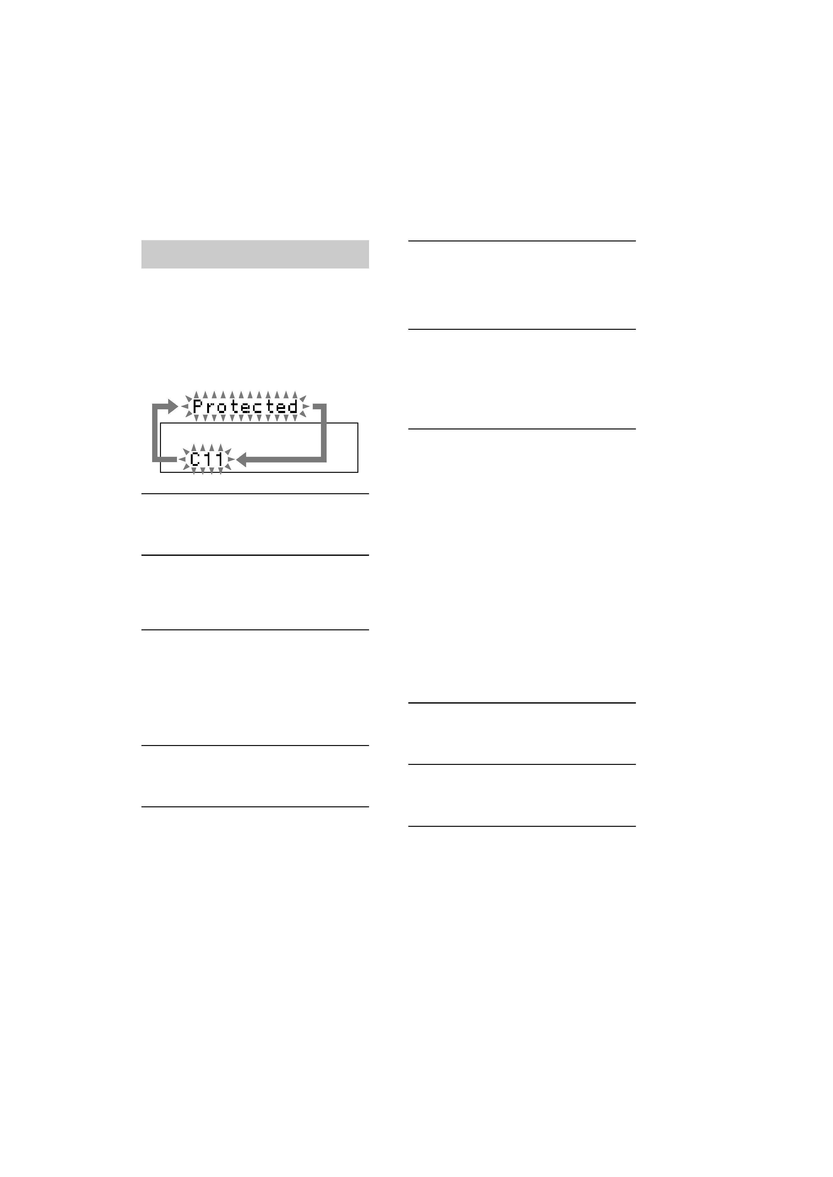
Self-diagnosis display
This system has a Self-diagnosis display
function to let you know if there is a system
malfunction. The display shows a code made
up of 3 or 5 letters and a message alternately to
show you the problem. To solve the problem
refer to the following list. If any problem
persists, consult your nearest Sony dealer.
C11/Protected
The MD is protected against erasure.
cRemove the MD and slide the tab to close the
slot (see page 18).
C12/Cannot Copy
You tried to record a CD or MD with a format that
the system does not support, such as a CD-ROM.
cRemove the disc and turn off the system once,
then turn it on again.
C13/REC Error
Recording could not be performed properly.
cMove the system to a stable place, and start
recording over from the beginning.
The MD is dirty or scratched, or the MD does not
meet the standards.
cReplace the MD and start recording over from
the beginning.
C13/Read Error
The MD deck cannot read the disc information
properly.
cRemove the MD once, then load it again.
E0101/LASER NG
There is a problem with the optical pickup.
cThe optical pickup may have failed. Consult your
nearest Sony dealer.
C14/Toc Error
The MD deck cannot read the disc information
properly.
cReplace the MD.
Erase all the recorded contents of the MD using
All Erase Function (see page 29).
C41/Cannot Copy
The sound source is a copy of a commercially
available music software, or you tried to record a
CD-R (Recordable CD).
cThe Serial Copy Management System prevents
making a digital copy (see page 48). You cannot
record a CD-R.
C71/Check OPT-IN
This appears momentarily because of the signal of
the digital broadcast during recording.
cThere is no affect on the recorded contents.
No component is connected to the DIGITAL
OPTICAL IN jack, or a digital component is not
connected properly.
cConnect a digital component to the DIGITAL
OPTICAL IN jack properly using a digital
connecting cable (not supplied, see page 43).
The connected digital component is not turned on.
cSee the operating instructions supplied with the
connected component and confirm whether the
component is turned on.
The digital connecting cable connected to the
DIGITAL OPTICAL IN jack is pulled out, or the
connected digital component is turned off during
digital recording.
cConnect the cable, or turn on the digital
component.
E0001/MEMORY NG
There is an error in the internal data that the system
needs in order to operate.
cConsult your nearest Sony dealer.

3
HCD-C5
TABLE OF CONTENTS
SELF-DIAGNOSIS FUNCTION ..................................... 2
1.
SERVICING NOTES ............................................... 4
2.
GENERAL ................................................................... 7
3.
DISASSEMBLY ......................................................... 9
4.
TEST MODE ............................................................... 24
5.
ELECTRICAL ADJUSTMENTS
CD Section ...................................................................... 33
MD Section ..................................................................... 34
6.
DIAGRAMS
6-1. NOTE FOR PRINTED WIRING BOARDS AND
SCHEMATIC DIAGRAMS ............................................ 45
Wave forms ................................................................... 45
Circuit Boards Location ............................................... 45
6-2. Block Diagram CD Servo Section ............................ 46
6-3. Block Diagram MD Servo Section ........................... 47
6-4. Block Diagram MAIN Section ................................. 48
6-5. Printed Wiring Boards CD Section .......................... 49
6-6. Schematic Diagram CD Section ............................... 50
6-7. Printed Wiring Board BD (MD) Board .................... 51
6-8. Schematic Diagram BD (MD) Board (1/2) .............. 52
6-9. Schematic Diagram BD (MD) Board (2/2) .............. 53
6-10. Printed Wiring Board MD DIGITAL Board ............ 54
6-11. Schematic Diagram MD DIGITAL Board ............... 55
6-12. Printed Wiring Board UCOM Board ........................ 56
6-13. Schematic Diagram UCOM Board ........................... 57
6-14. Printed Wiring Boards AUDIO Section .................... 58
6-15. Schematic Diagram AUDIO Section ........................ 59
6-16. Printed Wiring Board PANEL Board ....................... 60
6-17. Schematic Diagram PANEL Board .......................... 61
6-18. Printed Wiring Boards POWER Section .................. 62
6-19. Schematic Diagram POWER Section ...................... 63
6-20. IC Block Diagrams ......................................................... 64
6-21. IC Pin Function Description ........................................... 68
7.
EXPLODED VIEWS ................................................ 76
8.
ELECTRICAL PARTS LIST .............................. 86
MC-Service
4
HCD-C5
SECTION 1
SERVICING NOTE
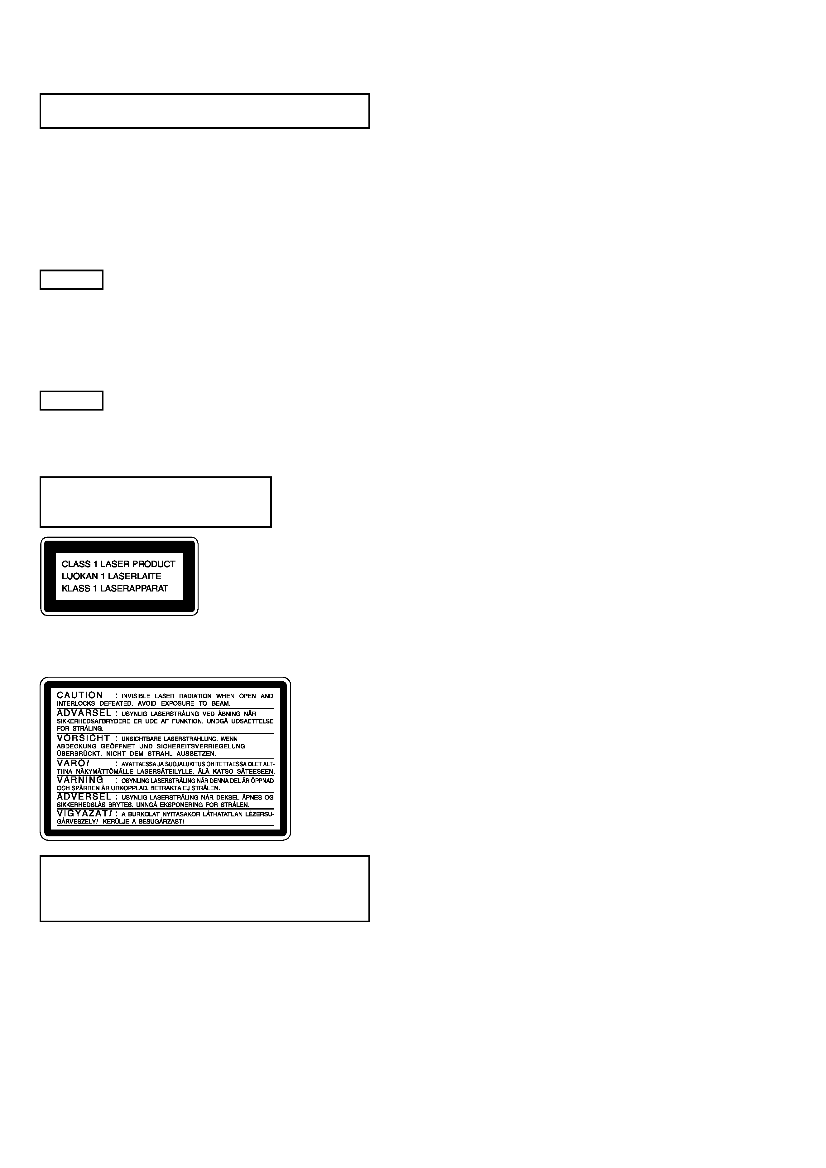
This appliance is classified as a CLASS 1 LASER product. The
CLASS 1 LASER PRODUCT MARKING is located on the bottom
exterior.
Laser component in this product is capable
of emitting radiation exceeding the limit for
Class 1.
CAUTION
Use of controls or adjustments or performance of procedures
other than those specified herein may result in hazardous radiation
exposure.
Notes on chip component replacement
· Never reuse a disconnected chip component.
· Notice that the minus side of a tantalum capacitor may be
damaged by heat.
Flexible Circuit Board Repairing
· Keep the temperature of soldering iron around 270°C
during repairing.
· Do not touch the soldering iron on the same conductor of the
circuit board (within 3 times).
· Be careful not to apply force on the conductor when soldering
or unsoldering.
NOTES ON HANDLING THE OPTICAL PICK-UP
BLOCK OR BASE UNIT
The laser diode in the optical pick-up block may suffer electrostatic
break-down because of the potential difference generated by the
charged electrostatic load, etc. on clothing and the human body.
During repair, pay attention to electrostatic break-down and also
use the procedure in the printed matter which is included in the
repair parts.
The flexible board is easily damaged and should be handled with
care.
FOR CD
NOTES ON LASER DIODE EMISSION CHECK
The laser beam on this model is concentrated so as to be focused on
the disc reflective surface by the objective lens in the optical pick-
up block. Therefore, when checking the laser diode emission,
observe from more than 30 cm away from the objective lens.
FOR MD
NOTES ON LASER DIODE EMISSION CHECK
Never look into the laser diode emission from right above when
checking it for adjustment. It is feared that you will lose your sight.
This caution
label is
located inside
the unit.
SAFETY-RELATED COMPONENT WARNING!!
COMPONENTS IDENTIFIED BY MARK 0 OR DOTTED LINE WITH
MARK 0 ON THE SCHEMATIC DIAGRAMS AND IN THE PARTS
LIST ARE CRITICAL TO SAFE OPERATION. REPLACE THESE
COMPONENTS WITH SONY PARTS WHOSE PART NUMBERS
APPEAR AS SHOWN IN THIS MANUAL OR IN SUPPLEMENTS
PUBLISHED BY SONY.