SERVICE MANUAL
Sony Corporation
Audio Group
Published by Sony Engineering Corporation
US Model
Canadian Model
COMPACT DISC PLAYER
9-879-248-01
2004K1678-1
© 2004.11
Ver. 1.0 2004.11
SPECIFICATIONS
CDP-C5CS
Model Name Using Similar Mechanism
CDP-CE375
CD Mechanism Type
CDM59-5BD27
Base Unit Name
BU-5BD27
Optical Pick-up Name
PXR-104X
General
Power requirements
120 V AC, 60 Hz
Power consumption
11 W
Dimensions (approx.)
430 x 110 x 400 mm
(w/h/d)
(17 x 4 3/8 x 15 3/4 in.)
incl. projecting parts
Mass (approx.)
5 kg (11 lbs 1 oz)
Supplied accessories
Audio cord (2 phono plugs 2 phono plugs) (1)
Remote commander (remote) (1)
R6 (size AA) batteries (2)
Design and specifications are subject to change
without notice.
Compact disc player
Laser
Semiconductor laser (
=
780 nm)
Emission duration:
continuous
Frequency response
2 Hz to 20 kHz
± 0.5 dB
Dynamic range
More than 93 dB
Harmonic distortion
Less than 0.0045%
Outputs
ANALOG
OUT
DIGITAL
OUT
(OPTICAL)
PHONES
Load
impedance
Over 10
kilohms
Wave
length:
660 nm
32 ohms
Jack
type
Phono
jacks
Optical
output
connector
Stereo
phone
jack
Maximum
output level
2 V
(at 50 kilohms)
18 dBm
10 mW
2
CDP-C5CS
SAFETY CHECK-OUT
After correcting the original service problem, perform the following
safety check before releasing the set to the customer:
Check the antenna terminals, metal trim, "metallized" knobs, screws,
and all other exposed metal parts for AC leakage.
Check leakage as described below.
LEAKAGE TEST
The AC leakage from any exposed metal part to earth ground and
from all exposed metal parts to any exposed metal part having a
return to chassis, must not exceed 0.5 mA (500 microamperes.).
Leakage current can be measured by any one of three methods.
1. A commercial leakage tester, such as the Simpson 229 or RCA
WT-540A. Follow the manufacturers' instructions to use these
instruments.
2. A battery-operated AC milliammeter. The Data Precision 245
digital multimeter is suitable for this job.
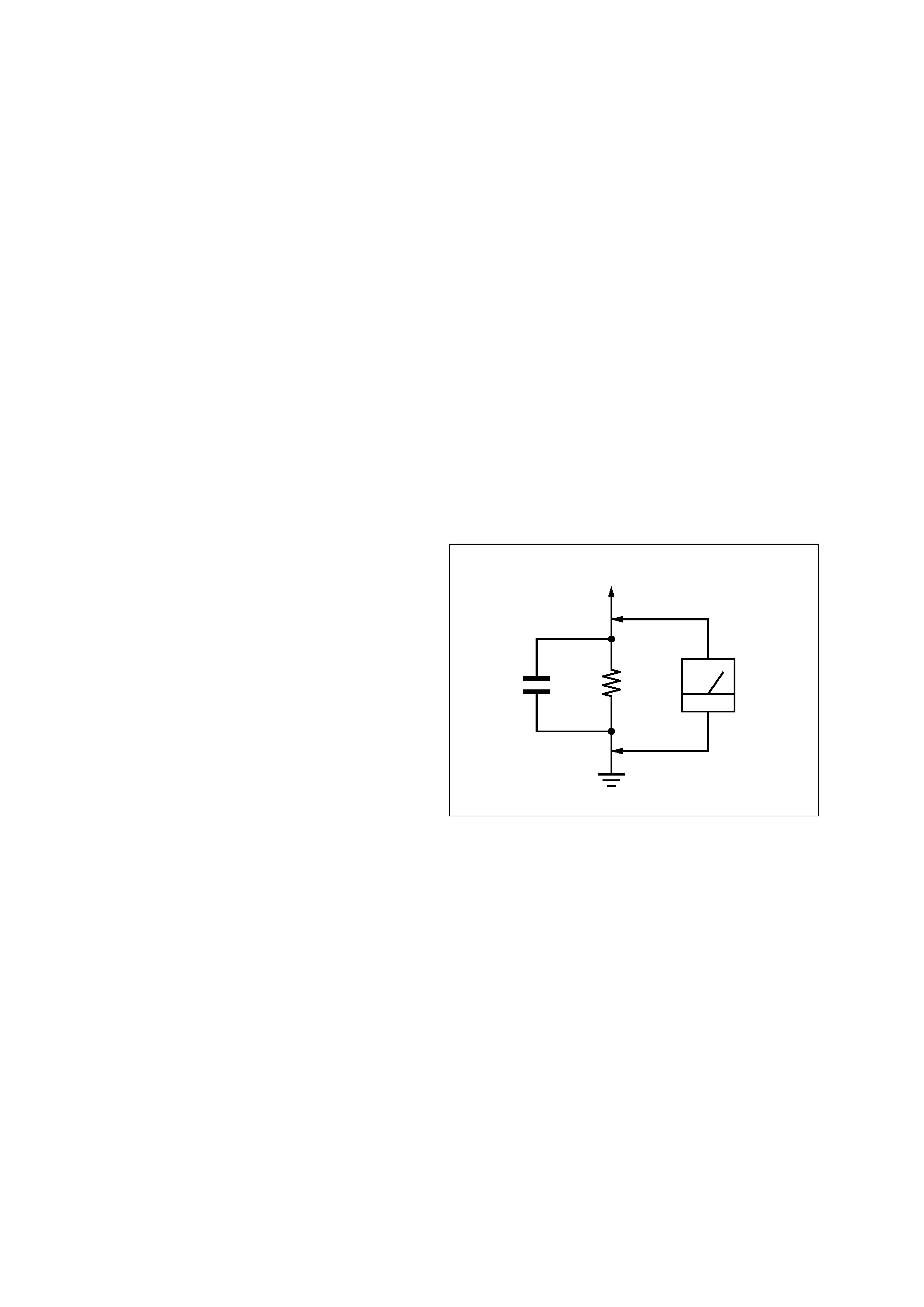
3. Measuring the voltage drop across a resistor by means of a
VOM or battery-operated AC voltmeter. The "limit" indication
is 0.75 V, so analog meters must have an accurate low-voltage
scale. The Simpson 250 and Sanwa SH-63Trd are examples
of a passive VOM that is suitable. Nearly all battery operated
digital multimeters that have a 2 V AC range are suitable. (See
Fig. A)
Fig. A.
Using an AC voltmeter to check AC leakage.
1.5 k
0.15
µF
AC
voltmeter
(0.75 V)
To Exposed Metal
Parts on Set
Earth Ground
SAFETY-RELATED COMPONENT WARNING!!
COMPONENTS IDENTIFIED BY MARK 0 OR DOTTED LINE
WITH MARK 0 ON THE SCHEMATIC DIAGRAMS AND IN
THE PARTS LIST ARE CRITICAL TO SAFE OPERATION.
REPLACE THESE COMPONENTS WITH SONY PARTS WHOSE
PART NUMBERS APPEAR AS SHOWN IN THIS MANUAL OR
IN SUPPLEMENTS PUBLISHED BY SONY.
ATTENTION AU COMPOSANT AYANT RAPPORT
À LA SÉCURITÉ!
LES COMPOSANTS IDENTIFIÉS PAR UNE MARQUE 0 SUR
LES DIAGRAMMES SCHÉMATIQUES ET LA LISTE DES
PIÈCES
SONT
CRITIQUES
POUR
LA
SÉCURITÉ
DE
FONCTIONNEMENT. NE REMPLACER CES COM- POSANTS
QUE PAR DES PIÈCES SONY DONT LES NUMÉROS SONT
DONNÉS DANS CE MANUEL OU DANS LES SUPPLÉMENTS
PUBLIÉS PAR SONY.
TABLE OF CONTENTS
1.
SERVICING NOTES ................................................ 3
2.
GENERAL ................................................................... 4
3.
DISASSEMBLY
3-1.
Disassembly Flow ...........................................................
5
3-2.
Case .................................................................................
6
3-3.
Front Panel Assy, IR-IN Board ........................................
6
3-4.
CD Mechanism Block (CDM59-5BD27) ........................
7
3-5.
Base Unit (BU-5BD27) ...................................................
7
3-6.
Tray, Table Assy ..............................................................
8
3-7.
SENSOR Board ...............................................................
8
3-8.
JUNCTION Board, LOADING MOTOR Board .............
9
3-9.
Optical Pick-up ................................................................
9
4.
TEST MODE ............................................................... 10
5.
ELECTRICAL ADJUSTMENT ............................. 13
6.
DIAGRAMS
6-1.
Block Diagram BD Section ....................................... 16
Display Section ......................................................... 17
6-2.
Printed Wiring Board BD Section ............................. 18
6-3.
Schematic Diagram BD Section ................................ 19
6-4.
Printed Wiring Board CDM59 COMB Section ......... 20
6-5.
Schematic Diagram CDM59 COMB Section ........... 21
6-6.
Printed Wiring Board MAIN Section ........................ 22
6-7.
Schematic Diagram MAIN Section ........................... 23
6-8.
Printed Wiring Board PANEL Section ...................... 24
6-9.
Schematic Diagram PANEL Section ......................... 25
7.
EXPLODED VIEWS
7-1.
Case Section .................................................................... 30
7-2.
Front Panel Section ......................................................... 31
7-3.
CD Mechanism Section (1) (CDM59-5BD27) ............... 32
7-4.
CD Mechanism Section (2) (CDM59-5BD27) ............... 33
7-5.
Base Unit Section (BU-5BD27) ...................................... 34
8.
ELECTRICAL PARTS LIST .................................. 35
3
CDP-C5CS
SECTION 1
SERVICING NOTES
Notes on chip component replacement
· Never reuse a disconnected chip component.
· Notice that the minus side of a tantalum capacitor may be
damaged by heat.
Flexible Circuit Board Repairing
· Keep the temperature of the soldering iron around 270 °C
during repairing.
· Do not touch the soldering iron on the same conductor of the
circuit board (within 3 times).
· Be careful not to apply force on the conductor when soldering
or unsoldering.
LASER DIODE AND FOCUS SEARCH OPERATION
CHECK
Carry out the "S curve check" in "CD section adjustment" and check
that the S curve waveforms is output three times.
CAUTION
Use of controls or adjustments or performance of procedures
other than those specified herein may result in hazardous radiation
exposure.
This appliance is classified as a CLASS 1 LASER product.
The CLASS 1 LASER PRODUCT MARKING is located on the
rear exterior.
The laser diode in the optical pick-up block may suffer electrostatic
break-down because of the potential difference generated by the
charged electrostatic load, etc. on clothing and the human body.
During repair, pay attention to electrostatic break-down and also
use the procedure in the printed matter which is included in the
repair parts.
The flexible board is easily damaged and should be handled with
care.
NOTES ON LASER DIODE EMISSION CHECK
The laser beam on this model is concentrated so as to be focused on
the disc reflective surface by the objective lens in the optical pick-
up block. Therefore, when checking the laser diode emission,
observe from more than 30 cm away from the objective lens.
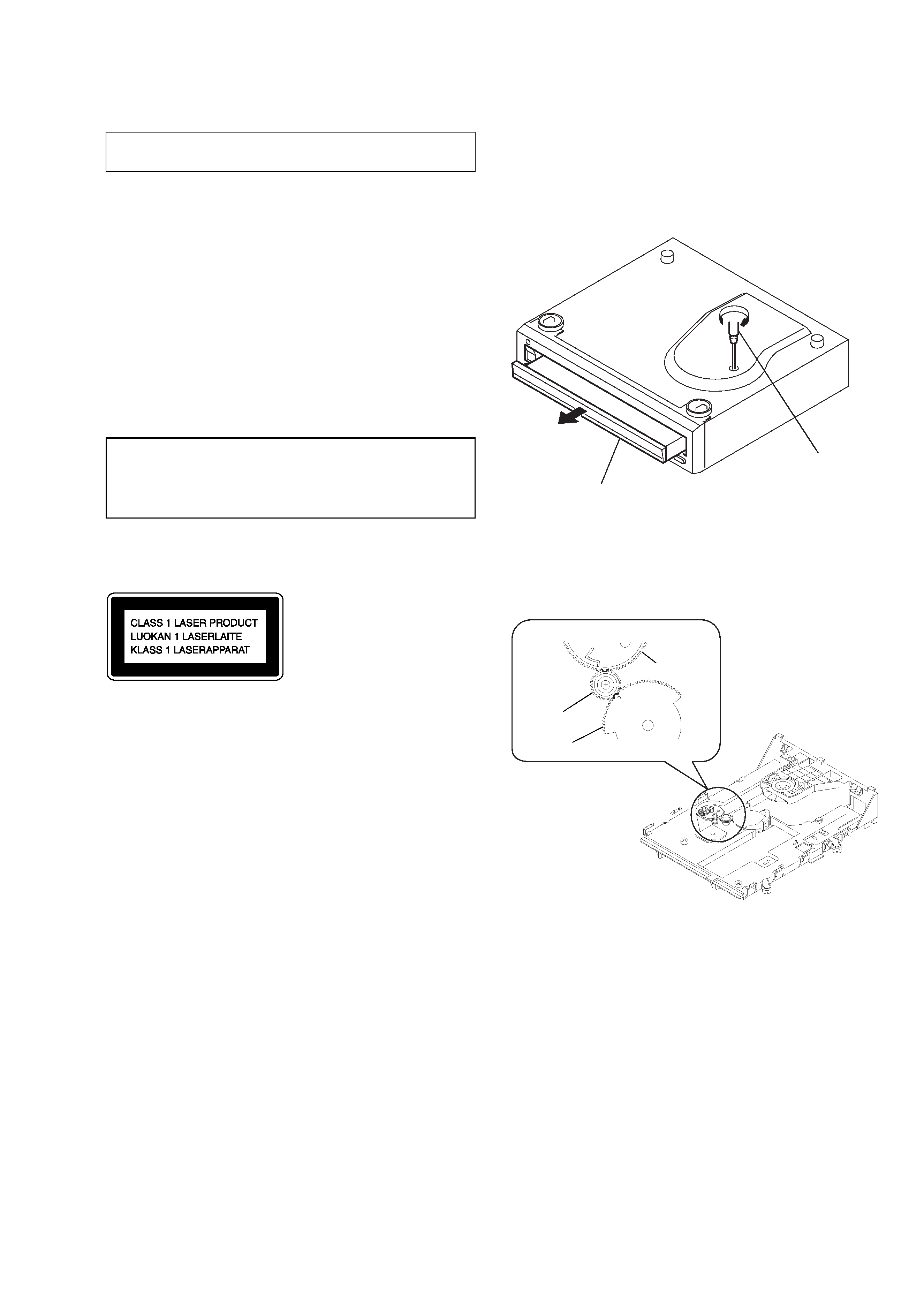
NOTES ON HANDLING THE OPTICAL PICK-UP
BLOCK OR BASE UNIT
HOW TO OPEN THE DISC TABLE WHEN POWER
SWITCH TURNS OFF
Insert a tapering driver into the aperture of the unit bottom, and turn
it in the direction of the arrow (to OUT direction).
NOTE FOR MAIN GEAR INSTALLATION
table
tapering driver
* To close the disc table, turn the tapering
driver in the reverse direction (to IN direction).
gear (U/D)
gear (RV)
gear, swing
4
CDP-C5CS
SECTION 2
GENERAL
This section is extracted
from instruction manual.
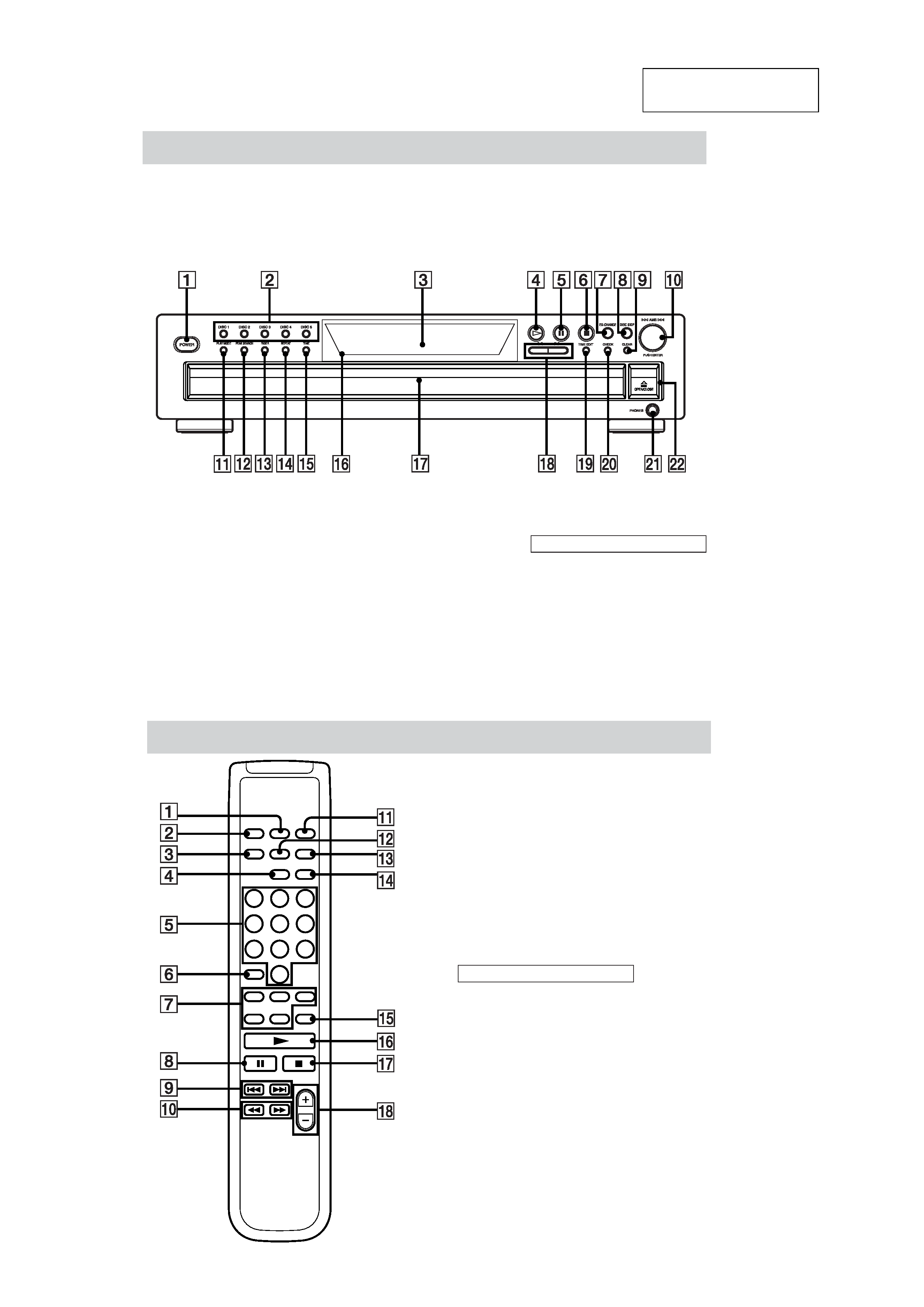
Front Panel
The items are arranged in alphabetical order.
Refer to the pages indicated in parentheses ( ) for details.
CDP-C5CS
CHECK w; (11, 12)
CLEAR 9 (11, 12)
DISC 15 2 (7, 8, 11)
Disc compartment qj (7)
DISC SKIP 8 (7, 10, 12)
Display 3 (9)
EX-CHANGE 7 (10, 13)
FADER qd (12)
PEAK SEARCH qs (13)
PHONES jack wa (8)
PLAY MODE qa (8, 11, 13)
POWER 1 (7)
Remote sensor qh (6)
REPEAT qf (8)
TIME qg (9, 10)
TIME EDIT ql (12)
BUTTON DESCRIPTIONS
A OPEN/CLOSE ws (6, 7, 8, 9)
H 4 (7, 8, 11, 13)
X 5 (8, 13)
x 6 (8, 13)
lAMSL dial 0 (8, 9, 11,
13)
m/M qk (8, 9, 12)
Remote Control
ANALOG OUT LEVEL +/ qk (8, 9)
CHECK qs (11, 12)
CLEAR qd (11, 12)
CONTINUE 2 (7)
DISC 15 7 (7, 8, 11)
DISC SKIP qg (7, 10, 12)
FADER qf (12)
Number buttons 5 (8, 11)
PROGRAM qa (7)
REPEAT 3 (8)
SHUFFLE 1 (7)
TIME 4 (9, 10)
BUTTON DESCRIPTIONS
>10 6 (8)
N qh (8, 11, 13)
X 8 (8, 13)
x qj (8, 13)
. AMS > 9 (8, 9, 11, 13)
m/M 0 (8, 9, 12)
5
CDP-C5CS
SECTION 3
DISASSEMBLY
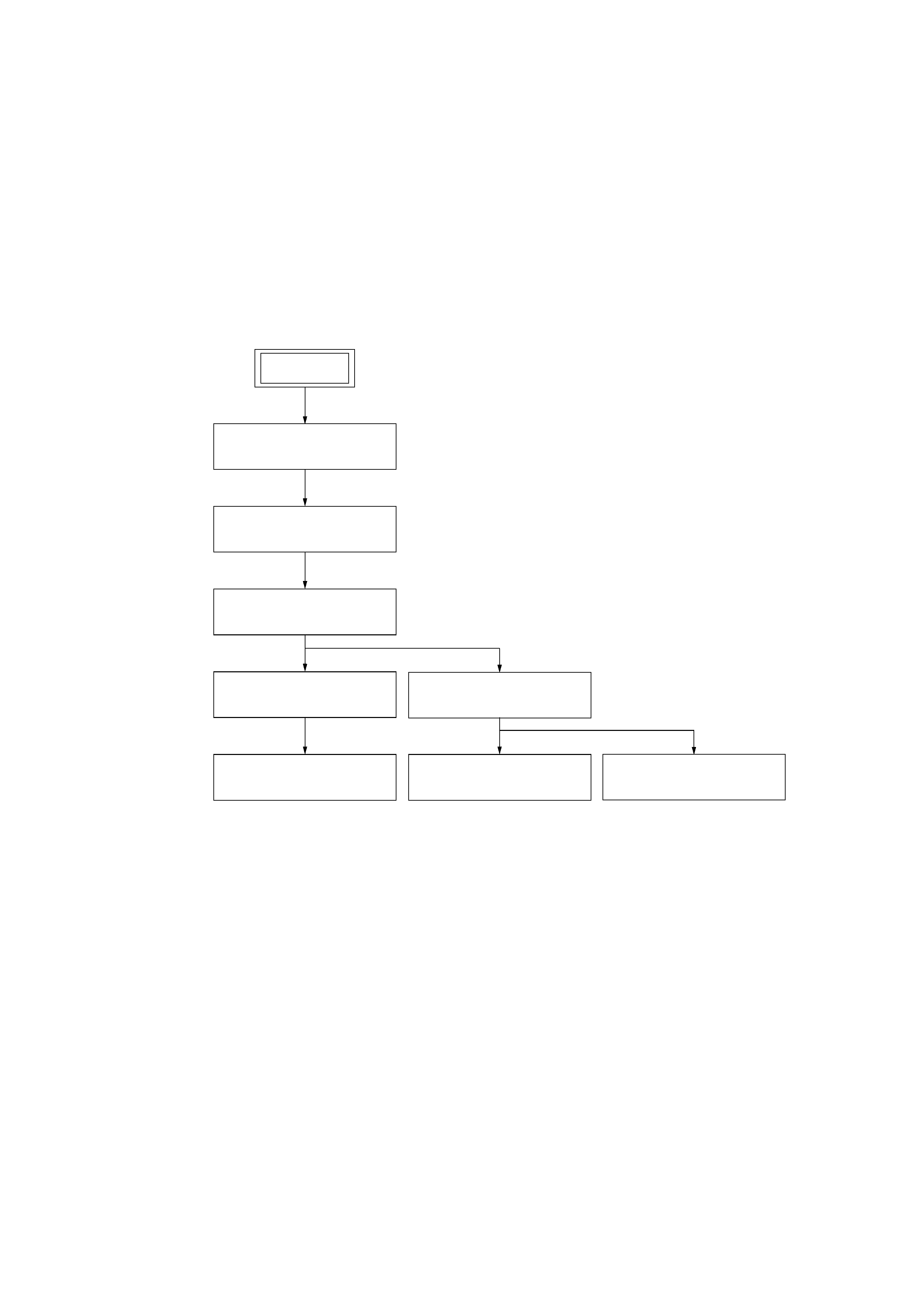
3-1. DISASSEMBLY FLOW
·The equipment can be removed using the following procedure.
3-3.FRONT PANEL ASSY,
IR-IN BOARD
(Page 6)
3-4.CD MECHANISM BLOCK
(CDM59-5BD27)
(Page 7)
3-5.BASE UNIT (BU-5BD27)
(Page 7)
3-9.OPTICAL PICK-UP
(Page 9)
3-7.SENSOR BOARD
(Page 8)
3-6.TRAY ,TABLE ASSY
(Page 8)
3-8.JUNCTION BOARD,
LOADING MOTOR BOARD
(Page 9)
3-2.CASE
(Page 6)
SET