ORDER NO.
PIONEER CORPORATION 4-1, Meguro 1-chome, Meguro-ku, Tokyo 153-8654, Japan
PIONEER ELECTRONICS (USA) INC. P.O. Box 1760, Long Beach, CA 90801-1760, U.S.A.
PIONEER EUROPE NV Haven 1087, Keetberglaan 1, 9120 Melsele, Belgium
PIONEER ELECTRONICS ASIACENTRE PTE. LTD. 253 Alexandra Road, #04-01, Singapore 159936
PIONEER CORPORATION 2007
RRV3547
T ZZA JAN. 2007 Printed in Japan
SPEAKER SYSTEM
S-VSL4
XCN5
S-VSL4
1. REASSEMBLY AND DISASSEMBLY PRECAUTIONS
Port tube
Network Assy
The grille is attached to the cabinet by its bosses applied with
adhesive. To detach it, first unfasten 4 screws of the top plate.
Next detach the top plate with the packing. Then pry it open by
inserting a flat blade screwdriver into the grille upper side. To
attach it, first attach the top plate and packing by 4 screws. Next
apply adhesive to the holes on the baffle. Then press it to the
baffle.
The cosmetic grille is attached to the cabinet by packing with
double-faced adhesive tape and catches. To detach it, first re-
move the grille. Then pry it open by inserting a flat blade screw-
driver into upper side. To re-attach it, adjust the catch of the
cosmetic grille to the baffle board. Then press it to the cabinet.
The woofer is attached to the baffle by 4 external screws. To
detach it, unfasten those screws and turn it 45 degrees counter-
clockwise. When attaching it, face its terminal upward.
The tweeter is attached to the baffle by 3 external screws. To
detach it, unfasten those screws. When attaching it, face its ter-
minal downward.
Network ASSY is attached to the cabinet as shown in the left
figure. The network assy is attached to the baffle by 4 internal
screws. To detach it, unfasten those screws. To detach it, re-
move the grille. Then detach the baffle board (18 screws). To
attaching it, fit its hole into the hollow on the baffle.
Choke coil face downward
2
1
23
4
12
3
4
C
D
F
A
B
E
S-VSL4
17
13
14
12
15
16
5
5
2
11
9
5
5
1
7
1
2
3
6
1
4
2
5
3
6
10
3
8
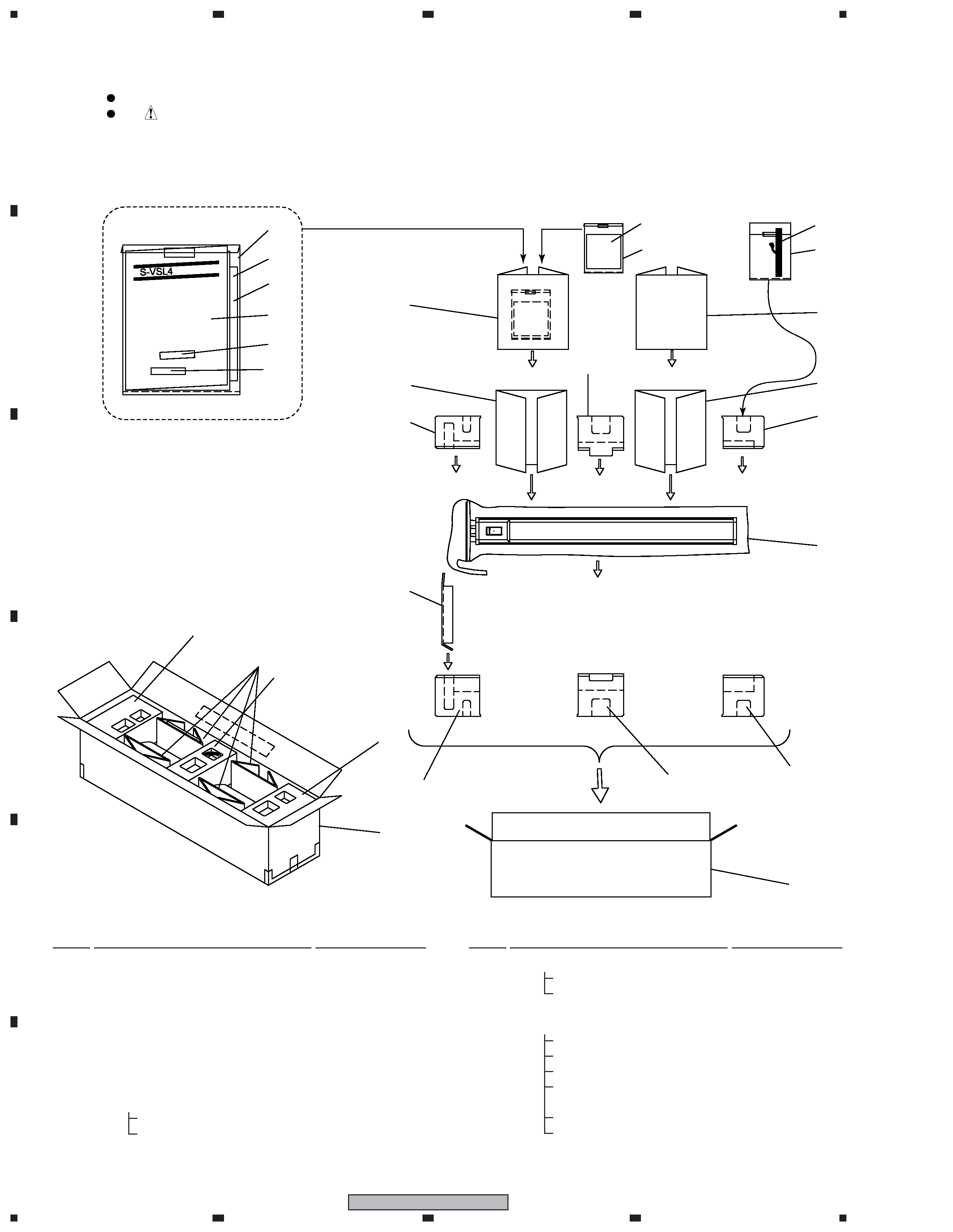
PACKING Parts List
2.1 PACKING
Mark No.
Description
Part No.
Mark No.
Description
Part No.
1
Protector (Top)
SHA2392
2
Protector (Middle)
SHA2393
3
Protector (Bottom)
SHA2394
4
Protector (for side 4 places)
SHB1138
5
Protector (for Base)
SHB6042
6
Packing Case
SHG6247
7
Polyethylene Bag
SHL6069
NSP
Accessory Set
· · · · · ·
8
Speaker Wire
SDS1106
9
Polyethylene Bag
SHL1252
2. EXPLODED VIEWS AND PARTS LIST
Parts marked by "NSP" are generally unavailable because they are not in our Master Spare Parts List.
The
mark found on some component parts indicates the importance of the safety factor of the part.
Therefore, when replacing, be sure to use parts of identical designation.
NOTES:
NSP
Accessory Set
· · · · · ·
10
Acoustic Absorbent
SMT1208
11
Polyethylene Bag
SHL1295
NSP
Accessory Set
· · · · · ·
12
Owner's Manual
SRD6068
13
Green e-Mark Manual
SRD6076
NSP
14
Warranty Card
· · · · · ·
15
Velcro (Hook)
SER1334
16
Velcro (Loop)
SER1335
17
Polyethylene Bag
SHL6010
3
1
23
4
1
2
3
4
C
D
F
A
B
E
S-VSL4
A view
A view
2
Top Plate
Front Plate
13 (x 18)
11
14 (x 11)
10
3
1
4
15 (x 4)
5
6
Base
Bttom Plate
17 (x 8)
12
7
Model Label
16 (x 3)
16 (x 3)
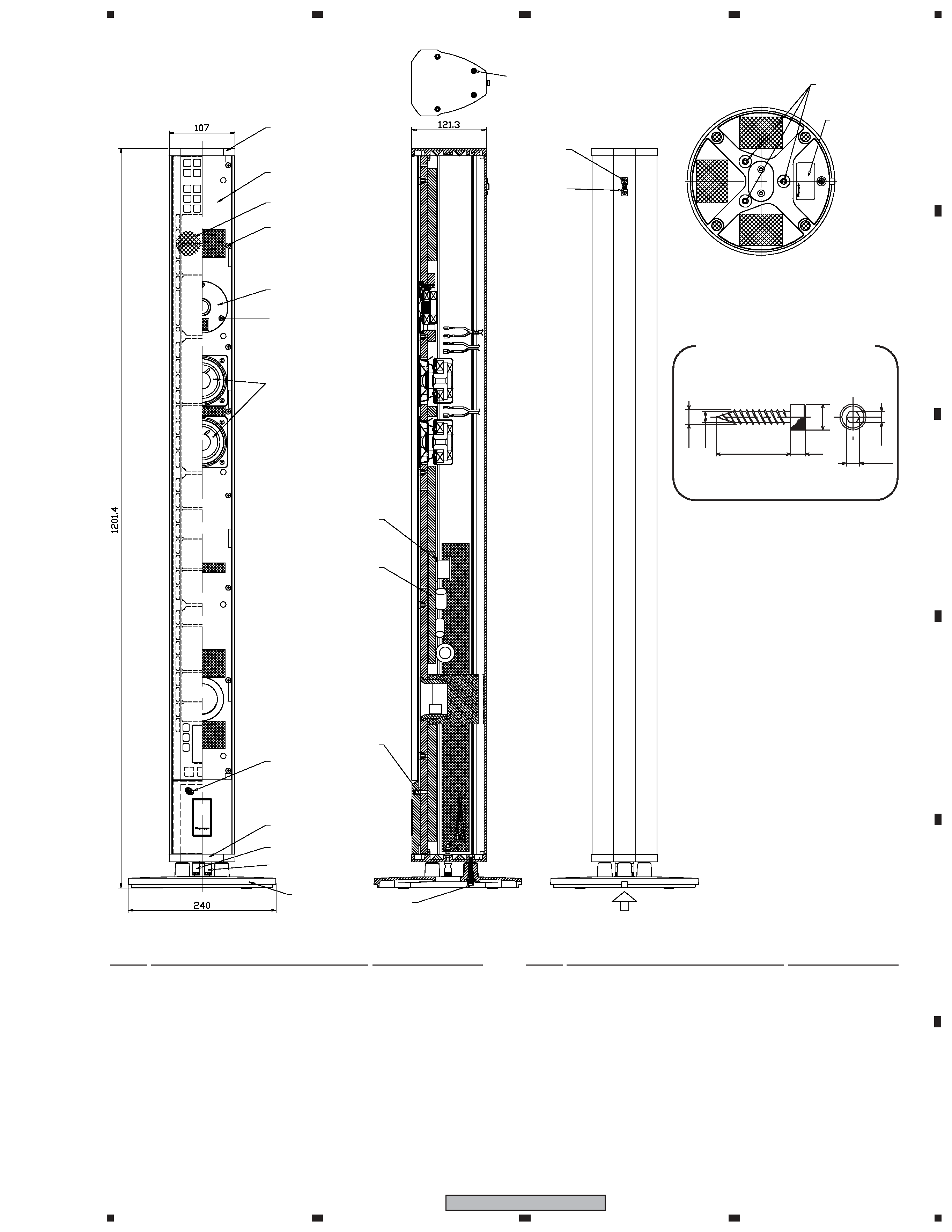
Mark No.
Description
Part No.
SPEAKER SYSTEM Parts List
1
Catch
SLH1072
2Grille Ass'y
SMG6118
3
Cosmetic Grille
SMG6119
4
Network Assy
SWN6023
5
Input Terminal (Red)
SKX1087
6
Input Terminal (Black)
SKX1088
7
Fastener
SNB1068
8
Non Skid Pad (for Tw damping)
SEC1547
9Non Skid Pad (for Base)
SEB1257
10
Speaker (Wf)
K77ER65-53H
Mark No.
Description
Part No.
11
Speaker (Tw)
FADD55-56D
12
Screw (for Fastener)
BMZ30P050FNC
13
Screw (for Baffle Board)
SBA6013
14
Screw (for Wf/Tw)
SBA1259
15
Screw (for Nw Assy)
BYC40P200FTB
16
Screw (for Base)
SBA6046
17
Screw (for Top Plate/Bottom Plate) SYZ40H200FCR
2.2 SPEAKER SYSTEM
3
(3.6)
7
4
3
4
20
Screw (SBA1259)
4
1
23
4
12
3
4
C
D
F
A
B
E
S-VSL4
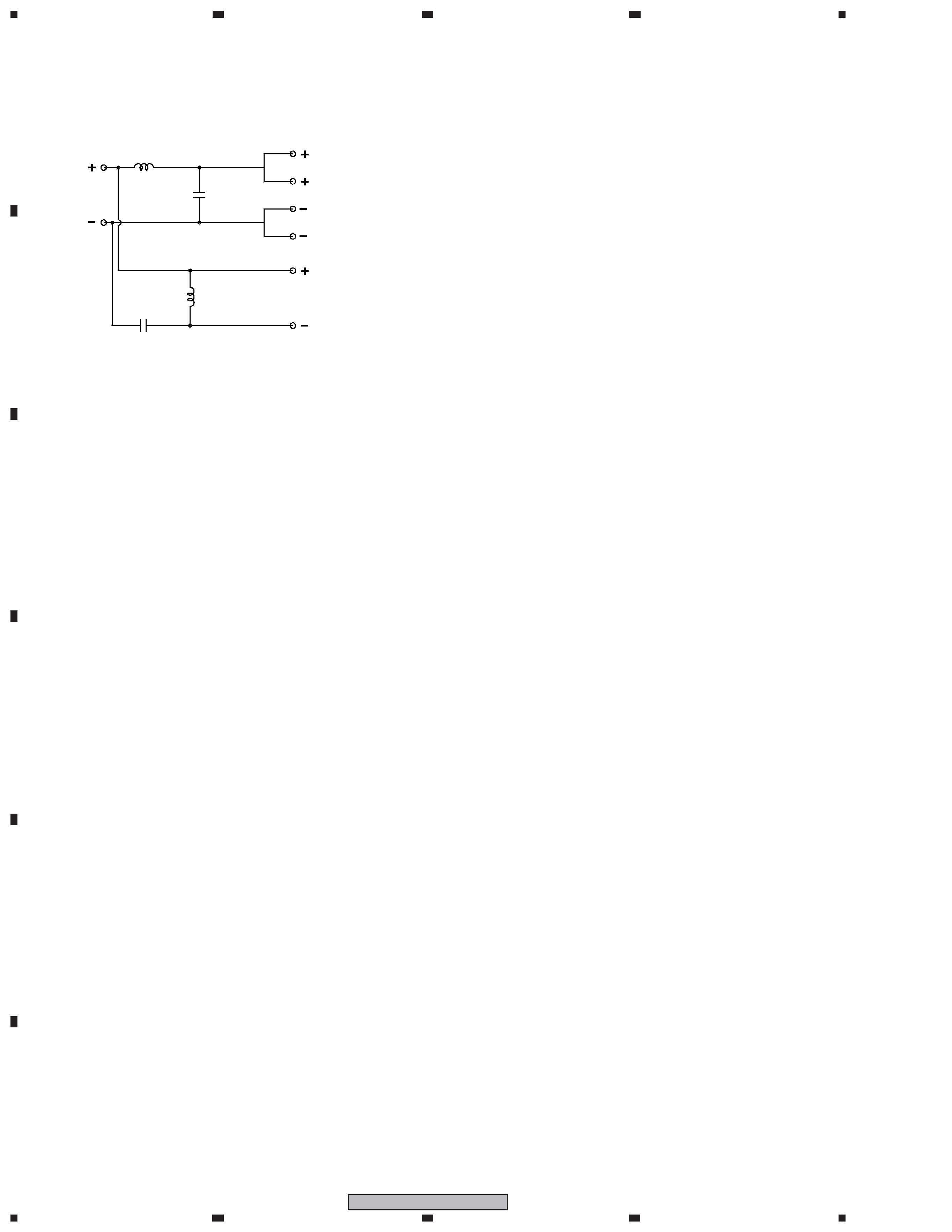
3. SCHEMATIC DIAGRAM
e.
s.
e.
s.
L1
C1
C2
L2
Woofer
I NPUT
Tweeter
3.3
µF
2.7
µF
0.7 mH
0.3 mH
NETWORK ASSY (SWN6023)