ORDER NO.
PIONEER CORPORATION 4-1, Meguro 1-chome, Meguro-ku, Tokyo 153-8654, Japan
PIONEER ELECTRONICS (USA) INC. P.O. Box 1760, Long Beach, CA 90801-1760, U.S.A.
PIONEER EUROPE NV Haven 1087, Keetberglaan 1, 9120 Melsele, Belgium
PIONEER ELECTRONICS ASIACENTRE PTE. LTD. 253 Alexandra Road, #04-01, Singapore 159936
PIONEER CORPORATION 2005
RRV3152
T ZZK MAY 2005 Printed in Japan
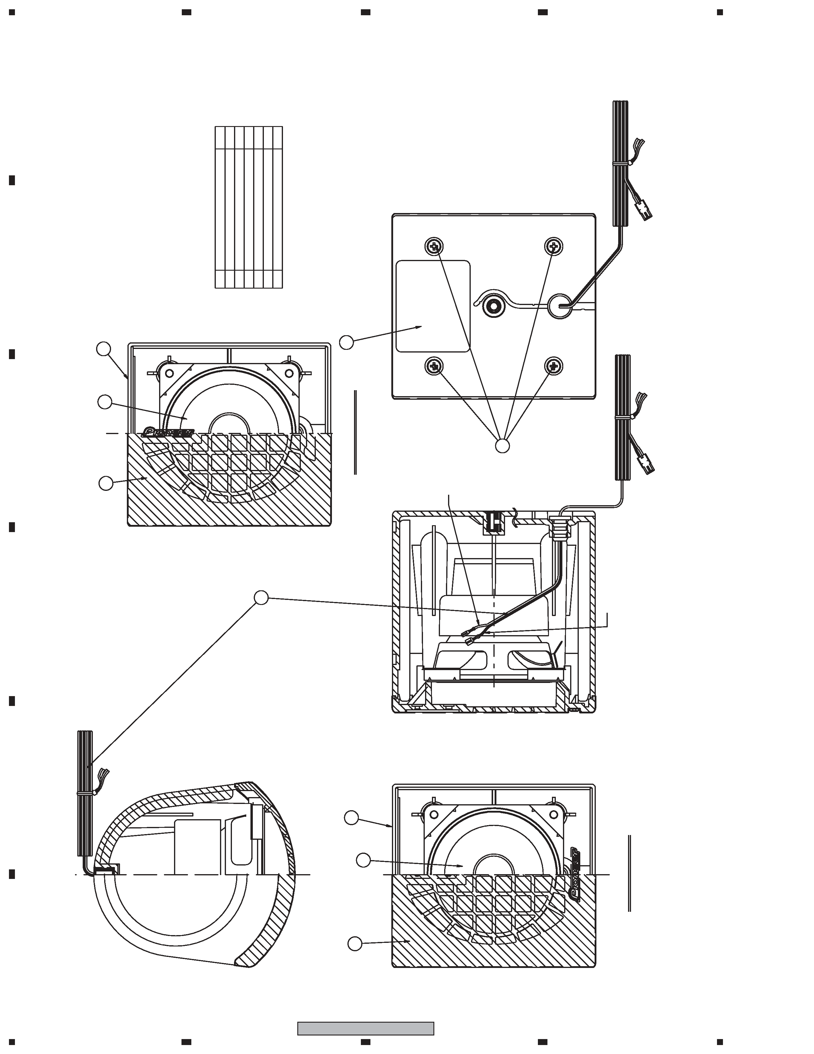
FOR PRECAUTION OF
REASSEMBLY AND DISASSEMBLY
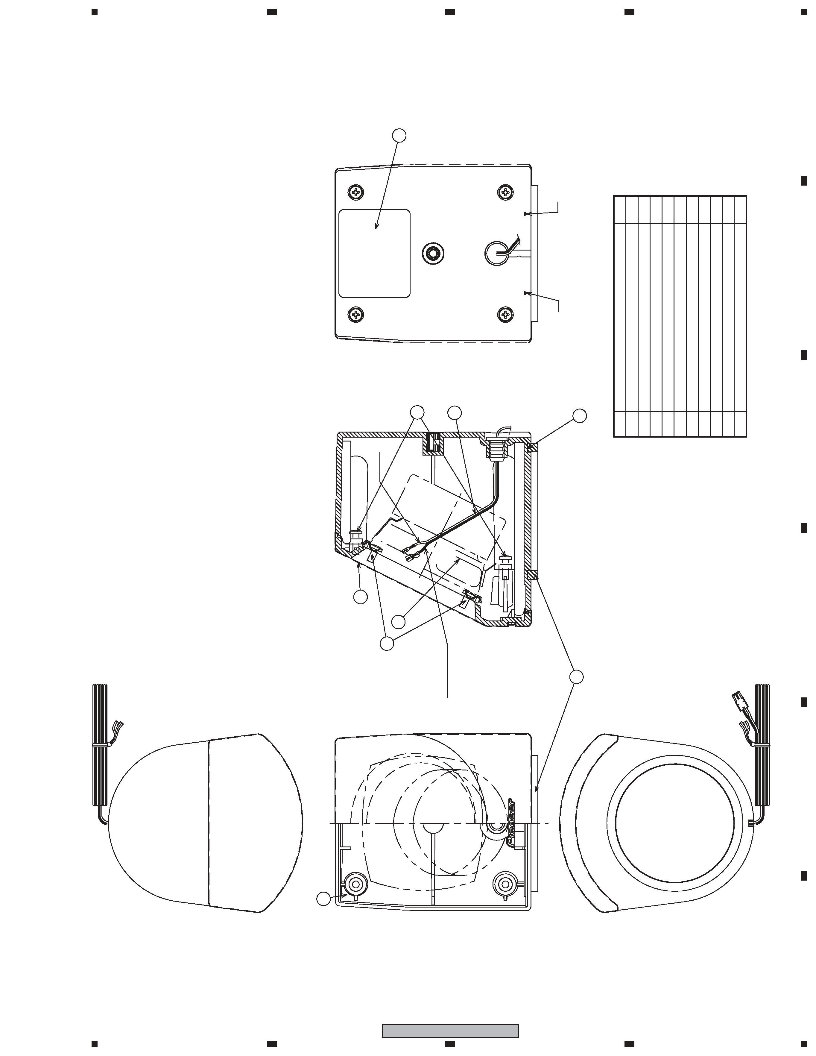
CS Assy ( Subwoofer )
The speaker unit is attached to the rear baffle by 4 external
screws. To detach it, unfasten those screws.
When attaching it, face its terminal rightward.
CS Assy ( Front )
The grille assy is attached to the cabinet by 4 external screws.
To detach it, unfasten those screws.
The speaker unit, together with the Grille, is attached to the
cabinet by 4 external screws.
To detach it, first unfasten those screws. Next remove the cabi-
net. Then remove the cable.
When attaching it, face its terminal downward.
CS Assy ( Center )
The grille assy is attached to the cabinet by 4 external screws.
To detach it, unfasten those screws.
The speaker unit, together with the Grille, is attached to the
cabinet by 4 external screws.
To detach it, first unfasten those screws. Next remove the cabi-
net. Then remove the cable.
When attaching it, face its terminal rightward.
CS Assy ( Surround )
The grille assy is attached to the cabinet by 4 screws. To detach
it, unfasten those screws.
The speaker unit is attached to the Grille by 4 internal screws.
To detach it, first unfasten those screws. Next remove the cable.
When attaching it, face its terminal downward.
SPEAKER SYSTEM
S-DV131
XJC/E
S-DV131 XJC/NC
Sub Woofer
Center
Surround
Front
2
1
23
4
12
3
4
C
D
F
A
B
E
S-DV131
For Packing
Parts marked by "NSP" are generally unavailable because they are not in our Master Spare Parts List.
The
mark found on some component parts indicates the importance of the safety factor of the part.
Therefore, when replacing, be sure to use parts of identical designation.
NOTES:
PARTS LIST
Mark No.
Description
Part No.
CS ASSY (Front)
Mark No.
Description
Part No.
NSP
Cabinet
SNK2840
Grille
SMG1835
NSP
Badge 28
SAM1506
NSP
Grille Cloth
SAS1588
NSP
Baffle
SNK2843
Speaker Wire (Plug: White)
SDD1334
Speaker Wire (Plug: Red)
SDD1335
Speaker
K77DC55-52D
Screw (for Cabinet)
BPZ35P120FNI
NSP
CS Assy (Front)
SMW1857
NSP
CS Assy (Center)
SMW1864
NSP
CS Assy (Surround)
SMW1858
NSP
CS Assy (Subwoofer)
SMW1859
for XJC/E type
NSP
Model Label (FL)
SAN3632
NSP
Model Label (FR)
SAN3633
NSP
Model Label (SL)
SAN3634
NSP
Model Label (SR)
SAN3635
NSP
Model Label (C)
SAN3536
NSP
Model Label (SW)
SAN3537
for XJC/NC type
NSP
Model Label (FL)
SAN3638
NSP
Model Label (FR)
SAN3639
NSP
Model Label (SL)
SAN3640
NSP
Model Label (SR)
SAN3641
NSP
Model Label (C)
SAN3542
NSP
Model Label (SW)
SAN3543
NSP
Accessory Set
SEA1683
NSP
Screw Set
SEA1676
Screw
BMZ50P120FNC
Polyethylene Bag S0
SHL1314
Non Skid Pad
SEC1912
Non Skid Pad
SEP6002
Mounting Bracket
SNN1047
Poly Bag S1
SHL1429
Top Protector
SHA2478
Middle Protector
SHA2479
Bottom Protector
SHA2480
Protection Sheet
SHC1821
Polyethylene Bag S2
SHL1417
for XJC/E type
Packing Case
SEC2640
for XJC/NC type
Packing Case
SEC2641
Mark No.
Description
Part No.
CS ASSY (Surround)
NSP
Cabinet (L)
SNK2841
NSP
Cabinet (R)
SNK2880
Grille
SMG1836
NSP
Badge 28
SAM1506
NSP
Grille Cloth
SAS1589
NSP
Baffle
SNK2844
Speaker Wire (Plug: Blue)
SDD1336
Speaker Wire (Plug: Gray)
SDD1337
Gasket
SEC1910
Speaker
K77DC55-51D
Screw (for Speaker)
BPZ35P080FNI
Screw (for Cabinet)
BPZ35P120FNI
3
1
23
4
1
2
3
4
C
D
F
A
B
E
S-DV131
Mark No.
Description
Part No.
CS ASSY (Subwoofer)
Mark No.
Description
Part No.
CS ASSY (Center)
NSP
Cabinet
SNK2840
Grille
SMG1837
NSP
Badge 28
SAM1506
NSP
Grille Cloth
SAS1588
NSP
Baffle
SMK2843
Speaker Wire (Plug: Green)
SDD1338
Speaker
K77DC55-52D
Screw (for Cabinet)
BPZ35P120FNI
NSP
Cabinet
SMM2012
Cosmetic Baffle Assy
SXB1474
NSP
Badge 37
SAM1507
Damper
SEP1305
NSP
Cosmetic Baffle
SNK2842
Packing
SEC1911
Gasket
SEC6058
Speaker Wire (Plug: Purple)
SDD1339
Speaker
A14LU75-53D
Screw (for Speaker)
BYC40P130FTB
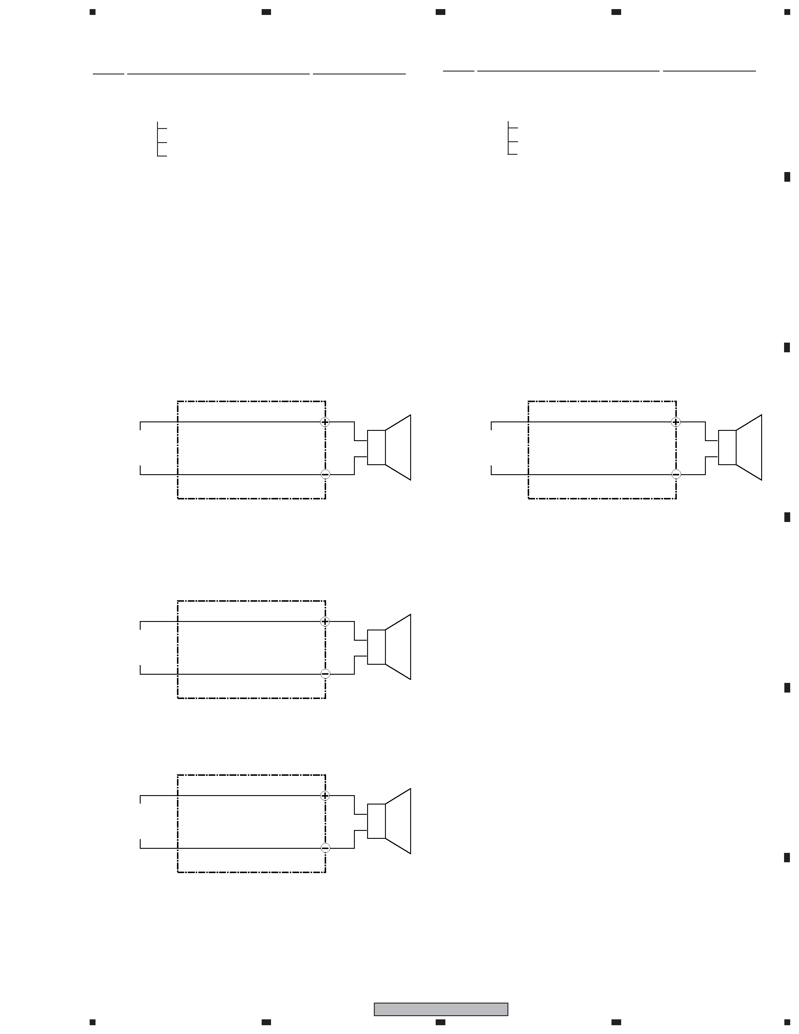
SCHEMATIC DIAGRAM
4, CS assy ( Subwoofer )
3, CS assy ( Center )
White with Gray Line
White
Speaker
INPUT PLUG
( Green )
Connecting Cord (SDD1338)
White with Gray Line
White
Speaker
INPUT PLUG
( Purple )
Connecting Cord (SDD1339)
White with Gray Line
White
Speaker
INPUT PLUG
PLUG color
SDD1334: White
SDD1335: Red
White with Gray Line
White
Speaker
INPUT PLUG
1, CS assy ( Front )
Connecting Cord (SDD1334, SDD1335)
2, CS assy ( Surround )
Connecting Cord (SDD1336, SDD1337)
PLUG color
SDD1336: Blue
SDD1337: Gray
4
1
23
4
12
3
4
C
D
F
A
B
E
S-DV131
PRODUCT APPEARANCE
CS ASSY ( Front and Center )
Screw
(M3.5x12)
Speaker
1
1
1
Part
Name
No.
Num.
Cabinet
Grille
Assy
Model
Label
Connecting
Cord
1
2
3
4
5
6
1
1
4
CENTER
SP
Front
FRONT
SP
Front
WHITE
WITH
GRA
Y
LINE
WHITE
1
1
2
2
3
3
4
5
6
5
1
23
4
1
2
3
4
C
D
F
A
B
E
S-DV131
PRODUCT APPEARANCE
CS ASSY ( Surround )
6
ONLY
SURROUND-R
ONLY
SURROUND-L
2
3
7
9
8
White
White
with
Gray
Line
4
5
Num.
No.
Part
Name
Cabinet
1
1
4
1
1
Connecting
Cord
Speaker
1
1
4
Screw
(M3.5x8)
Screw
(M3.5x12)
Grille
Assy
Model
Label
Glue
(ZBA-5119)
1
2
3
4
5
6
7
8
9
10
Gasket
1