
ENGLISH
ESPAÑOL
PORTUGUÊS
(B)
ITALIANO
NEDERLANDS
êìëëäàâ
BRIDGEABLE TWO-CHANNEL
POWER AMPLIFIER
Owner's Manual
PRS-D2200T
WOÐdFë

1
Before Using This Product ...................... 1
In case of trouble .............................................. 1
CAUTION ........................................................ 1
Visit our website ................................................ 1
CAUTION ........................................................ 2
WARNING ........................................................2
Setting the Unit .......................................... 3
Power Indicator ................................................ 3
Top Cover .......................................................... 3
Bass Boost Control ............................................ 3
BFC (Beat Frequency Control) Switch .................... 3
Cut Off Frequency Control .............................. 4
LPF (Low-Pass Filter)/HPF (High-Pass Filter)
Select Switch .............................................. 4
Gain Control ...................................................... 4
Input Switch ...................................................... 4
Setting the Gain properly .................................. 5
Connecting the Unit .................................. 6
Connection Diagram ........................................ 7
Solderless Terminal Connections ...................... 8
Connecting the Power Terminal ........................ 8
Connecting the Speaker Output Terminals ...... 9
Using the Speaker Input .................................... 9
Connecting the Speaker Wires ........................ 10
Installation ................................................ 11
Attaching the Bass boost remote control ........ 11
Example of installation on the floor mat
or on the chassis ...................................... 12
Replacing the top cover .................................. 12
Specifications .......................................... 13
Thank you for purchasing this PIONEER
product. Before attempting operation, be
sure to read this manual.
In case of trouble
When the unit does not operate properly,
contact your dealer or the nearest autho-
rized PIONEER Service Station.
CAUTION
·
Never replace the fuse with one of greater
value or rating than the original fuse. Use of
an improper fuse could result in overheating
and smoke and could cause damage to the
product and injury including burns.
·
Use the supplied hexagonal wrench to tight-
en screws when fastening wires to the termi-
nal. The use of a long, commercially avail-
able hexagonal wrench can cause excessive
torque to be applied possibly resulting in
damage to terminals and wires.
Visit our website
Visit us at the following site:
http://pioneer.jp/group/index-e.html
·We offer the latest information about
Pioneer Corporation on our website.
Contents
Before Using This Product
ENGLISH
ESPAÑOL
DEUTSCH
FRANÇAIS
ITALIANO
NEDERLANDS
êìëëäàâ
2
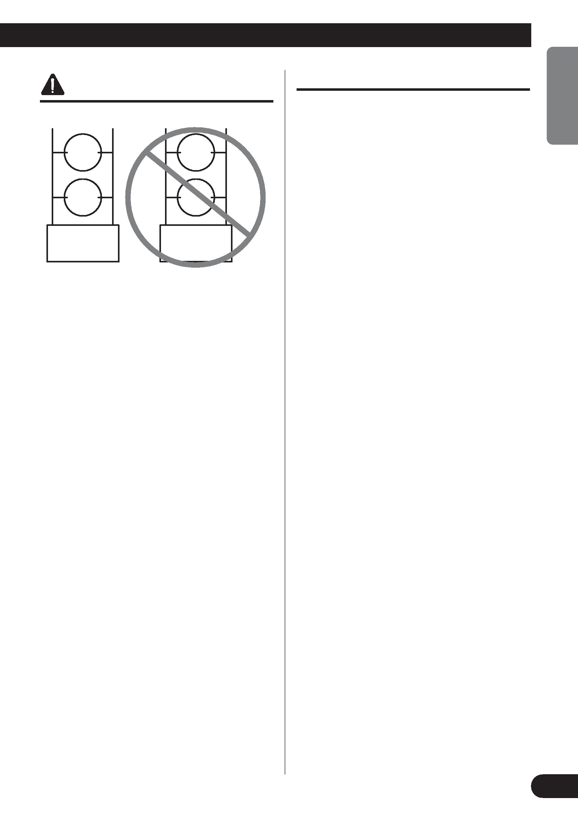
CAUTION
Do NOT install or use your Pioneer ampli-
fier by wiring speakers rated at 4 Ohm (or
lower) in parallel to achieve a 2 Ohm (or
lower) bridged mode (Diagram B).
Amplifier damage, smoke, and overheat-
ing could result from improper bridging.
The amplifier surface could also become
hot to the touch and minor burns could
result.
To properly install or use a bridged mode
for a two-channel amplifier and achieve a
4
load, wire two 8 speakers in paral-
lel with Left + and Right (Diagram A) or
use a single 4
speaker. For a four-chan-
nel amplifier, follow the speaker output
connection diagram for bridging as shown
on the back of your amplifier, and wire
two 8
speakers in parallel to achieve a 4
load or use a single 4 speaker per
channel.
If you have any questions or concerns,
please contact your local authorized
Pioneer dealer or call Pioneer customer
service.
WARNING
·We recommend that you use the special red bat-
tery and ground wire [RD-228], which is sold
separately. Connect the battery wire directly to
the car battery positive terminal (+) and the
ground wire to the car body.
·Do not touch the amplifier with wet hands.
Otherwise you may get an electric shock. Also,
do not touch the amplifier when it is wet.
· For traffic safety and to maintain safe driving
conditions, keep the volume low enough so that
you can still hear normal traffic sound.
· Check the connections of the power supply and
speakers if the fuse of the separately sold battery
wire or the amplifier fuse blows. Detect the cause
and solve the problem, then replace the fuse with
another one of the same size and rating.
· To prevent malfunction of the amplifier and
speakers, the protective circuit will cut the power
supply to the amplifier (sound will stop) when an
abnormal condition occurs. In such a case, switch
the power to the system OFF and check the
connection of the power supply and speakers.
Detect the cause and solve the problem.
·Contact the dealer if you cannot detect the cause.
· To prevent an electric shock or short-circuit
during connection and installation, be sure to
disconnect the negative () terminal of the battery
beforehand.
·Confirm that no parts are behind the panel when
drilling a hole for installation of the amplifier. Be
sure to protect all cables and important equipment
such as fuel lines, brake lines and the electrical
wiring from damage.
· DO NOT allow amplifier to come into contact
with liquids due to, for example, the location
where the amplifier is installed. Electrical shock
could result. Also, amplifier and speaker damage,
smoke, and overheating could result from contact
with liquids. In addition, the amplifier surface
and the surface of any attached speakers could
become hot to the touch and minor burns could
result.
Diagram A - Proper
8
Ohm
Speaker
+
-
8
Ohm
Speaker
Pioneer
Amplifier
4 Ohm Bridged Mode
+
L+
R-
-
Diagram B - Improper
4
Ohm
Speaker
+
-
4
Ohm
Speaker
Pioneer
Amplifier
2 Ohm Bridged Mode
+
L+
R-
-
3
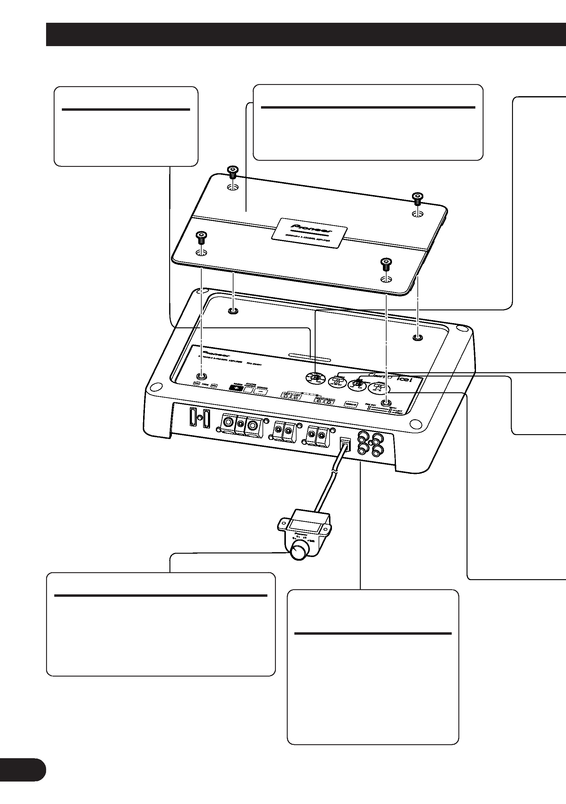
Setting the Unit
Power Indicator
The power indicator
lights when the power
is switched on.
Top Cover
Before setting up the unit, unfasten the
screws with a 4 mm hexagonal wrench
and remove the top cover.
Bass Boost Control
You can select a bass boost level from
0, 6, 9 and 12 dB.
For instruction of connecting the bass
boost remote control to the amplifier,
see the "Connection Diagram" section.
BFC (Beat Frequency
Control) Switch
BFC switch is on the bot-
tom of the unit. If you hear
a beat while listening to an
AM broadcast with your car
stereo, change the BFC
switch using a small stan-
dard tip screwdriver.
·To adjust the switch, use standard tip screwdriver if needed.
ENGLISH
ESPAÑOL
DEUTSCH
FRANÇAIS
ITALIANO
NEDERLANDS
êìëëäàâ
4
Gain Control
If the sound level is too low, even when the volume of the car stereo used along with this
power amplifier is turned up, turn gain control clockwise. If the sound distorts when the vol-
ume is turned up, turn the gain control counter-clockwise.
·When using with an RCA equipped car stereo (standard output of 500 mV), set to the NORMAL
position. When using with an RCA equipped Pioneer car stereo with max. output of 4 V or more,
adjust level to match the car stereo output level.
· If you hear too much noise when using the speaker input terminals, turn the gain control
counter-clockwise.
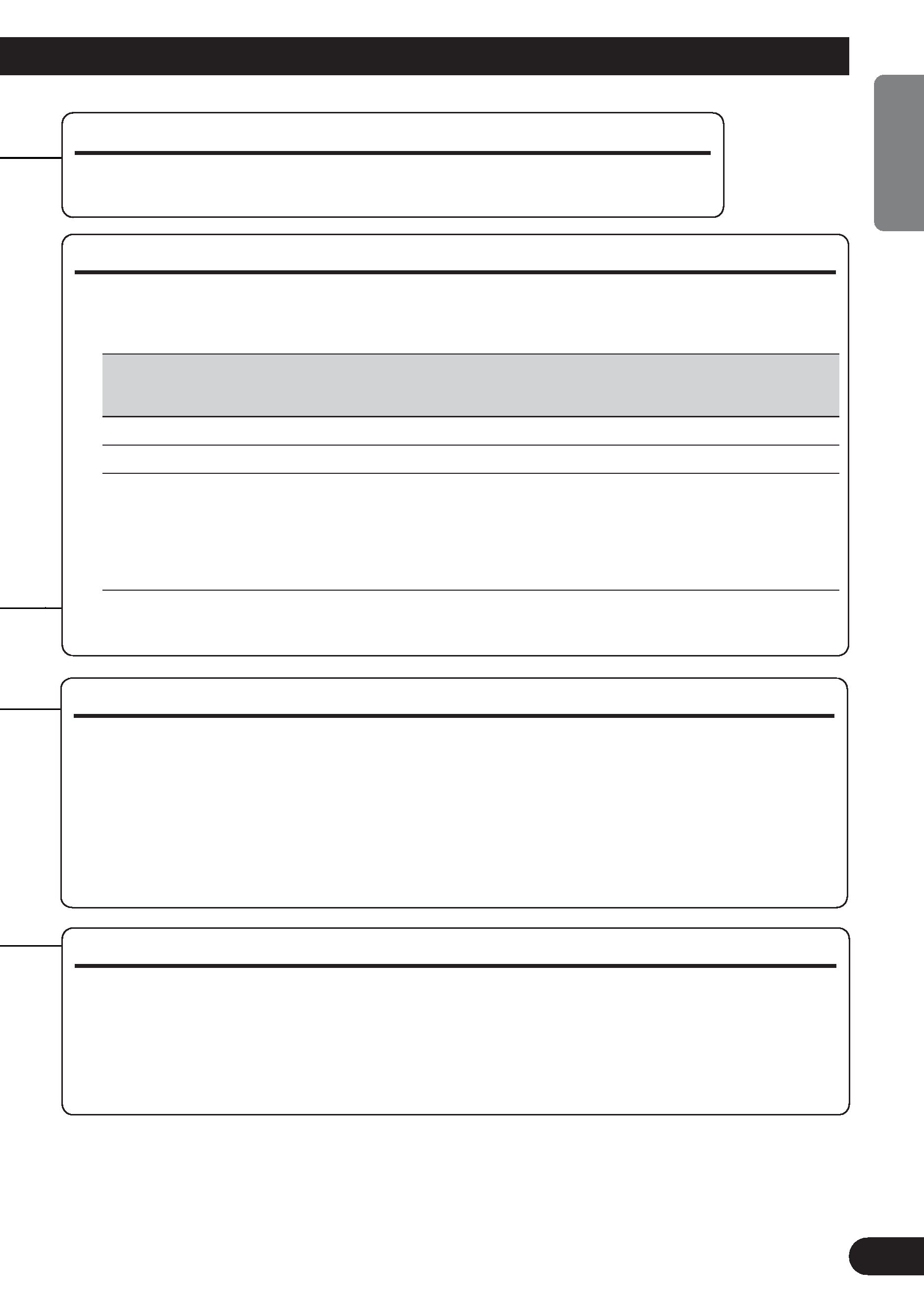
LPF (Low-Pass Filter)/HPF (High-Pass Filter) Select Switch
Set the LPF/HPF select switch as follows according to the type of speaker that is connected
to the speaker output connector and the car stereo system:
LPF/HPF Select
Audio frequency range
Speaker
Remarks
Switch
to be output
Type
LPF (Left)
* -- 40 Hz to 500 Hz
Subwoofer
Connect a subwoofer.
OFF (Center)
Full range
Full range
HPF (Right)
* 40 Hz to 500 Hz --
Full range
Use if you want to cut the
very low frequency range*
because it is not necessary
for the speakers you are
using.
* See the "Cut Off Frequency Control" section.
Cut Off Frequency Control
If the LPF/HPF select switch is set to LPF or HPF, you can select a cut off
frequency from 40 Hz to 500 Hz.
Input Switch
It is possible to input from a car stereo external output (subwoofer output) or a car stereo
speaker output. When using an external output (subwoofer output), slide the switch to the
left. For connection instructions, see the "Connection Diagram" section. When using a
speaker output, slide the switch to the right. In this case, it is necessary to use the supplied
speaker input wire with RCA pin cord. For details, see the "Using the Speaker Input" sec-
tion.