ORDER NO.
PIONEER CORPORATION 4-1, Meguro 1-chome, Meguro-ku, Tokyo 153-8654, Japan
PIONEER ELECTRONICS (USA) INC. P.O. Box 1760, Long Beach, CA 90801-1760, U.S.A.
PIONEER EUROPE NV Haven 1087, Keetberglaan 1, 9120 Melsele, Belgium
PIONEER ELECTRONICS ASIACENTRE PTE. LTD. 253 Alexandra Road, #04-01, Singapore 159936
PIONEER CORPORATION 2008
2008 Printed in Japan
OPEN/CLOSE
HOME
MENU
RETURN
ENTER
TOP MENU
MENU
USB
DVD/USB
STANDBY/ON
2
5
36
7
9
8
12
13
DV-310-S
RRV3756
DVD PLAYER
DV-310-S
DV-310-K
THIS MANUAL IS APPLICABLE TO THE FOLLOWING MODEL(S) AND TYPE(S).
Model
Type
Power Requirement
Region No.
Remarks
DV-310-S
WYXZT5
AC 220 V to 240V
2
DV-310-S
WSXZT5
AC 220 V to 240V
5
DV-310-K
WYXZT5
AC 220 V to 240V
2
DV-310-K
WSXZT5
AC 220 V to 240V
5
For details, refer to "Important Check Points for good servicing".
T-ZZV MAY
2
DV-310-S
1
2
3
4
A
B
C
D
E
F
1
2
3
4
SAFETY INFORMATION
This service manual is intended for qualified service technicians ; it is not meant for the casual
do-it-yourselfer. Qualified technicians have the necessary test equipment and tools, and have been
trainedto properly and safely repair complex products such as those covered by this manual.
Improperly performed repairs can adversely affect the safety and reliability of the product and may
void the warranty. If you are not qualified to perform the repair of this product properly and safely,
you should not risk trying to do so and refer the repair to a qualified service technician.
WARNING !
THE AEL (ACCESSIBLE EMISSION LEVEL) OF THE LASER POWER OUTPUT IS LESS THAN CLASS 1
BUT THE LASER COMPONENT IS CAPABLE OF EMITTING RADIATION EXCEEDING THE LIMIT FOR
CLASS 1.
A SPECIALLY INSTRUCTED PERSON SHOULD DO SERVICING OPERATION OF THE APPARATUS.
LASER DIODE CHARACTERISTICS
FOR DVD : MAXIMUM OUTPUT POWER : 5 mW
WAVELENGTH : 650 nm
FOR CD :
MAXIMUM OUTPUT POWER : 5 mW
WAVELENGTH : 780 nm
Additional Laser Caution
: See page 26.
1.
· Laser diode is driving with Q2303,Q2305(650nm LD) and Q2302,
Q2304(780nm LD)on the DVD MT PCB Assy.
Therefore, when short-circuit between the emitter and collector of these
transistors or the base voltage is supplied for transistors turn on, the
laser oscillates. (failure mode)
· In the test mode
, there is the mode that the laser oscillates except
for the disc judgment and playback. LD ON mode in the test mode
oscillates with the laser forcibly.
2. When the cover is open, close viewing through the objective lens with
the naked eye will cause exposure to the laser beam.
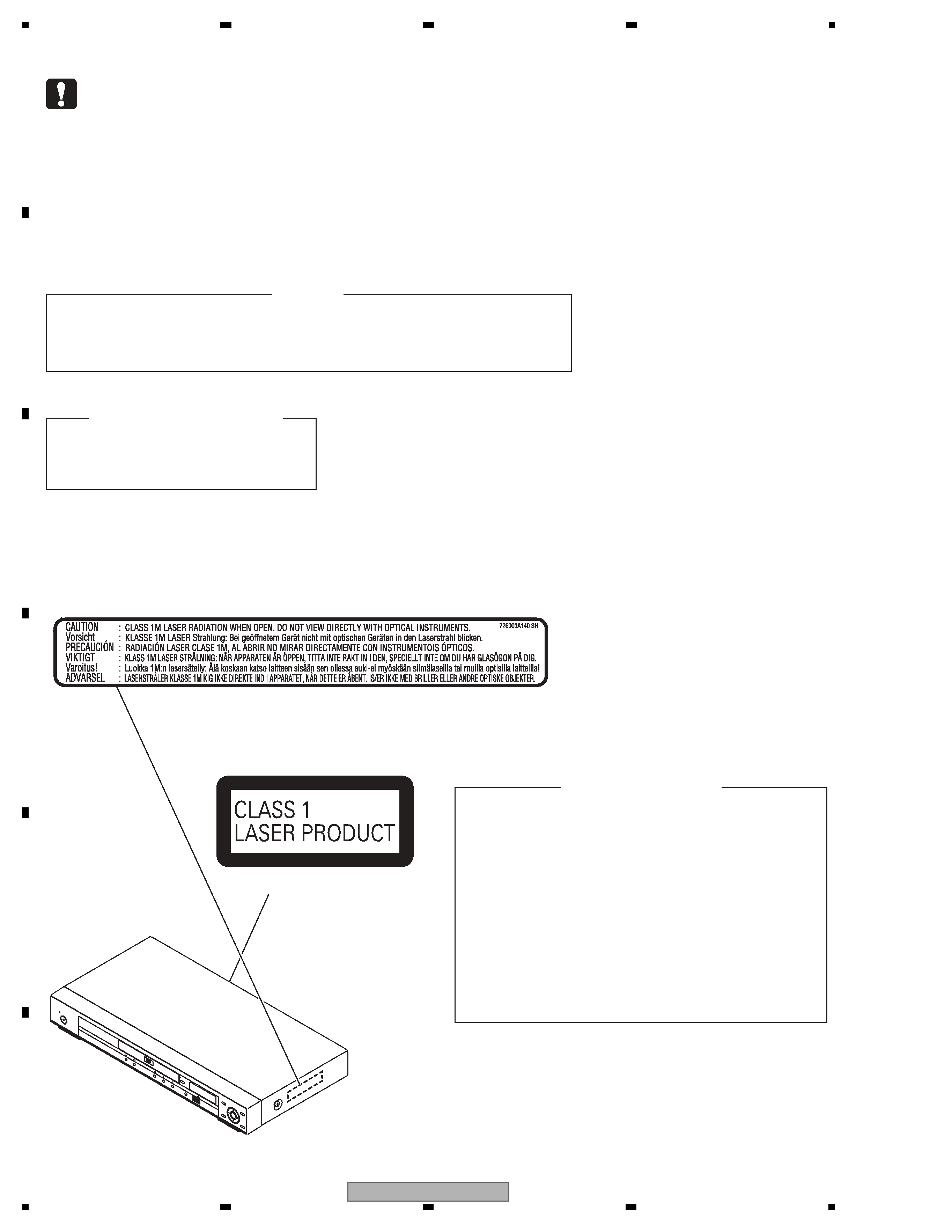
LABEL CHECK
(Printed on the Rear Panel)
Location: inside of the unit
OPE
N/C
LOS
E
HOM
E
MEN
U
RET
URN
ENT
ER
TOP
MEN
U
MEN
U
USB
DVD
/US
B
STA
NDB
Y/O
N
3
DV-310-S
5
6
7
8
5
6
7
8
A
B
C
D
E
F

4
DV-310-S
1
2
3
4
A
B
C
D
E
F
1
2
3
4
CONTENTS
SAFETY INFORMATION ..........................................................................................................................................................2
1. SERVICE PRECAUTIONS ....................................................................................................................................................5
1.1 NOTES ON SOLDERING ...............................................................................................................................................5
1.2 WHEN REPLACING DVD DECK ....................................................................................................................................5
1.3 DISC REMOVAL METHOD.............................................................................................................................................6
2. SPECIFICATIONS .................................................................................................................................................................7
2.1 ACCESSORIES ..............................................................................................................................................................7
2.2 SPECIFICATIONS...........................................................................................................................................................8
2.3 DISC/CONTENT FORMAT .............................................................................................................................................9
2.4 PANEL FACILITILES .....................................................................................................................................................11
3. BASIC ITEMS FOR SERVICE.............................................................................................................................................13
3.1 CHECK POINTS AFTER SERVICING..........................................................................................................................13
3.2 PCB LOCATIONS .........................................................................................................................................................14
3.3 JIGS LIST .....................................................................................................................................................................15
4. BLOCK DIAGRAM...............................................................................................................................................................16
4.1 OVERALL WIRING DIAGRAM......................................................................................................................................16
4.2 OVERALL BLOCK DIAGRAM.......................................................................................................................................18
4.3 DVD LOADER/MPEG BLOCK DIAGRAM.....................................................................................................................19
4.4 POWER BLOCK DIAGRAM..........................................................................................................................................20
5. DIAGNOSIS.........................................................................................................................................................................21
5.1 TROUBLE SHOOTING .................................................................................................................................................21
5.2 METHOD FOR DIAGNOSING DEGRADATION OF THE LDS ON THE PICKUP ASSY .............................................25
6. SERVICE MODE .................................................................................................................................................................26
6.1 SERVICE MODE PROCEDURE...................................................................................................................................26
6.2 SERVICE MODE IN ......................................................................................................................................................27
6.3 DISPLAY SPECIFICATION OF THE SERVICE MODE ................................................................................................28
6.4 FUNCTIONAL SPECIFICATION OF THE SHORTCUT KEY........................................................................................29
6.5 FUNCTIONAL SPECIFICATION OF THE SERVICE MODE ........................................................................................30
7. DISASSEMBLY....................................................................................................................................................................31
8. EACH SETTING AND ADJUSTMENT ................................................................................................................................36
8.1 RE-WRITE FOR DVD FIRMWAVE ...............................................................................................................................36
9. EXPLODED VIEWS AND PARTS LIST...............................................................................................................................38
9.1 PACKING ......................................................................................................................................................................38
9.2 EXTERIOR SECTION...................................................................................................................................................40
9.3 06 DVD MECHA SECTION...........................................................................................................................................42
10. SCHEMATIC DIAGRAM ....................................................................................................................................................44
10.1 DVD MT PCB ASSY(1/6) ............................................................................................................................................44
10.2 DVD MT PCB ASSY(2/6) ............................................................................................................................................46
10.3 DVD MT PCB ASSY(3/6) ............................................................................................................................................48
10.4 DVD MT PCB ASSY(4/6) ............................................................................................................................................50
10.5 DVD MT PCB ASSY(5/6) ............................................................................................................................................52
10.6 DVD MT PCB ASSY(6/6) ............................................................................................................................................54
10.7 OPERATION PCB ASSY ............................................................................................................................................56
10.8 POWER PCB ASSY(1/2) ............................................................................................................................................58
10.9 POWER PCB ASSY(2/2) ............................................................................................................................................60
10.10 WAVEFORMS ...........................................................................................................................................................62
11. PCB CONNECTION DIAGRAM ........................................................................................................................................64
11.1 DVD MT PCB ASSY....................................................................................................................................................65
11.2 OPERATION PCB ASSY ............................................................................................................................................67
11.3 POWER PCB ASSY....................................................................................................................................................68
11.4 LOADING MOTOR and SW ........................................................................................................................................70
12. PCB PARTS LIST ..............................................................................................................................................................71
5
DV-310-S
5
6
7
8
5
6
7
8
A
B
C
D
E
F
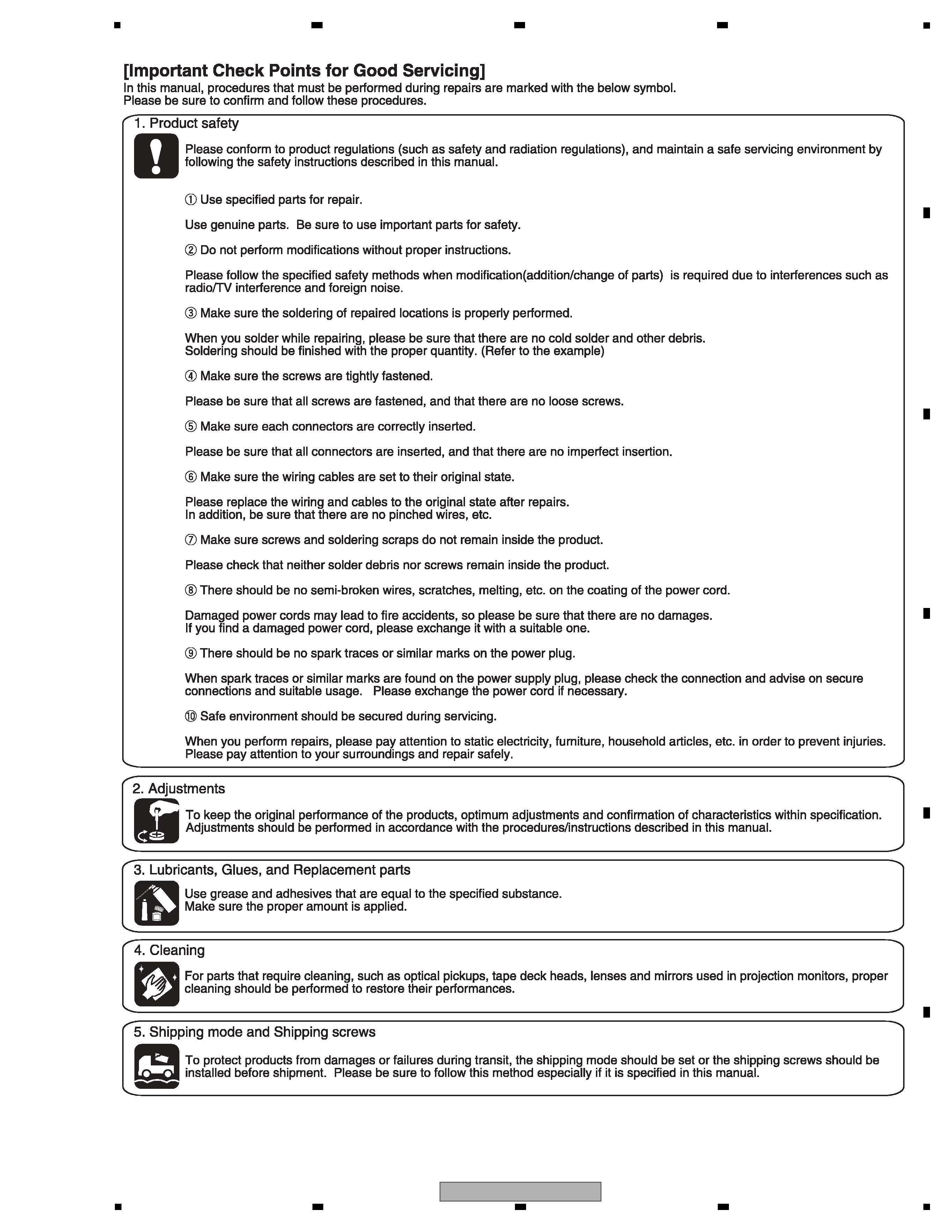
1. SERVICE PRECAUTIONS
1.1 NOTES ON SOLDERING
1.2 WHEN REPLACING DVD DECK
· For environmental protection, lead-free solder is used on the printed circuit boards mounted in this unit.
Be sure to use lead-free solder and a soldering iron that can meet specifications for use with lead-free solders for repairs
accompanied by reworking of soldering.
· Compared with conventional eutectic solders, lead-free solders have higher melting points, by approximately 40
°C.
Therefore, for lead-free soldering, the tip temperature of a soldering iron must be set to around 373
°C in general, although
the temperature depends on the heat capacity of the PC board on which reworking is required and the weight of the tip of
the soldering iron.
Do NOT use a soldering iron whose tip temperature cannot be controlled.
Compared with eutectic solders, lead-free solders have higher bond strengths but slower wetting times and higher melting
temperatures (hard to melt/easy to harden).
The following lead-free solders are available as service parts:
· Parts numbers of lead-free solder:
GYP1006 1.0 in dia.
GYP1007 0.6 in dia.
GYP1008 0.3 in dia.
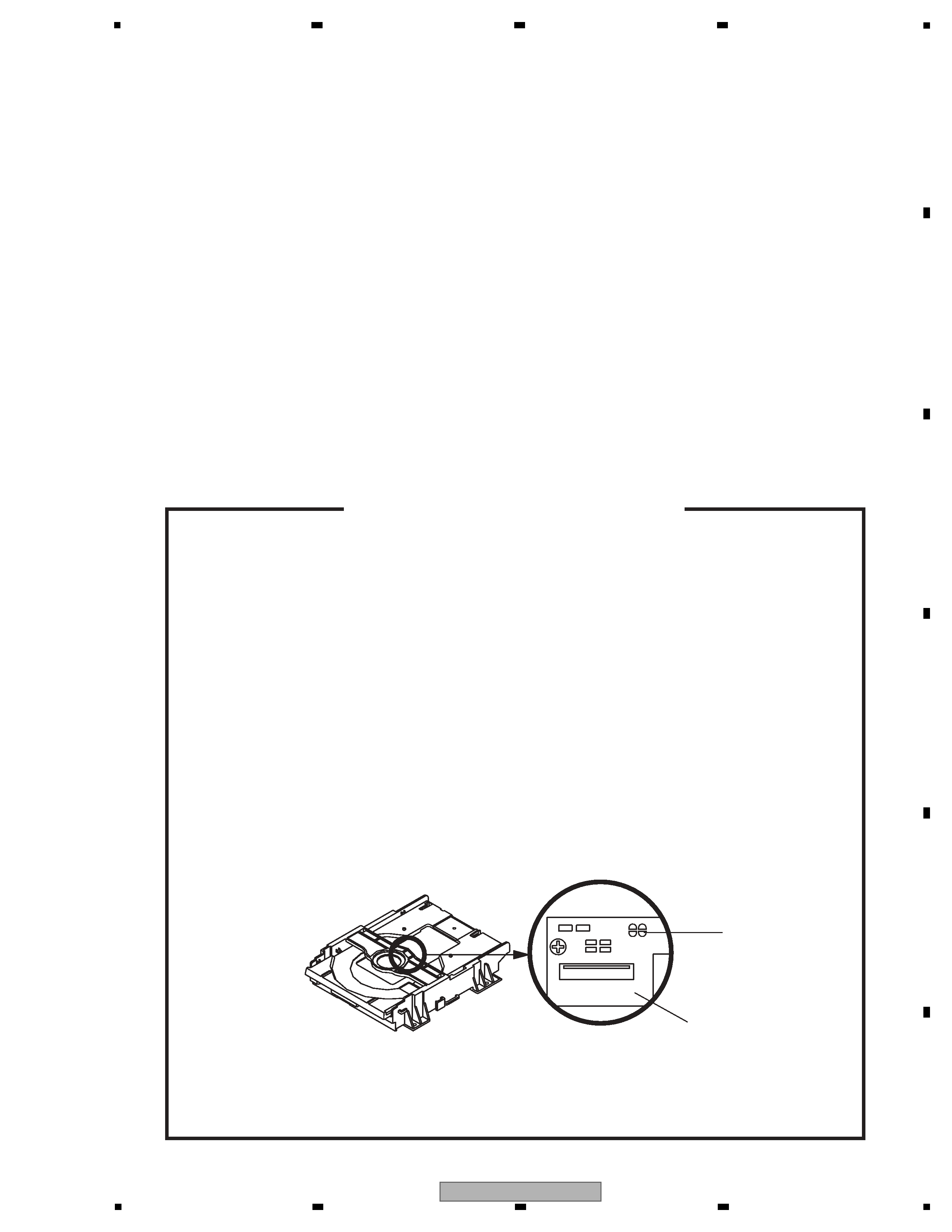
Before removing Pick Up PCB and DVD PCB connector, short circuit the position shown in Fig. 1 using
a soldering iron. If you remove the DVD Deck with no soldering, the Laser may be damaged.
WHEN REPLACING DVD DECK
[ Removing the DVD Deck ]
[ Installing the DVD Deck ]
Remove all the soldering on the short circuit position after the connection of Pick Up PCB and DVD
PCB connector.
NOTE
Fig. 1
Before your operation, please read "PREPARATION OF SERVICING" .
Use the Lead Free solder.
Manual soldering conditions
· Soldering temperature: 320
± 20°C
· Soldering time: Within 3 seconds
· Soldering combination: Sn-3.0Ag-0.5Cu
When Soldering/Removing of solder, use the draw in equipment over the Pick Up Unit to prevent the
Flux smoke from it.
·
·
·
·
Short circuit using a
soldering iron.
Pick Up PCB