© 2000-10
B51-8549-00 (N) 607
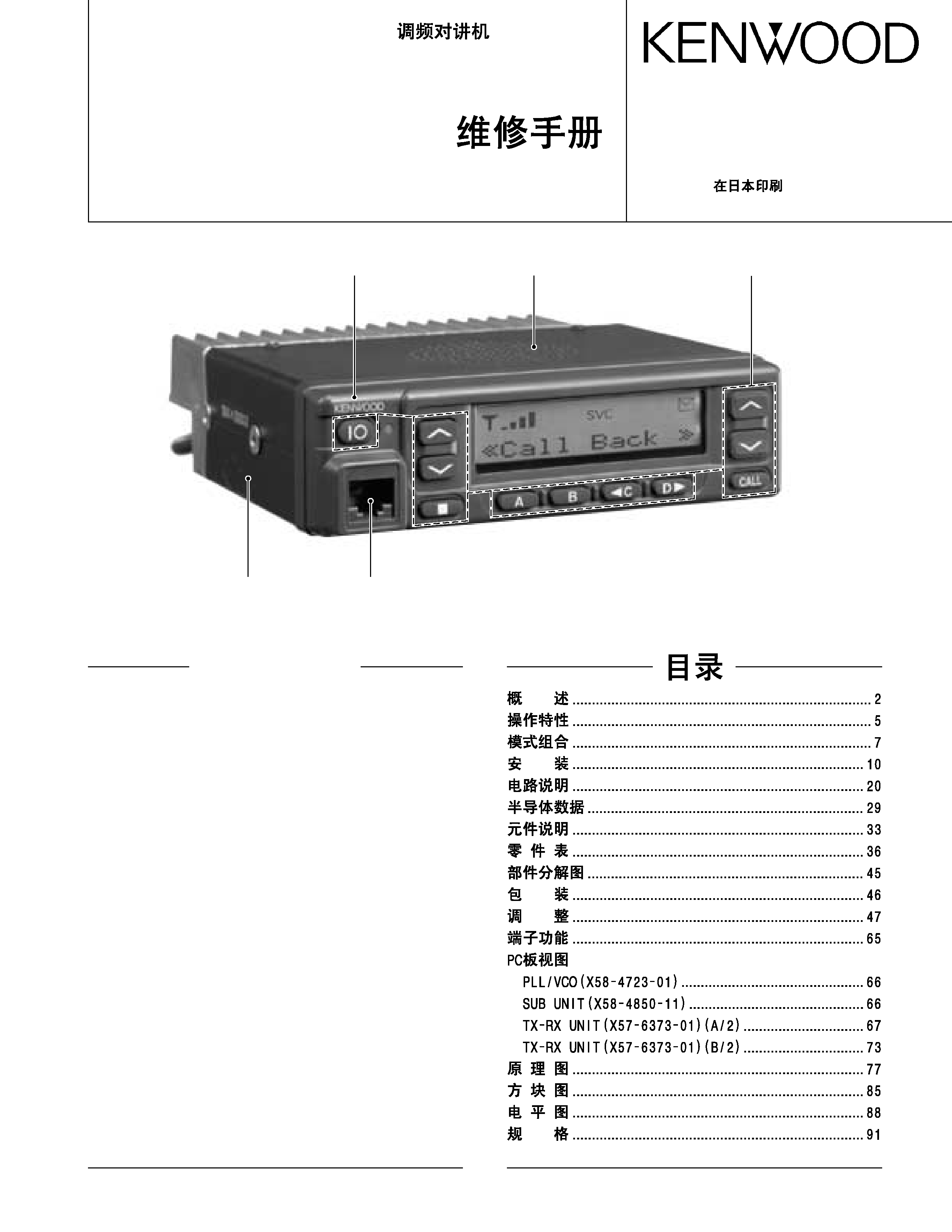
TK-885
SERVICE MANUAL /
GENERAL ................................................................. 2
OPERATING FEATURES ......................................... 5
REALIGNMENT ........................................................ 7
INSTALLATION ...................................................... 10
CIRCUIT DESCRIPTION ......................................... 20
SEMICONDUCTOR DATA ..................................... 29
DESCRIPTION OF COMPONENTS ....................... 33
PARTS LIST ............................................................ 36
EXPLODED VIEW .................................................. 45
PACKING ................................................................ 46
ADJUSTMENT ....................................................... 47
TERMINAL FUNCTION ......................................... 64
PC BOARD VIEWS
PLL/VCO (X58-4723-01) ................................... 66
SUB UNIT (X58-4850-11) .................................. 66
TX-RX UNIT (X57-6373-01) (A/2)..................... 67
TX-RX UNIT (X57-6373-01) (B/2) ..................... 73
SCHEMATIC DIAGRAM ........................................ 77
BLOCK DIAGRAM .................................................. 85
LEVEL DIAGRAM ................................................... 88
SPECIFICATIONS ................................................... 90
CONTENTS
Cabinet (Upper)
(A01-2165-13)
Cabinet (Lower)
(A01-2166-13)
Modular jack
(E08-0877-05)
Panel assy
(A62-0642-03)
Key top
(K29-5422-02)
UHF FM TRANSCEIVER / UHF
2
TK-885
GENERAL /
INTRODUCTION
SCOPE OF THIS MANUAL
This manual is intended for use by experienced techni-
cians familiar with similar types of commercial grade com-
munications equipment. It contains all required service infor-
mation for the equipment and is current as of the publication
date. Changes which may occur after publication are cov-
ered by either Service Bulletins or Manual Revisions. These
are issued as required.
ORDERING REPLACEMENT PARTS
When ordering replacement parts or equipment informa-
tion, the full part identification number should be included.
This applies to all parts : components, kits, or chassis. If the
part number is not known, include the chassis or kit number
of which it is a part, and a sufficient description of the re-
quired component for proper identification.
PERSONNEL SAFETY
The following precautions are recommended for person-
nel safety :
DO NOT transmit if someone is within two feet (0.6 meter)
of the antenna.
DO NOT transmit until all RF connectors are verified se-
cure and any open connectors are properly terminated.
SHUT OFF and DO NOT operate this equipment near elec-
trical blasting caps or in an explosive atmosphere.
All equipment should be properly grounded before power-
up for safe operation.
This equipment should be serviced by a qualified techni-
cian only.
PRE-INSTALLATION CONSIDERNATIONS
1. UNPACKING
Unpack the radio from its shipping container and check
for accessory items. If any item is missing, please contact
KENWOOD immediately.
2. PRE-INSTALLATION CHECKOUT
2-1. Introduction
Each radio is adjusted and tested before shipment. How-
ever, it is recommended that receiver and transmitter opera-
tion be checked for proper operation before installation.
2-2. Testing
The radio should be tested complete with all cabling and
accessories as they will be connected in the final installation.
Transmitter frequency, deviation, and power output should
be checked, as should receiver sensitivity, squelch operation,
and audio output. QT equipment operation should be veri-
fied.
3
TK-885
GENERAL /
3. PLANNING THE INSTALLATION
3-1. General
Inspect the vehicle and determine how and where the ra-
dio antenna and accessories will be mounted.
Plan cable runs for protection against pinching or crush-
ing wiring, and radio installation to prevent overheating.
3-2. Antenna
The favored location for an antenna is in the center of a
large, flat conductive area, usually at the roof center. The
trunk lid is preferred, bond the trunk lid and vehicle chassis
using ground straps to ensure the lid is at chassis ground.
3-3. Radio
The universal mount bracket allows the radio to be
mounted in a variety of ways. Be sure the mounting surface
is adequate to support the radio's weight. Allow sufficient
space around the radio for air cooling. Position the radio close
enough to the vehicle operator to permit easy access to the
controls when driving.
3-4. DC Power and wiring
1. This radio may be installed in negative ground electrical
systems only. Reverse polarity will cause the cable fuse
to blow. Check the vehicle ground polarity before installa-
tion to prevent wasted time and effort.
2. Connect the positive power lead directly to the vehicle
battery positive terminal. Connecting the Positive lead to
any other positive voltage source in the vehicle is not rec-
ommended.
3. Connect the ground lead directly to the battery negative
terminal.
4. The cable provided with the radio is sufficient to handle
the maximum radio current demand. If the cable must be
extended, be sure the additional wire is sufficient for the
current to be carried and length of the added lead.
4. INSTALLATION PLANNING - CONTROL STATIONS
4-1. Antenna system
Control station. The antenna system selection depends
on many factors and is beyond the scope of this manual.
Your KENWOOD dealer can help you select an antenna sys-
tem that will best serve your particular needs.
4-2. Radio location
Select a convenient location for your control station radio
which is as close as practical to the antenna cable entry point.
Secondly, use your system's power supply (which supplies
the voltage and current required for your system). Make sure
sufficient air can flow around the radio and power supply to
allow adequate cooling.
4
TK-885
GENERAL /
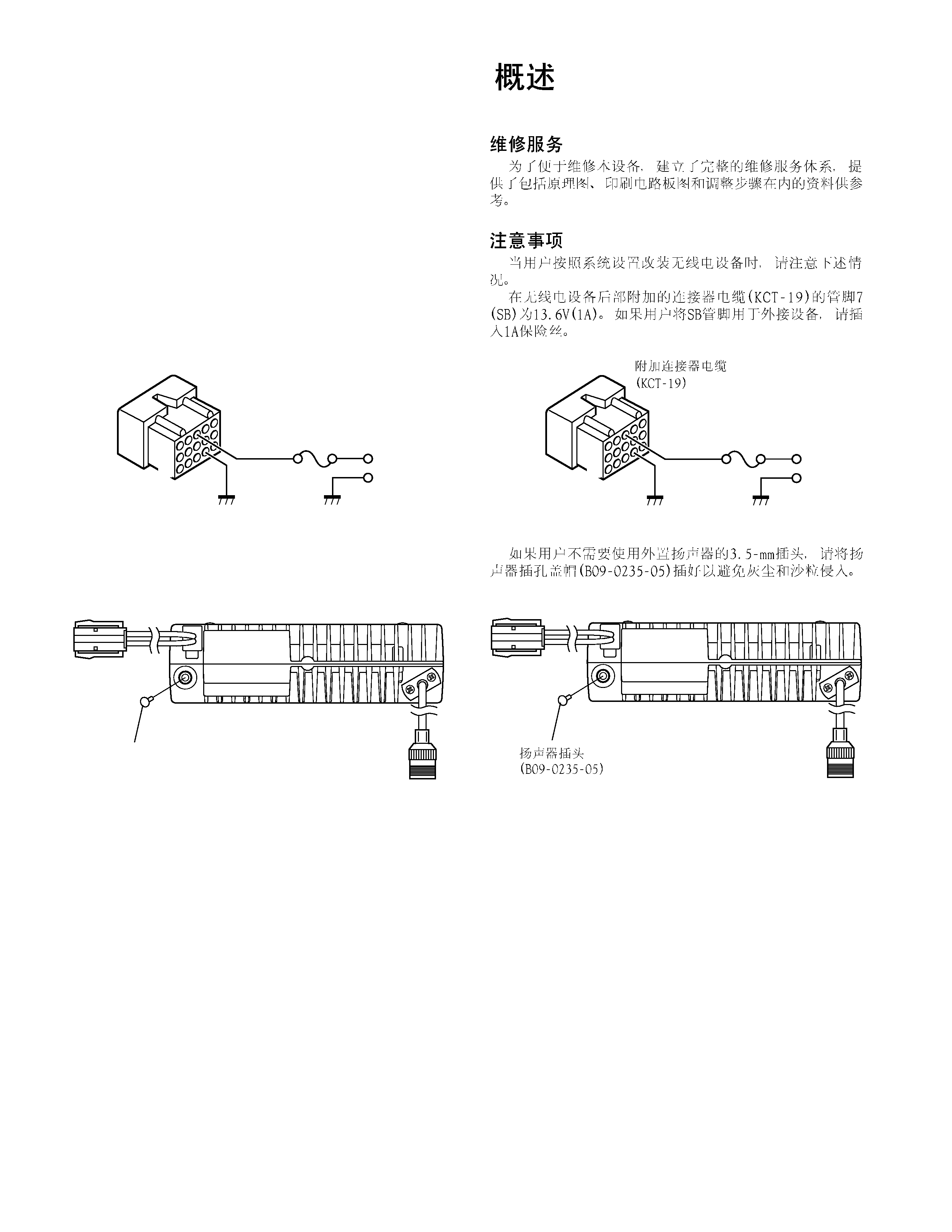
SERVICE
This radio is designed for easy servicing. Refer to the
schematic diagrams, printed circuit board views, and align-
ment procedures contained in this manual.
Note
When you modify your radio as described in system set-
up, take the following precaution.
The rating of pin 7 (SB) of the accessory connector cable
(KCT-19) on the rear of the radio is 13.6V (0.75A). Insert a 1A
fuse if you use the SB pin for external equipment.
Accessory connector
cable (KCT-19)
If you do not intend to use the 3.5-mm jack for the exter-
nal speaker, fit the supplied speaker-jack cap (B09-0235-05)
to stop dust and sand getting in.
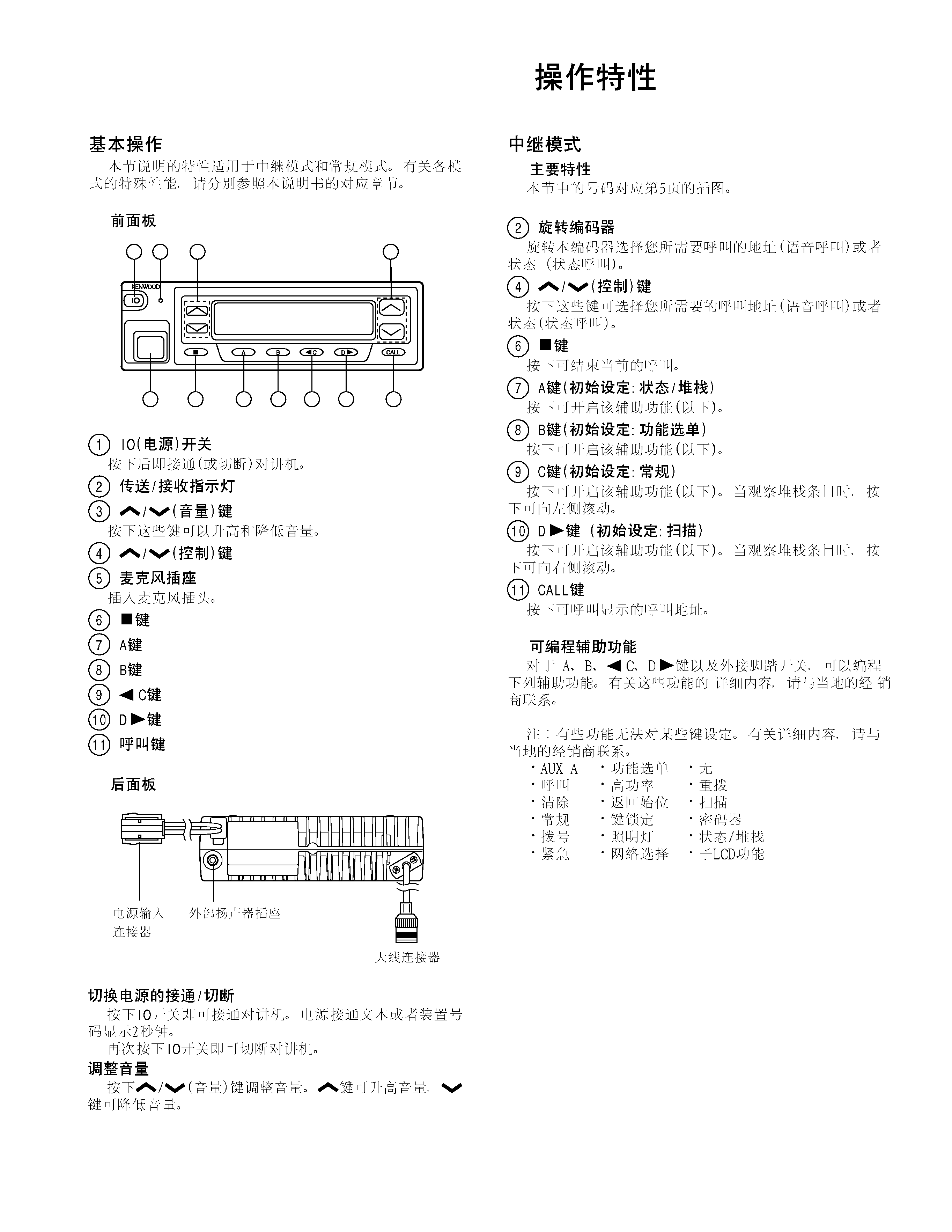
1
3
+
7
6
13
15
Speaker-jack cap
(B09-0235-05)
1
3
+
7
6
13
15
5
TK-885
OPERATING FEATURES /
#
$
%
&
'
!"