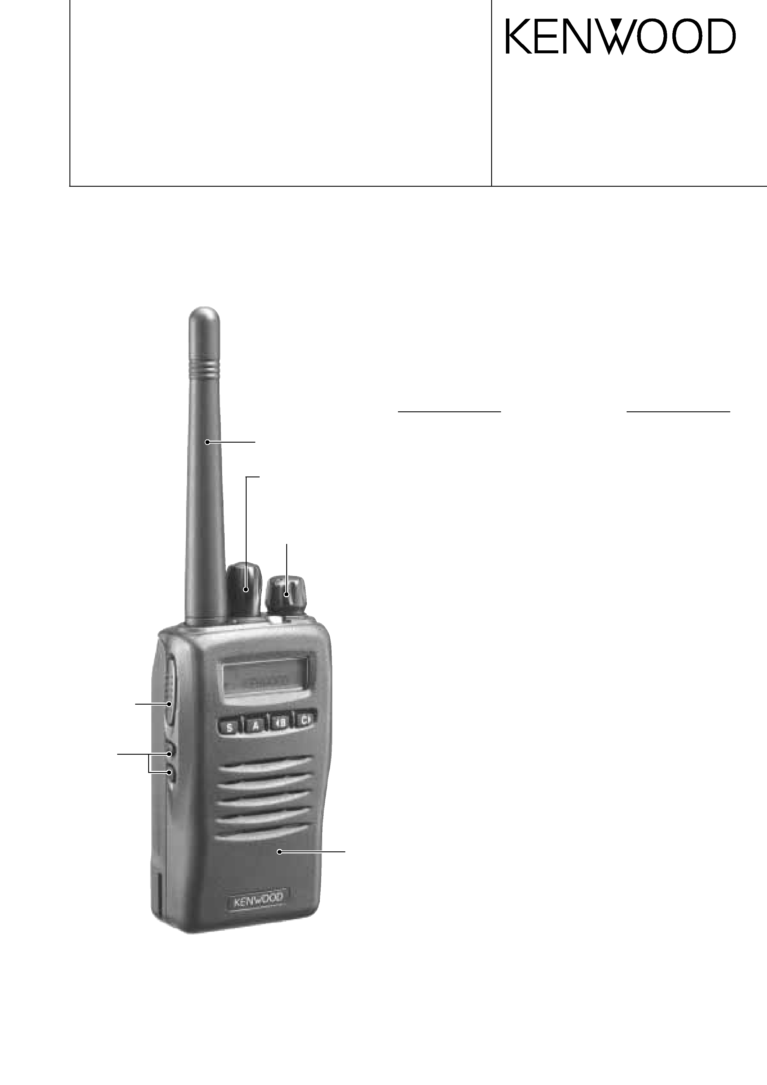
UHF FM TRANSCEIVER /
UHF FM
TK-3148
© 2003-9 PRINTED IN JAPAN
B51-8656-00 (S) PDF
SERVICE MANUAL /
GENERAL ....................................................................... 2
SYSTEM SET-UP ........................................................... 3
OPERATING FEATURES ............................................... 4
REALIGNMENT .............................................................. 6
CIRCUIT DESCRIPTION ............................................... 10
SEMICONDUCTOR DATA ........................................... 19
COMPONENTS DESCRIPTION ................................... 21
PARTS LIST .................................................................. 23
EXPLODED VIEW ......................................................... 31
PACKING ...................................................................... 32
ADJUSTMENT ............................................................. 33
TERMINAL FUNCTION ................................................ 52
PC BOARD VIEWS
TX-RX UNIT (X57-6413-01) (A/3) .......................... 54
TX-RX UNIT (X57-6413-01) (B/3),(C/3) ................. 58
SCHEMATIC DIAGRAM ............................................... 60
LEVEL DIAGRAM ......................................................... 65
BLOCK DIAGRAM ........................................................ 66
KSC-25 / KNB-24L ....................................................... 68
SPECIFICATIONS ......................................................... 69
CONTENTS
Knob (ENC)
(K29-9134-03)
Knob (VOL)
(K29-9133-03)
Cabinet assy
(A02-3653-14)
Knob (PTT)
(K29-9131-03)
Helical Antenna
(T90-1032-25)
Key top
(SW1,SW2)
(K29-9132-03)

TK-3148
2
INTRODUCTION
SCOPE OF THIS MANUAL
This manual is intended for use by experienced technicians
familiar with similar types of commercial grade
communications equipment. It contains all required service
information for the equipment and is current as of the
publication date. Changes which may occur after publication
are covered by either Service Bulletins or Manual Revisions.
These are issued as required.
ORDERING REPLACEMENT PARTS
When ordering replacement parts or equipment information,
the full part identification number should be included. This
applies to all parts : components, kits, or chassis. If the part
number is not known, include the chassis or kit number of
which it is a part, and a sufficient description of the required
component for proper identification.
PERSONNEL SAFETY
The following precautions are recommended for personnel
safety:
DO NOT transmit until all RF connectors are verified secure
and any open connectors are properly terminated.
SHUT OFF and DO NOT operate this equipment near
electrical blasting caps or in an explosive atmosphere.
This equipment should be serviced by a qualified technician only.
SERVICE
This radio is designed for easy servicing. Refer to the
schematic diagrams, printed circuit board views, and alignment
procedures contained within.
............................................................................................... 2
...................................................................................... 3
...................................................................................... 4
...................................................................................... 6
.................................................................................... 10
................................................................................ 19
.................................................................................... 21
........................................................................................ 23
................................................................................ 31
............................................................................................. 32
............................................................................................. 33
.................................................................................... 52
PC
TXRX (X57-6413-01) (A/3) ................................... 54
TXRX (X57-6413-01) (B/3),(C/3) ......................... 58
........................................................................................ 60
........................................................................................ 65
........................................................................................ 66
KSC-25 / KNB-24L .................................................................... 68
.........................................................................................
GENERAL /
TK-3148
3
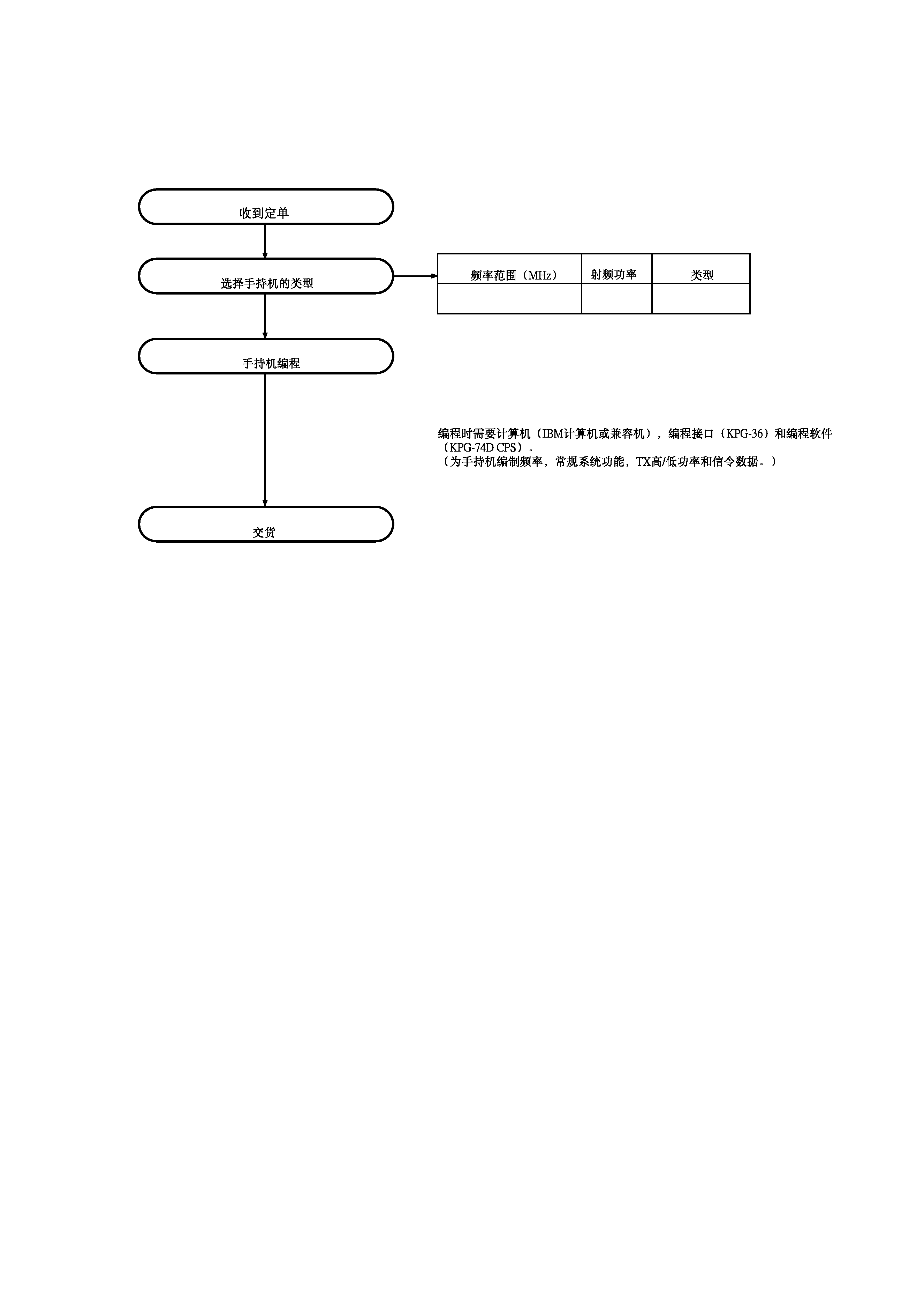
SYSTEM SET-UP /
Merchandise received
Choose the type of transceiver
Transceiver programming
Delivery
TX/RX
4.0W
TK-3148 C
Frequency range (MHz)
RF power
Type
A personal computer (IBM PC or compatible), programming
interface (KPG-36), and programming software (KPG-74D CPS)
are required for programming.
(The frequency, conventional system features, TX power HI/LOW,
and signalling data are programmed for the transceiver.)
350~390
SYSTEM SET-UP /
TK-3148
4
6
7
11
12
13
14
4
5
15
9
10
3
2
1
8
OPERATING FEATURES /
1. Operation Features
The TK-3148 is a UHF FM Radio designed in both Trunking
Mode and Conventional Mode.
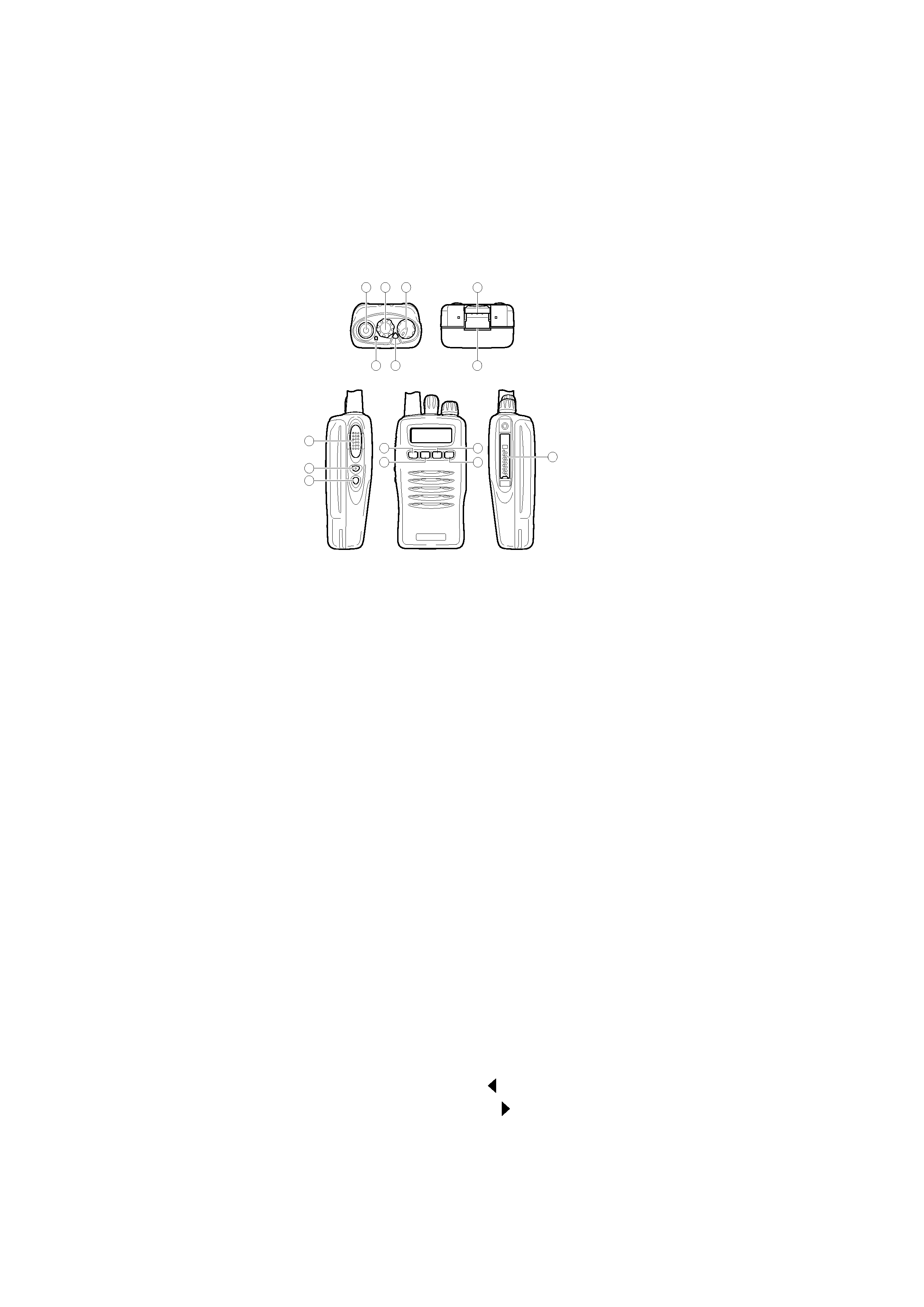
2. Transceiver Controls and Indicators
2-1. Physical Layout
2-2. Panel controls
The key on the top and front panel is momentary-type push
buttons. The functions of these keys and knob are explained
below.
1 Antenna connector
Connect the antenna here.
2 Rotary encoder
3 POWER switch/ VOLUME control
Turn clockwise to switch ON the transceiver. Rotate to
adjust the volume. Turn counterclockwise fully to switch
OFF the transceiver.
4 Transmit/ Receive indicator
5 Auxiliary (orange) key
6 Battery pack safety catch
Flip this catch to prevent accidentally pressing the battery
pack release latch.
7 Battery pack release latch
Pull back on this latch to release the battery pack.
8 PTT (Push-To-Talk) switch
9 Side 1 key
0 Side 2 key
- S key
= A key
~
2 B key
! C
3 key
@ Universal connector
Connect the speaker/ microphone here. Otherwise, keep
the supplied cover in place.
2-2.
1
2
3
/
4 /
5
()
6
7
8
PTT ()
9
1
0 2
-
S
=
A
~
B
!
C
@
/
1.
TK-3148 UHF
2.
2-1.

TK-3148
5
2-3. Key functions
Trunking mode
2 Rotary encoder
Rotate this encoder to select your desired call address
(voice calls/dialing) or status (status calls).
4 Transmit indicator
Lights red while transmitting.
5 Auxiliary (orange) key (default setting: None)
Press to activate its auxiliary function.
8 PTT (Push-To-Talk) switch
Press to transmit. Also press to initiate a call if "PTT to
Initiate Call" has been programmed.
9 Side 1 key (default setting: Clear)
Press to activate its auxiliary function.
0 Side 2 key (default setting: Call)
Press to activate its auxiliary function.
- S key (default setting: Status/ Stack)
Press to activate its auxiliary function.
= A key (default setting: Function Menu)
Press to activate its auxiliary function.
~
2 B key (default setting: Conventional)
Press to activate its auxiliary function. Also press to scroll
left while viewing stack entries.
! C
3 key (default setting: Scan)
Press to activate its auxiliary function. Also press to scroll
right while viewing stack entries.
Conventional mode
2 Rotary encoder
Rotate this encoder to select your desired channel.
4 Transmit/ Receive indicator
Lights green while receiving a signal. Lights red while
transmitting.
8 PTT (Push-To-Talk) switch
Press this switch, then speak into the microphone to call a
station.
9 Side 1 key
Press to return to Trunking mode.
0 Side 2 key
Press to turn the monitor function ON in order to monitor
your selected channel.
- S key
Press to turn the display and keypad backlight ON.
The backlight remains ON for 5 seconds.
= A key
Press to add/delete channel(s) to/from Scan list.
! C
3 key
Press to turn Scan ON (or OFF).
OPERATING FEATURES /
2-3.
2
(/)
()
4
5
() (: )
8
PTT ()
" PTT "
9
1 (: )
0
2 (: )
-
S (: /)
=
A (: )
~
B (: )
!
C
(: )
2
4
8 PTT ()
9 1
0 2
- S
5
= A
!
C
()