© 2004-3 PRINTED IN JAPAN
B53-0147-00 (N) 1838
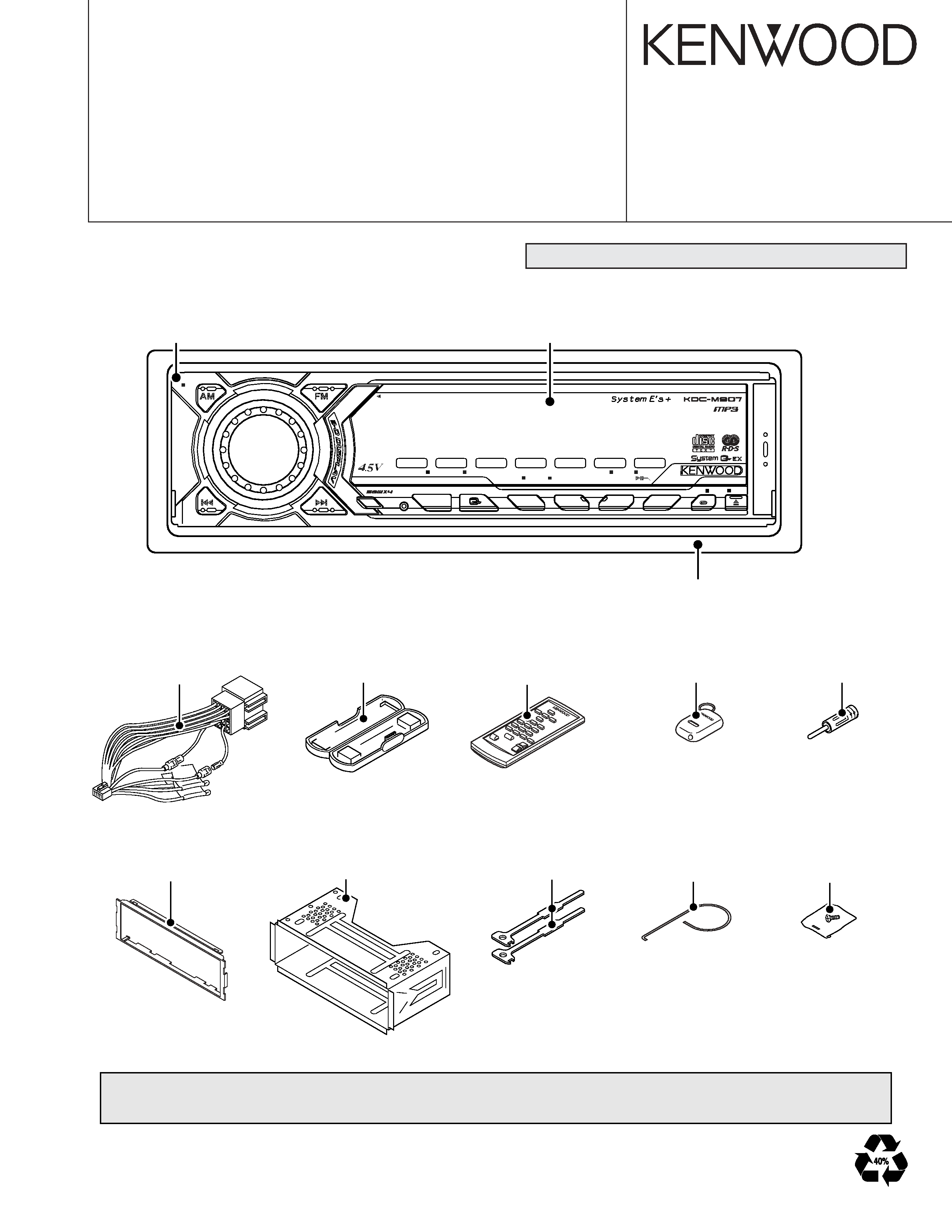
CD RECEIVER
KDC-M907
SERVICE MANUAL
PREOUT
PTY/D.REP
TI
RDS
LOUD
ST
ATT
P/S
IN
F.SEL
RDM
P.M/M.RDM
TI
SCN
NF
SRC
DAB
1/5
2/6
3/7
4/8
REP
MENU
AUD
OFF
ANG
SCRL
GSM
Panel assy
(A64-3381-02)
Front glass
(B10-4575-01)
DC cord
(E30-4942-05)
Remote con.assy
(A70-2026-05) RC-420
Antenna adaptor
(T90-0523-05)
Escutcheon
(B07-3009-02)
Mounting hardware assy
(J21-9716-03)
Lever
(D10-4562-04) x2
Torsion coil spring
(G01-2924-04)
Screw set
(N99-1704-05)
Remote con.assy
(A70-0886-15)
Plastic cabinet assy
(A02-1497-13)
Technical information is not in this service manual (block diagram, component description and microcomputer's terminal description).
Please refer to service manual for KDC-M9021 (B51-7901-00).
Escutcheon assy
(B07-3007-03)
CD mechanism extension cord (24PIN) : W05-0934-00
KDC-M907
2
TEST MODE
Test Mode
1. How to enter test mode
While holding the [1/5] key and the [3/7] key, reset the unit.
2. How to exit from test mode
While holding down the [4/8] key, reset the unit.
Note : Does not exit from test mode ACC OFF, Power OFF
or momentary power down.
3. Test mode reset status
· Sources are all OFF
· All display segment lit up
·Volume at -10dB (shows 30 on display)
· LOUD is OFF.
· CRSC is OFF regardless of whether switching function is
provided.
· SYSTEM Q is in FLAT
· BEEP sounds at momentarily pressing at any time.
4. Special displays in Tuner
When the following displays appear in tuner mode it shows
a problem with the front end.
·"TNE2P NG" : F/E is not aligned and EEPROM is in reset
(no settings) such as when shipped.
· "TNCON NG" : Cannot communicate with F/E (front-end).
5. K3I switching
Each time the Preset [6] key is pressed in Tuner mode,
switches one at a time through the following sequence :
AU TO
Forced WideForced MiddleForced
Narrow
AUTO.
When reset, displays the following in AUTO.
·AUTO
: FMA
·Forced Wide
: FMW
·Forced Middle : FMM
·Forced Narrow : FMN
6. CD receiver test mode specifications
· No automatic ejection during reset-start. Does not make
a CD check in reset with a CD loaded.
· Using the Track up key jumps to the following tracks.
No. 9
No. 15No. 10No. 11No. 12No. 13No. 14
and back to No. 9
· Using the Track down key moves 1 track down wards from
the track being played.
· When the total number of MP3 or WMA disc tracks is 9 or
less, playback starts from the first track.
· With the model equipped with the MP3 or MP3/WMP
mechanism, the mechanism model name and version
number are displayed at the bottom line.
7. Audio items
· Momentarily pressing the [Q] key calls up audio adjust-
ment mode.
· Pressing the [] key on the remote control calls up audio
alignment mode.
· An initial item is set to Feder.
· Continuous forward is disabled on the remote control.
· Bass/Middle/Treble/NF are settable in 3 steps of MIN/Cen-
ter/MAX with the [Track up/down] keys.
· Balance is settable in 3 steps of Left MAX/Center/Right
MAX with the [Track up/down] keys.
·Fader is settable in 3 steps of Rear MAX/Center/Front MAX
with the [Track up/down] keys.
· HPF is settable in 2 steps of THRU/220Hz with the [Track
up/down] keys.
· LPF is settable in 2 steps of THRU/120Hz with the [Track
up/down] keys.
· Bass f/Bass Q/Bass EXT/Middle f/Middle Q/Treble f do
not appear in the audio alignment.
8. Menu items
· The [DNPP/SBF] keys on the remote control calls up Menu
mode.
· Continuous forward is disabled on the remote control.
9. Backup current measurement
The MUTE terminal turns off 2 seconds (not 15 seconds)
after being reset in ACC off (backup on). (The panel and
CD mechanisms are disabled during this time.)
10. Special displays during All-Off with all lamps on
The following displays appear when the [preset] keys are
pressed with all display segment lit up.
[1/5]
· Version display (8 digits; Mo. Dy. Hr. Mn.)
key
(Display) SYS XXXXXXXX system microprocessor
PAN XXXXXXXX panel microprocessor
· Serial No. display (8 digits)
(Display) Sno XXXXXXXX
[2/6]
· Press once: Power on time display
key
(Does not count during All-Off)
Press long: Clears the time display during power-on.
(Display) PonTim XXXXX
MAX 65535 (time)
· Press once: CD operating time display.
Press long: Clears CD operating time.
(Display) CDTime XXXXX
MAX 65535 (time)
[3/7]
Press once: CD eject count display.
key
Press long: Clears CD eject count display.
(Display) EjeTim XXXXX
MAX 65535 (count)
[4/8]
Press once: PANEL open/shut count display.
key
Press long: Clears PANEL open/shut count display.
(Display) PnCnt XXXXX
MAX 655350 (count)
11. Channel space switching (K/M type)
While holding the [1/5] key and the [4/8] key, reset the unit.
12. Others
·Automatic panel close is disabled when CD is inserted.
·Panel operation is disabled at Power-ON or Power-OFF.

KDC-M907
3
TEST MODE
·Panel open and closes with press long the [Q] key.
· No displays such as "CODE OFF" during Power-ON.
· Pressing the [TI (AUTO)] key during changer operation
turns on 2 zone. Cancel by pressing the [TI (AUTO)] key
again. The P/S dot is lit during 2 zone.
· Pressing the [4/8] key for 1 second or more during All
OFF, calls up the Mask Key (security) write mode.
Security Items
1. Forced power-ON mode (all models)
Even when writing is permitted by the security function
(mask key), Power-on can be set for a 30 minute period
each time the reset key is pressed while holding down the
[Q] key and [4/8] keys. After 30 minutes elapses, can only
be restored by using reset.
2. How to register the security code for EEPROM
(F/E) replacement (coded security models)
1) Enter the test mode. (See 1. How to enter the test mode)
2) Press the [4/8] key to enter the MENU MODE.
3) While "Security" is displayed, press and hold the [Track up
or down] key for a second to enter the secu-rity registration
mode.
4) Enter the code using the [FM/AM/Track up/Track down] keys.
FM key : Increments the number.
AM key : Decrements the number.
Track up key : Moves the cursor to the right.
Track down key : Moves the cursor to the left.
5) Hold down the [Track up] key for at least 3 seconds and the
message, "RE-ENTER" appears, so once again enter the
code according to Step 4) above.
6) Hold down the [Track up] key for at least 3 seconds, and
the message, "APPROVED" appears.
7) Cancel test mode. (See, 2. How to exit from the test mode.)
Note : All clear cannot be performed on the security code
for this model.
3. Simple way to clear the security code (K type only)
1) During code request mode, press the [Track up] key for at
least 3 seconds while holding down the [AUTO] key. (----
will disappear)
2) Enter, "KCAR" with the remote controller as described be-
low. (Same as on 01 model.)
· Press the remote controller [5] key twice, and press the
[Track up] key. (Enters a "K")
· Press the remote controller [2] key three times, and press
the [Track up] key. (Enters a "C")
· Press the remote controller [2] key once and press the
[Track up] key. (Enters an "A")
· Press the remote controller [7] key twice, and press the
[Track up] key. (Enters an "R")
3) Security function is canceled and unit sets to All-Off mode.
4) Code request mode appears if a mistake was made in en-
tering the numbers.
4. Method of writing the Mask key while the EEPROM is
in the initial status
1) Enter the test mode. (See 1. How to enter the test mode)
2) Press the [4/8] key to enter the Mask key registration mode.
"TRANSMIT1" should be displayed now. The display at this
time should show "< >" in place of "[ ]".
3) Point the Mask key remote toward the light sensor, and press
and hold its key for more than 0.5 second.
4) When "TRANSMIT2" is displayed, press and hold the key
on the Mask key remote for more than 0.5 second again.
The first and second counter codes are not compared at
this time.
5) When "APPROVED" is displayed, the write operation is com-
plete. Now the demonstration mode is initiated and the test
mode is terminated.
Note : In the same way as previous models, if 30 minutes
have elapsed with no code written, an error occurs and the
power is turned OFF.
5. Method of initializing the Mask key
(How to reset the unit from the Mask key approved con-
dition to the factory condition)
1) Enter the test mode. (See 1. How to enter the test mode)
2) "TRANSMIT1" is displayed and the Mask key entry request
mode is initiated. The display at this time should show ""
in place of "[ ]".
3) Press and hold the key on the Master key remote for more
than 3 seconds.
4) When "TRANSMIT2" is displayed, press and hold the key
on the Master key remote for more than 3 seconds again.
5) When "APPROVED" is displayed, the Mask key is cleared,
the demonstration mode is initiated, the test mode is termi-
nated and the unit returns to the factory condition.
6. Method of clearing all Mask key-related data
1) Enter the test mode. (See 1. How to enter the test mode)
2) Press the [4/8] key to enter the Mask key registration mode.
"TRANSMIT1" should be displayed now.
3) Point the Master key remote toward the light sensor, and
press and hold its key for more than 3 seconds (until the
level display shows the full condition).
4) When "TRANSMIT2" is displayed, hold the key on the Mask
key remote for more than 3 seconds again. If "TRANSMIT1"
is displayed in place of "TRANSMIT2", restart the proce-
dure from step 3).
5) When "APPROVED" is displayed, all security data is cleared
and the unit returns to the condition before Mask key writ-
ing with the EEPROM in the initial status.
KDC-M907
4
A
B
C
D
E
1
2
3
4
5
6
7
R223
R221
L6
R9
R161
R162
R163
R164
R213
R212
R215
R210
R219
R92
R88
R89
R86
R104
R105
R67
R68
R51
R50
R80
R77
R78
R81
R82
R71
R72
R75
R76
R73
R74
R201
R202
R200
R166
R229
R227
R228
R203
R222
R224
R165
R122
R142 R141
R110
R108
R109
R153
R154
R152
C47
R3
R4
C
C42
C132
R36
C133
C69
C70
C50
X2
X1
20MHz
R52
R54
R53
R112
R124
R125
C58
R199
C143
R47
R123
E
B
BE
BE
EB
EB
EB
EB
EB
EB
1
4
8
5
124
1
1
8
9
16
4
5
8
130
51
80
31
50
100
81
1
1
1
23
7
8
14
14
15
28
4
8
5
33
1
11
34
44
22
12
1
4
5
8
1
4
58
B
E
B
E
IFC
SMT
NOISE
4.332MHz
PLL-DATA
PLL-CLK
C1
R32
R30
X3
L8
L11
L12
L9
L10
L7
L14
L13
C52
C97
C98
C99
C95
C96
C51
C53
C76
C77
C113
C112
C142
C141
C78
C111
C114
C56
C117
C118
C55
C64
C115
C62
C63
C100
C39
C127
C126
C
C
C36
C34
C140
C94
C44
C89
C92
C93
C91
C90
C116
C60
C9
C81
C82
C66
C68
C67
C65
C80
C79
C84
C83
C200
TEST
RST
5
E
B
B
E
13
1
2
12
17
6
2
24
1
2
9
10
6
7
5
1
13
23
4 8 12 11
24
25
1
1
16
IC9
IC5
IC15
IC14
Q3
Q39
Q38
Q41
Q40
Q43
Q42
Q23
Q28
Q48
Q46
IC11
IC10
IC13
IC12
IC2
IC1
D45
D46
CN3
CN4
CN5
F/E
J3
D33
D32
D31
D14
J1
Q25
D1
D4
IC4
J2
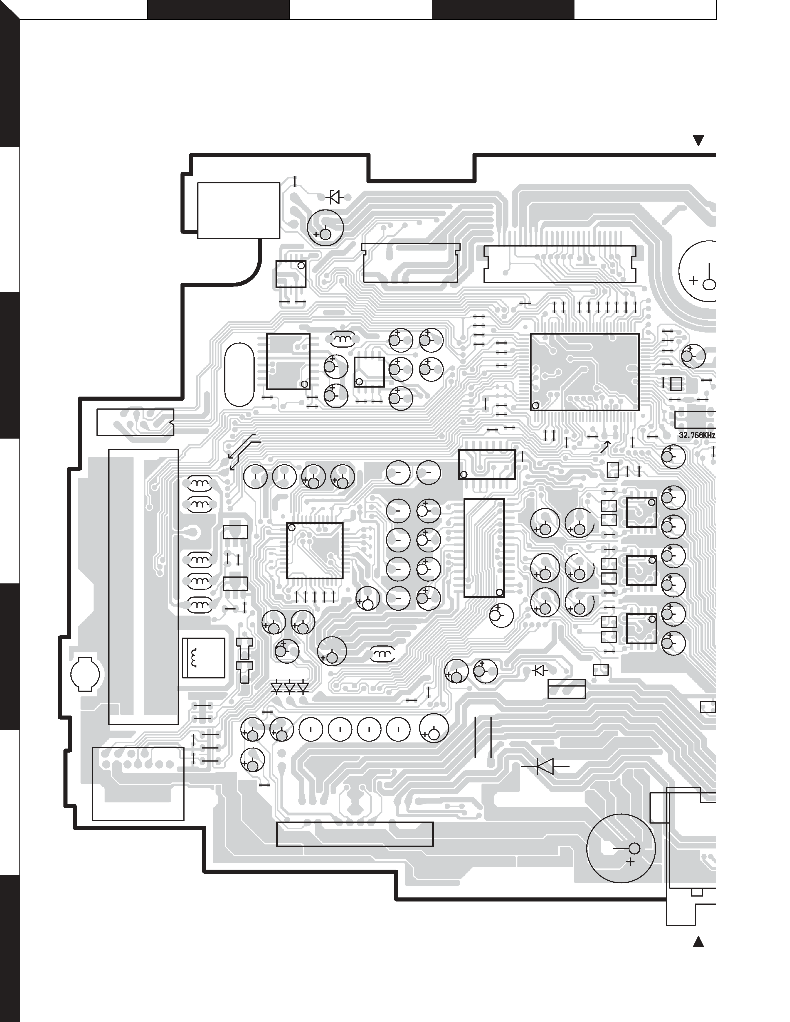
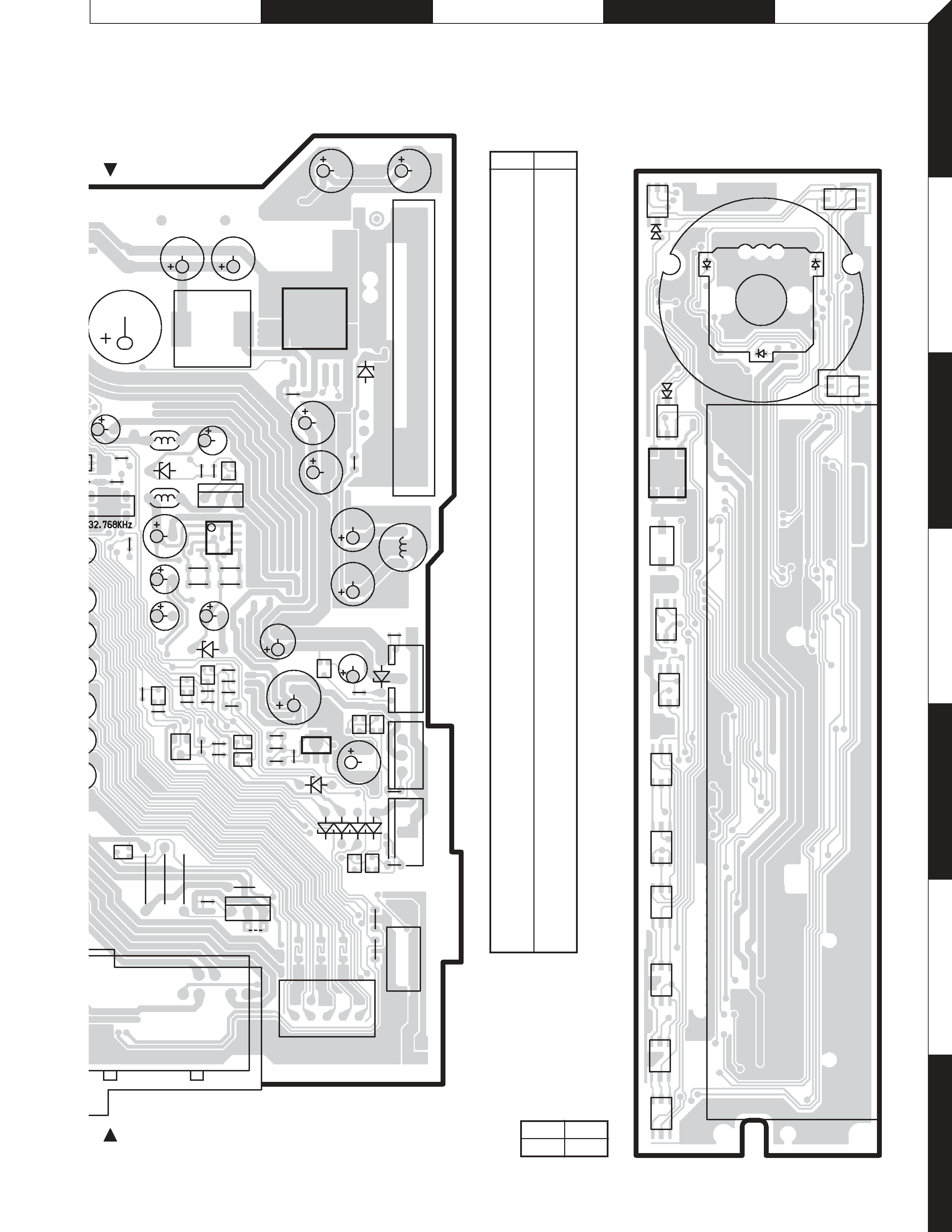
ELECTRIC UNIT X25-9172-71 (J74-1309-12)
Q9
PC BOARD (COMPONENT SIDE VIEW)
Refer to the schematic diagram for the values of resistors and capacitors.
KDC-M907
5
J
I
H
G
F
1
2
3
4
5
6
7
1
2
4
3
AM
FM
RST
AU
D
1/5
2/6
3/7
4/8
SRC
TI
ANG
D7
D5
D6
IC3
S4
S7
S6
S13
S12
S11
S9
S10
S8
S1
S3
S2
S5
S15
ED1
SWITCH UNIT X16-1602-71
(J74-1311-12)
13
41
5
1
6
1
8
H
R5
R14
R15
R16
R8
R7
C7
R33
R37
R136
R135
C26
C27
C25
C28
R43
R44
R40
R39
R2
R6
C4
C37
C38
C40
C42
R28
R36
R38
R35
R17
X2
W5
X1
Hz
C58
L2
R47
C14
B
E
B
E
B
E
B
E
E
B
E
B
E
B
E
B
E
B
B
E
BE
B
E
1
45
8
15
I
G
O
B
E
R42
R41
L5
C97
C98
C99
C95
C96
C100
9
C23
C33
C32
C5
C29
C44
C22
C3
C24
C6
C16
C21
C10
C11
C18
C8
L3
L1
R46
R27
C12
C13
C200
L4
J1/L1
5V
E
B
E
B
E
B
E
B
B
E
1
1
1
8
16
9
10
6
5
4
1
6
IC3
Q4
Q2
Q5
Q32
Q31
Q30
Q11
Q16
Q7
Q6
Q12
Q23
Q29
IC7
IC6
A1
Q1
Q8
Q13
J1
Q15
Q24
D16
D15
D6
D3
D9
D8
D7
D17
D18
CN2
CN1
X25-9172-71
Ref. No. Address
IC1
3E
IC2
4C
IC3
5G
IC4
6C
IC5
4D
IC6
2G
IC7
4F
IC9
4D
IC10
3C
IC11
4E
IC12
4E
IC13
5E
IC14
3B
IC15
2C
Q1
4G
Q2
4G
Q3
4E
Q4
5F
Q5
5F
Q6
5G
Q7
5G
Q8
5G
Q9
2B
Q11
6G
Q12
6G
Q13
5G
Q15
3F
Q16
3F
Q25
5D
Q28
5E
Q29
5F
Q30
4F
Q31
4F
Q32
4F
Q38
4E
Q39
5E
Q40
4E
Q41
4E
Q42
5E
Q43
5E
Q46
5B
Q48
4B
X16-1602-71
Ref. No. Address
IC3
3I