
KAC-PS501F
© B64-1444-00 (EM)
4-CHANNEL POWER AMPLIFIER
INSTRUCTION MANUAL
2 English
Safety precautions
Installation procedure
Since there are large variety of settings and
connections possible according to applications,
read the instruction manual well to select the
proper setting and connection.
1. Remove the ignition key and disconnect the
negative - terminal of the battery to
prevent short circuits.
2. Set the unit according to the intended usage.
3. Connect the input and output cables of the
units.
4. Connect the speaker cables.
5. Connect the power cable, power control
cable and grounding cable following this
order.
6. Install the unit in the car.
7. Connect the negative - terminal of the
battery.
· Be sure to turn the power off before
changing the setting of any switch.
· If the fuse blows, check cables for shorts,
then replace the fuse with one of the same
rating.
· Check that no unconnected cables or
connectors are touching the car body. Do
not remove caps from unconnected cables
or connectors to prevent short circuits.
· Connect the speaker cables to appropriate
speaker connectors separately. Sharing the
negative cable of the speaker or grounding
speaker cables to the metal body of the car
can cause this unit to fail.
· After installation, check that the brake
lamps, winkers, and wipers work properly.
2CAUTION
To prevent injury or fire, take the following
precautions:
· When extending the ignition, battery, or
ground cables, make sure to use automotive-
grade cables or other cables with a 10 mm
2
(AWG8) [5 mm
2 (AWG10)
× 2] or more to
prevent cable deterioration and damage to
the cable coating.
· To prevent a short circuit, never put or leave
any metallic objects (such as coins or metal
tools) inside the unit.
· If the unit starts to emit smoke or strange
smells, turn off the power immediately and
consult your Kenwood dealer.
· Do not touch the unit during use because the
surface of the unit becomes hot and may
cause burns if touched.
To prevent damage to the machine, take the
following precautions:
· Be sure the unit is connected to a 12V DC
power supply with a negative ground
connection.
· Do not open the top or bottom covers of the
unit.
· Do not install the unit in a spot exposed to
direct sunlight or excessive heat or humidity.
Also avoid places with too much dust or the
possibility of water splashing.
· When replacing a fuse, only use a new one
with the prescribed rating. Using a fuse with
the wrong rating may cause your unit to
malfunction.
· To prevent a short circuit when replacing a
fuse, first disconnect the wiring harness.
· If you experience problems during
installation, consult your Kenwood dealer.
· If the unit does not seem to be working right,
consult your Kenwood dealer.
Cleaning the unit
If the front panel gets dirty, turn off the power
and wipe the panel with a dry silicon cloth or
soft cloth.
Do not wipe the panel with a hard cloth or a
cloth dampened by volatile solvents such as
paint thinner and alcohol. They can scratch the
surface of the panel and/or cause the indicator
letters to peel off.
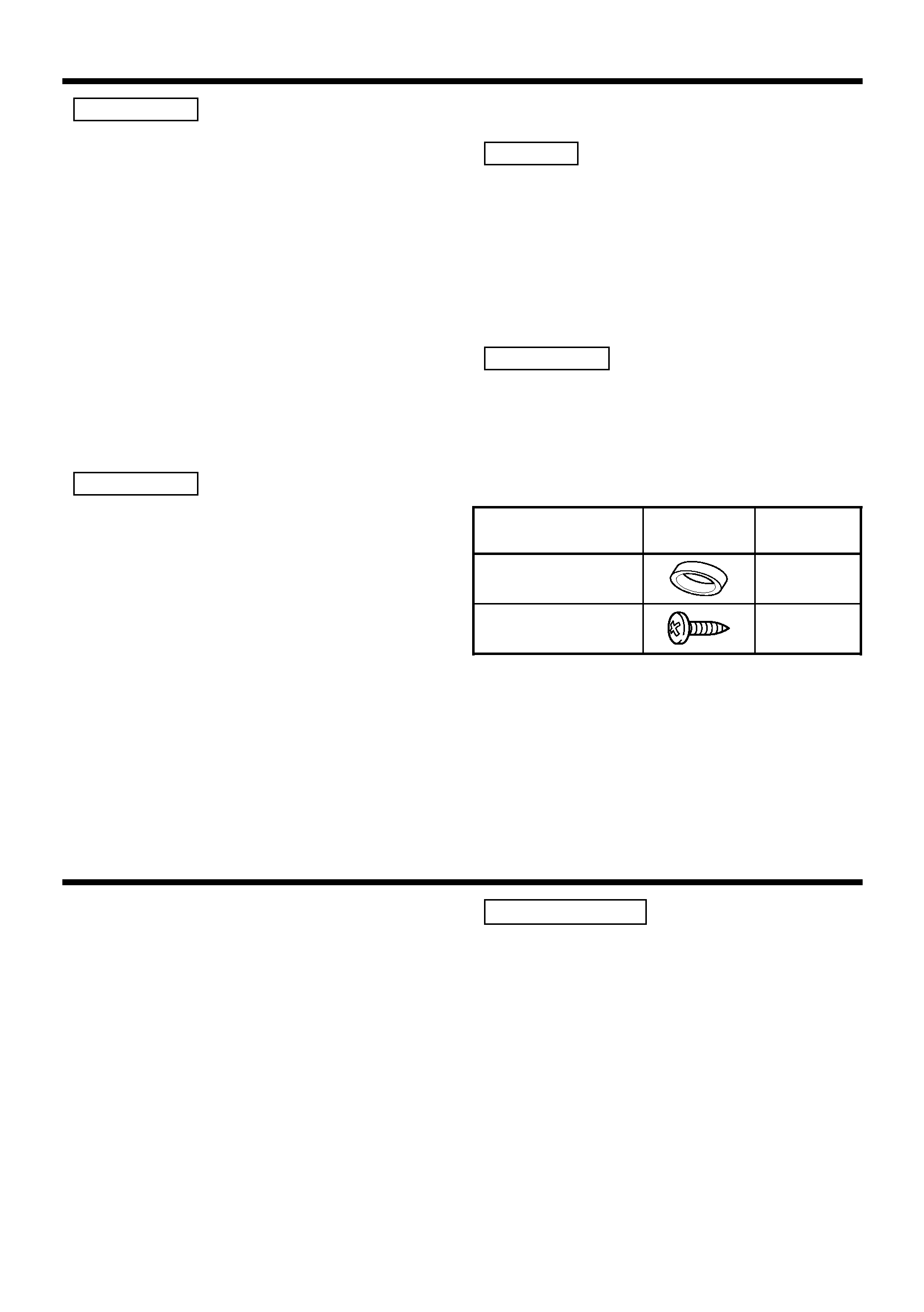
Accessories
2CAUTION
NOTE
2CAUTION
2WARNING
Part name
Number of
Items
External
View
Terminal cover
(Power terminal)
1
Self-tapping screws
(ø5
× 18 mm)
4
English
3
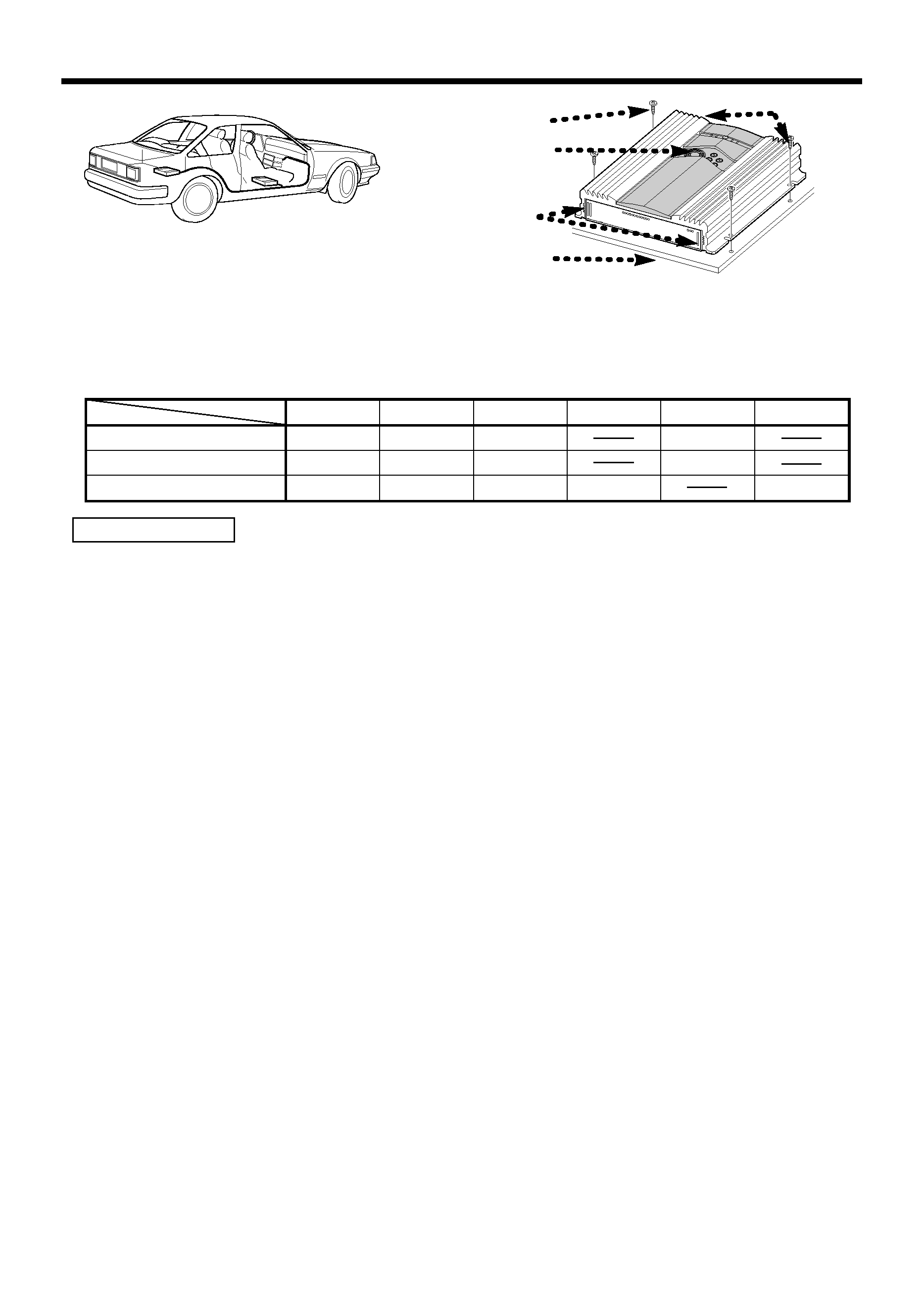
Installation
· Since the power amplifier has no parts which require operation, it can be installed at a position
away from the driver's seat without any hindrances.
As generally accepted positions for its installation, places such as inside the trunk, etc. can be
considered.
· Use the extension cables. (Optional.)
· Do not install the unit under the carpet. Otherwise heat build-up occurs and the unit may be
damaged.
· Install this unit in a location which allows heat to easily dissipate.
Once installed, do not place any object on top of the unit.
· The surface temperature of the amplifier will become hot during use. Install the amplifier in a
place where people, resins, and other substances that are sensitive to heat will not come into
contact with it.
· This unit has cooling fans to decrease the internal temperature. Be careful not to block the
cooling fan openings when installing the unit. Blocking these openings will inhibit the cooling of
the internal temperature and result in malfunction.
· When making a hole under a seat, inside the trunk, or somewhere else in the vehicle, check
that there is nothing hazardous on the opposite side such as a gasoline tank, brake pipe, or
wiring harness, and be careful not to cause scratches or other damage.
· Do not install near the dashboard, rear tray, or air bag safety parts.
· The installation to the vehicle should securely fasten the unit to a place in which it will not
obstruct driving. If the unit comes off due to a shock and hits a person or safety part, it may
cause injury or an accident.
· After installing the unit, check to make sure that electrical equipment such as the brake lamps,
turn signal lamps and windshield wipers operate normally.
2CAUTION
,,,,,,,,,,,,,,,,,,,,,,,,,,,,,,,
,,,,,,,,,,,,,,,,,,,,,,,,,,,,,,,
,,,,,,,,,,,,,,,,,,,,,,,,,,,,,,,
,,,,,,,,,,,,,,,,,,,,,,,,,,,,,,,
,,,,,,,,,,,,,,,,,,,,,,,,,,,,,,,
,,,,,,,,,,,,,,,,,,,,,,,,,,,,,,,
,,,,,,,,,,,,,,,,,,,,,,,,,,,,,,,
,,,,,,,,,,,,,,,,,,,,,,,,,,,,,,,
,,,,,,,,,,,,,,,,,,,,,,,,,,,,,,,
,,,,,,,,,,,,,,,,,,,,,,,,,,,,,,,
,,,,,,,,,,,,,,,,,,,,,,,,,,,,,,,
,,,,,,,,,,,,,,,,,,,,,,,,,,,,,,,
,,,,,,,,,,,,,,,,,,,,,,,,,,,,,,,
,,,,,,,,,,,,,,,,,,,,,,,,,,,,,,,
,,,,,,,,,,,,,,,,,,,,,,,,,,,,,,,
,,,,,,,,,,,,,,,,,,,,,,,,,,,,,,,
,,,,,,,,,,,,,,,,,,,,,,,,,,,,,,,
,,,,,,,,,,,,,,,,,,,,,,,,,,,,,,,
,,,,,,,,,,,,,,,,,,,,,,,,,,,,,,,
,,,,,,,,,,,,,,,,,,,,,,,,,,,,,,,
,,,,,,,,,,,,,,,,,,,,,,,,,,,,,,,
,,,,,,,,,,,,,,,,,,,,,,,,,,,,,,,
,,,,,,,,,,,,,,,,,,,,,,,,,,,,,,,
,,,,,,,,,,,,,,,,,,,,,,,,,,,,,,,
,,,,,,,,,,,,,,,,,,,,,,,,,,,,,,,
,,,,,,,,,,,,,,,,,,,,,,,,,,,,,,,
,,,,,,,,,,,,,,,,,,,,,,,,,,,,,,,
,,,,,,,,,,,,,,,,,,,,,,,,,,,,,,,
,,,,,,,,,,,,,,,,,,,,,,,,,,,,,,,,,,,,,,,,,,,,,,,
,,,,,,,,,,,,,,,,,,,,,,,,,,,,,,,,,,,,,,,,,,,,,,,
,,,,,,,,,,,,,,,,,,,,,,,,,,,,,,,,,,,,,,,,,,,,,,,
,,,,,,,,,,,,,,,,,,,,,,,,,,,,,,,,,,,,,,,,,,,,,,,
,,,,,,,,,,,,,,,,,,,,,,,,,,,,,,,,,,,,,,,,,,,,,,,
,,,,,,,,,,,,,,,,,,,,,,,,,,,,,,,,,,,,,,,,,,,,,,,
,,,,,,,,,,,,,,,,,,,,,,,,,,,,,,,,,,,,,,,,,,,,,,,
,,,,,,,,,,,,,,,,,,,,,,,,,,,,,,,,,,,,,,,,,,,,,,,
,,,,,,,,,,,,,,,,,,,,,,,,,,,,,,,,,,,,,,,,,,,,,,,
,,,,,,,,,,,,,,,,,,,,,,,,,,,,,,,,,,,,,,,,,,,,,,,
,,,,,,,,,,,,,,,,,,,,,,,,,,,,,,,,,,,,,,,,,,,,,,,
,,,,,,,,,,,,,,,,,,,,,,,,,,,,,,,,,,,,,,,,,,,,,,,
,,,,,,,,,,,,,,,,,,,,,,,,,,,,,,,,,,,,,,,,,,,,,,,
,,,,,,,,,,,,,,,,,,,,,,,,,,,,,,,,,,,,,,,,,,,,,,,
,,,,,,,,,,,,,,,,,,,,,,,,,,,,,,,,,,,,,,,,,,,,,,,
Installation board, etc.
(thickness : 15 mm or more)
Self-tapping screw
CA-2SL
CA-12SL
CA-22SL
CA-52SL
RCA cable
CA-3WL
CA-13WL
CA-23WL
CA-53WL
RCA cable (ø7mm)
CA-5W
CA-15W
CA-25W
CA-45W
CA-65W
RCA cable (ø12mm)
0.5m
1m
2m
4m
5m
6m
Type
Length
Cooling fan
Air inlet
Exhaust outlet
4 English
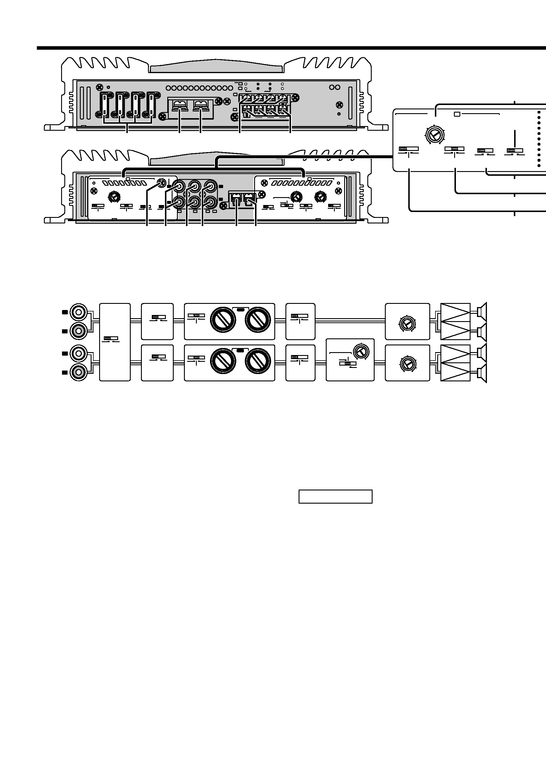
Controls
This is a 4 channel amplifier including 2 stereo amplifiers in a body. One amplifier is referred to
as amplifier A and the other is amplifier B. This unit is compatible with a large variety of
systems by combining the switches and functions described in the following.
L
R
L
R
LINE IN
P.CON
EXT.AMP.CONT.
GND
MONO
LINE OUT
25Hz
15Hz
INFRASONIC
FILTER
OPERATION
OFF
0.2
0.5
5
1
2
3
4
B
B
A
A
+
(MAX)
(MIN)
25Hz
15Hz
INFRASONIC
FREQ (Hz)
FREQ (Hz)
OFF
LPF
OFF
HPF
MONO
STEREO
FILTER
LPF
OFF
HPF
OPERATION
MONO
STEREO
B.M.S.
B.M.S.
FREQ(Hz)
B.M.S.
(
+6)
CLOSE
OPEN/ B.M.S.
(REMOTE)
INPUT SELECT
A
AB
CONTROL
INPUT SENSITIVITY(V)
0.2
0.5
5
1
2
3
4
100
50
80
(MAX)
(MIN)
INPUT SENSITIVITY(V)
A
CONTROL B
LEFT
BRIDGED
RIGHT
SPEAKER OUTPUT
FUSE(20A
×4)
BATT.
GND
B
B
A
A
20
20
20
20
$
%
*
@
25Hz
15Hz
INFRASONIC
FILTER
OPERATION
OFF
0.2
0.5
5
1
2
3
4
(MAX)
(MIN)
FREQ (Hz)
LPF
OFF
HPF
MONO
STEREO
INPUT SELECT
A
AB
CONTROL
INPUT SENSITIVITY(V)
A
#
1
4
2 3
78 9
6
0!
5
1
Fuse (20 A
× 4)
2
Battery terminal
3
Ground terminal
4
Amplifier A speaker output
terminals
5
Amplifier B speaker output
terminals
ySPEAKER OUTPUT terminals
· Stereo Connections:
When you wish to use the unit as a stereo
amplifier, stereo connections are used.
The speakers to be connected should
have an impedance of 2
or greater.
When multiple speakers are to be
connected, ensure that the combined
impedance is 2
or greater for each
channel.
· Bridged Connections:
When you wish to use the unit as a high-
output monaural amplifier, bridged
connections are used. (Make connections
to the LEFT channel (+) and the RIGHT
channel (-) SPEAKER OUTPUT terminals.)
The speakers to be connected should
have an impedance of 4
or greater.
When multiple speakers are to be
connected, ensure that the combined
impedance is 4
or greater.
The rated input of the speakers should be
no less than the maximum output of the
amplifier. Otherwise malfunction may
result.
6
RCA cable ground lead terminal
7
Amplifier A LINE IN terminal
8
Amplifier B LINE IN terminal
9
LINE OUT terminal
These jacks output respectively the signals
input to amplifiers A and B. They always
output the stereo signals regardless of the
position of the OPERATION switch.
0
Power control terminal
!
EXT.AMP.CONT. (external
amplifier control) terminal
This controls the B.M.S. (See P.6).
2CAUTION
L
R
L
R
A
B
LO PASS
50
50
200
200
HI PASS
LO PASS
50
50
200
200
HI PASS
A
B
25Hz
15Hz
INFRASONIC
FILTER
OPERATION
OFF
25Hz
15Hz
INFRASONIC
FREQ (Hz)
FREQ (Hz)
OFF
LPF
OFF
HPF
MONO
STEREO
FILTER
LPF
OFF
HPF
OPERATION
MONO
STEREO
INPUT SELECT
A
AB
0.2
0.5
5
1
2
3
4
(MAX)
(MIN)
INPUT SENSITIVITY(V)
0.2
0.5
5
1
2
3
4
(MAX)
(MIN)
INPUT SENSITIVITY(V)
@#
$%
&
^
*
#1
#2
B.M.S.
B.M.S.
FREQ(Hz)
B.M.S.
(
+6)
CLOSE
OPEN/ B.M.S.
(REMOTE)
100
50
80
#1 When FILTER is set to LPF, the sound is monaural (L+R).
#2 When INFRASONIC is set to 15Hz or 25Hz, the sound is monaural (L+R).
* Note that if OPERATION is set to MONO, Lch is still monaural.
Block diagram
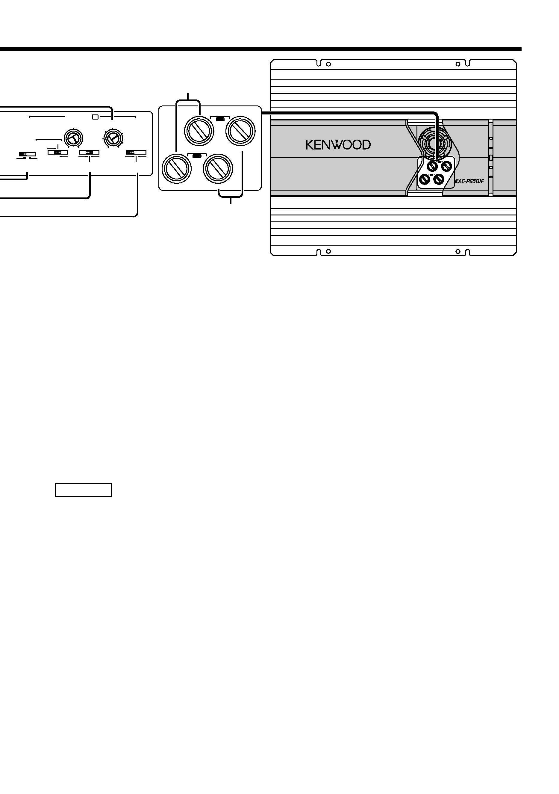
@
INPUT SELECTOR switch
This switch selects the input method of the
signals to be amplified by amplifiers A and
B.
· A B position:
Amplifies both of the signals input to
amplifiers A and B.
· A position:
Amplifies only signal input amplifier A with
both amplifiers A and B.
#
INPUT SENSITIVITY control
Adjust this control according to the pre-out
level of the centre unit connected to this
amplifier.
The sensitivities of amplifiers A and B can
be adjusted independently regardless of the
position of the input selector switch.
Refer to "Specifications" on the centre
unit's instruction manual about the pre-out
level.
$
OPERATION switch
The amplification methods of the signals
input to amplifiers A and B can be selected
independently according to the setting of
this switch.
· STEREO position:
The amplifier can be used as a stereo
amplifier.
· MONO (Lch) position:
Amplifies the signal input from the left side
only. Set to this position and make bridged
connections to use as a high-power
monaural amplifier. (The input right signal is
not output.)
%
FILTER switch
This switch allows to apply high-pass or
low-pass filtering to the speaker outputs.
· HPF (High-Pass Filter) position:
The filter outputs the band of higher
frequencies than the frequency set with the
HPF FREQUENCY control.
· OFF position:
The entire bandwidth is output without
filtering.
· LPF (Low-Pass Filter) position:
The filter outputs the band of lower
frequencies than the frequency set with the
LPF FREQUENCY control.
The speaker output is automatically turned
monaural (L+R) and the bass boost function
is activated.
^
HPF FREQUENCY control
Sets the cutoff frequency when the FILTER
switch is set to HPF.
&
LPF FREQUENCY control
Sets the cutoff frequency when the FILTER
switch is set to LPF.
*
INFRASONIC FILTER switch
When this switch is set to 15 Hz or 25 Hz,
frequencies below the setting value will be
cut. This serves to get rid of unwanted
vibrations that do not result in sound and
improves the speakers' ability to reproduce
sound. Note that the speaker output will
automatically be set for monaural (L+R)
sound.
NOTE
English
5
AIR
INDUCTION
LO PASS
50
50
200
200
HI PASS
LO PASS
50
50
200
200
HI PASS
FILTER
FREQUENCY
A
B
POWER
COOLING FAN
OPERATION/PROTECTION
OPEN/CLOSE
LOW VOLTAGE
B.M.S.
4/3/2 CHANNEL POWER AMPLIFIER
&
^
LO PASS
50
50
200
200
HI PASS
LO PASS
50
50
200
200
HI PASS
FILTER
FREQUENCY
A
B
25Hz
15Hz
INFRASONIC
FREQ (Hz)
OFF
FILTER
LPF
OFF
HPF
OPERATION
MONO
STEREO
B.M.S.
B.M.S.
FREQ(Hz)
B.M.S.
(
+6)
CLOSE
OPEN/ B.M.S.
(REMOTE)
0.2
0.5
5
1
2
3
4
100
50
80
(MAX)
(MIN)
INPUT SENSITIVITY(V)
CONTROL B