SERVICE MANUAL
DVD VIDEO PLAYER
No.A0006
Apr. 2001
COPYRIGHT
2001 VICTOR COMPANY OF JAPAN, LTD.
XV-S40BK / XV-S42SL
XV-E100SL
XV-S40BK/XV-S42SL
XV-E100SL
Area Suffix (XV-S42SL)
B ------------------------- U.K.
E --- Continental Europe
EN ---- Northern Europe
EV ------ Eastern Europe
Area Suffix(XV-E100SL)
B ------------------------- U.K.
E --- Continental Europe
EN ---- Northern Europe
EV ------ Eastern Europe
EE -- Russian Federation
B ------------------------- U.K.
E --- Continental Europe
EN ---- Northern Europe
Area Suffix (XV-S40BK)
This service manual is printed on 100% recycled paper.
Contents
Safety precautions ------------------------ 1-2
Preventing static electricity ------------- 1-3
Precautions for service ------------------ 1-4
Important for laser products ----------- 1-5
Disassembly method -------------------- 1-6
Adjustment method ---------------------- 1-15
Description of major ICs ---------------- 1-21
Model
XV-S40BK
XV-S42SL
XV-E100SL
Body color
Black
Silver
Silver
Each difference point
In regard with component parts appearing on the silk-screen printed side (parts side) of
the PWB diagrams, the parts that are printed over with black such as the resistor (
),
diode (
) and ICP (
) or identified by the "
" mark nearby are critical for safety.
When replacing them, be sure to use the parts of the same type and rating as specified
by the manufacturer. (Except the JC version)
XV-S40BK/XV-S42SL/XV-E100SL
1-2
1. This design of this product contains special hardware and many circuits and components specially
for safety purposes.
For continued protection, no changes should be made to the original design
unless authorized in writing by the manufacturer.
Replacement parts must be identical to those
used in the original circuits.
Services should be performed by qualified personnel only.
2. Alterations of the design or circuitry of the product should not be made.
Any design alterations of
the product should not be made.
Any design alterations or additions will
void the
warranty
and will further relieve the manufacture of responsibility for personal injury or property damage
resulting therefrom.
3. Many electrical and mechanical parts in the products have special safety-related characteristics.
These characteristics are often not evident from visual inspection nor can the protection afforded
by them necessarily be obtained by using replacement components rated for higher voltage,
wattage, etc.
Replacement parts which have these special safety characteristics are identified in
the Parts List of Service Manual.
Electrical components having such features are identified by
shading on the schematics and by (
) on the Parts List in the Service Manual.
The use of a
substitute replacement which does not have the same safety characteristics as the recommended
replacement parts shown in the Parts List of Service Manual may create shock, fire, or other
hazards.
4. The leads in the products are routed and dressed with ties, clamps, tubings, barriers and the
like to be separated from live parts, high temperature parts, moving parts and/or sharp edges
for the prevention of electric shock and fire hazard.
When service is required, the original lead
routing and dress should be observed, and it should be confirmed that they have been returned
to normal, after reassembling.
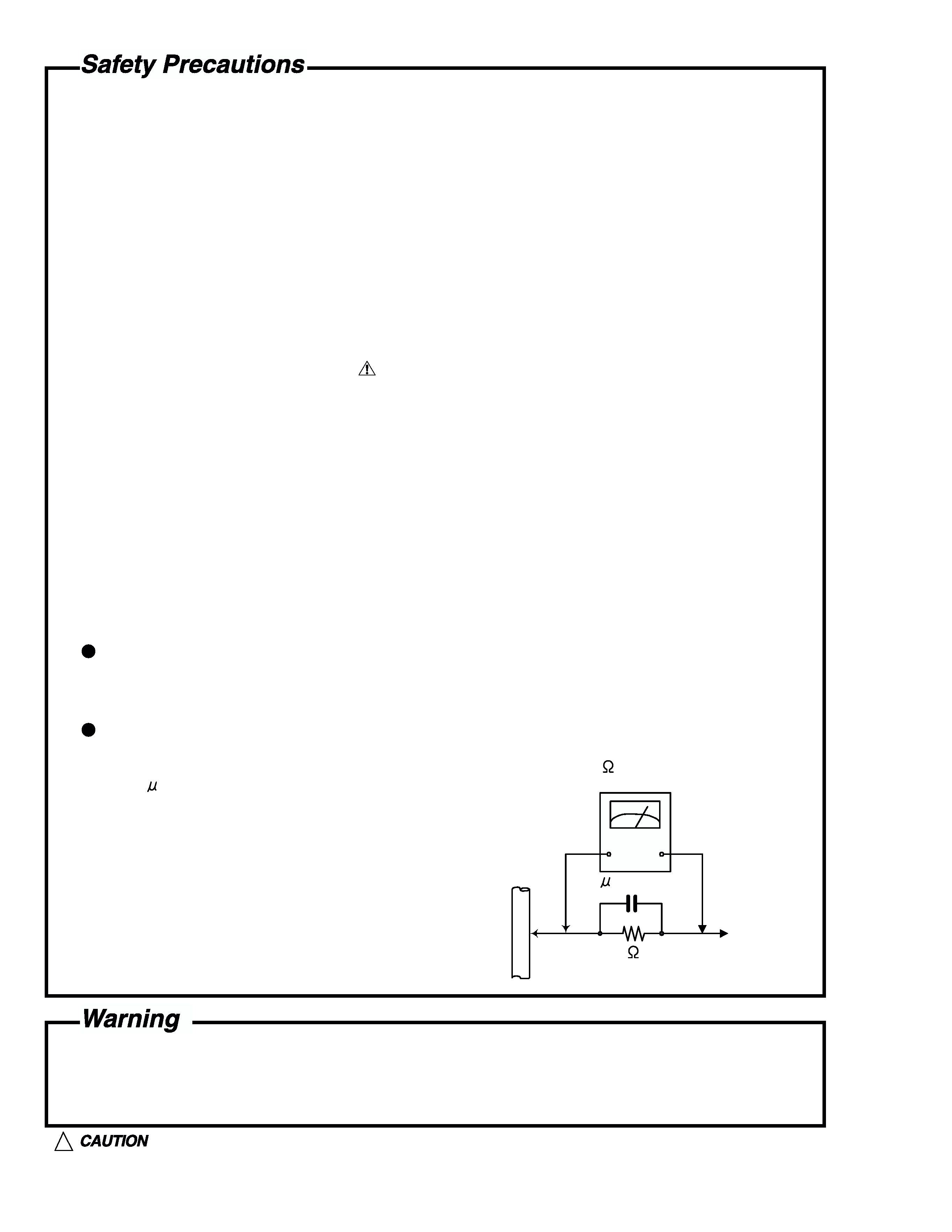
5. Leakage current check (Electrical shock hazard testing)
After reassembling the product, always perform an isolation check on the exposed metal parts of
the product (antenna terminals, knobs, metal cabinet, screw heads, headphone jack, control
shafts, etc.) to be sure the product is safe to operate without danger of electrical shock.
Do not use a line isolation transformer during this check.
Plug the AC line cord directly into the AC outlet.
Using a "Leakage Current Tester", measure
the leakage
current from each exposed metal parts of the cabinet , particularly any exposed
metal part having a return path to the chassis, to a known good earth ground. Any leakage
current must not exceed 0.5mA AC (r.m.s.)
Alternate check method
Plug the AC line cord directly into the AC outlet.
Use an AC voltmeter having, 1,000 ohms
per volt or more sensitivity in the following manner. Connect a 1,500
10W resistor paralleled by
a 0.15 F AC-type capacitor between an exposed
metal part and a known good earth ground.
Measure the AC voltage across the resistor with the
AC voltmeter.
Move the
resistor
connection
to each exposed
metal part, particularly any exposed metal part
having a return path to the chassis, and measure
the AC voltage across the resistor. Now, reverse
the plug in the AC outlet and repeat each
measurement. voltage measured Any must
not
exceed 0.75 V AC (r.m.s.). This corresponds to 0.5
1. This equipment has been designed and manufactured to meet international safety standards.
2. It is the legal responsibility of the repairer to ensure that these safety standards are maintained.
3. Repairs must be made in accordance with the relevant safety standards.
4. It is essential that safety critical components are replaced by approved parts.
5. If mains voltage selector is provided, check setting for local voltage.
Good earth ground
Place this
probe on
each exposed
metal part.
AC VOLTMETER
(Having 1000
ohms/volts,
or more sensitivity)
1500
10W
0.15 F AC TYPE
!
Burrs formed during molding may be left over on some parts of the chassis. Therefore,
pay attention to such burrs in the case of preforming repair of this system.
XV-S40BK/XV-S42SL/XV-E100SL
1-3
Preventing static electricity
Electrostatic discharge (ESD), which occurs when static electricity stored in the body, fabric, etc. is discharged,
can destroy the laser diode in the traverse unit (optical pickup). Take care to prevent this when performing repairs.
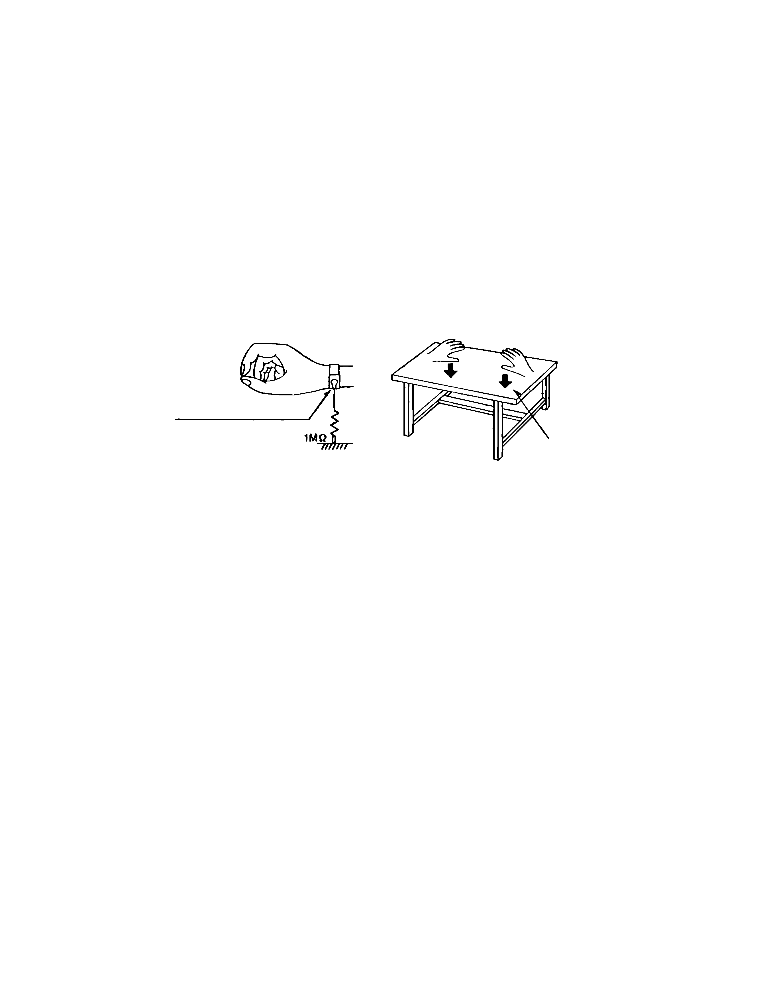
1.1. Grounding to prevent damage by static electricity
Static electricity in the work area can destroy the optical pickup (laser diode) in devices such as DVD players.
Be careful to use proper grounding in the area where repairs are being performed.
1.1.1. Ground the workbench
1. Ground the workbench by laying conductive material (such as a conductive sheet) or an iron plate over
it before placing the traverse unit (optical pickup) on it.
1.1.2. Ground yourself
1. Use an anti-static wrist strap to release any static electricity built up in your body.
1.1.3. Handling the optical pickup
1. In order to maintain quality during transport and before installation, both sides of the laser diode on the
replacement optical pickup are shorted. After replacement, return the shorted parts to their original condition.
(Refer to the text.)
2. Do not use a tester to check the condition of the laser diode in the optical pickup. The tester's internal power
source can easily destroy the laser diode.
1.2. Handling the traverse unit (optical pickup)
1. Do not subject the traverse unit (optical pickup) to strong shocks, as it is a sensitive, complex unit.
2. For specific details, refer to the replacement procedure in the text. Be careful not to take too long a time
when attaching it to the connector.
3. Handle the flexible cable carefully as it may break when subjected to strong force.
4. It is not possible to adjust the semi-fixed resistor that adjusts the laser power. Do not turn it
Conductive material
(conductive sheet) or iron plate
(caption)
Anti-static wrist strap
XV-S40BK/XV-S42SL/XV-E100SL
1-4
Precautions for Service
Handling of Traverse Unit and Laser Pickup
1. Do not touch any peripheral element of the pickup or the actuator.
2. The traverse unit and the pickup are precision devices and therefore must not be subjected to
strong shock.
3. Do not use a tester to examine the laser diode. (The diode can easily be destroyed by the
internal power supply of the tester.)
4. When replacing the pickup, after mounting a new pickup, remove the solder on the short land
which is provided at the center of the flexible wire to open the circuit.
6. Half-fixed resistors for laser power adjustment are adjusted in pairs at shipment to match the
characteristics of the optical block.
Do not change the setting of these half-fixed resistors for laser power adjustment.
Destruction of Traverse Unit and Laser Pickup by Static Electricity
Laser diodes are easily destroyed by static electricity charged on clothing
or the human body. Before repairing peripheral elements of the traverse
unit or pickup, be sure to take the following electrostatic protection:
1. Wear an antistatic wrist wrap.
2. With a conductive sheet or a steel plate on the workbench on which
the traverse unit or the pick up is to be repaired, ground the sheet or the plate.
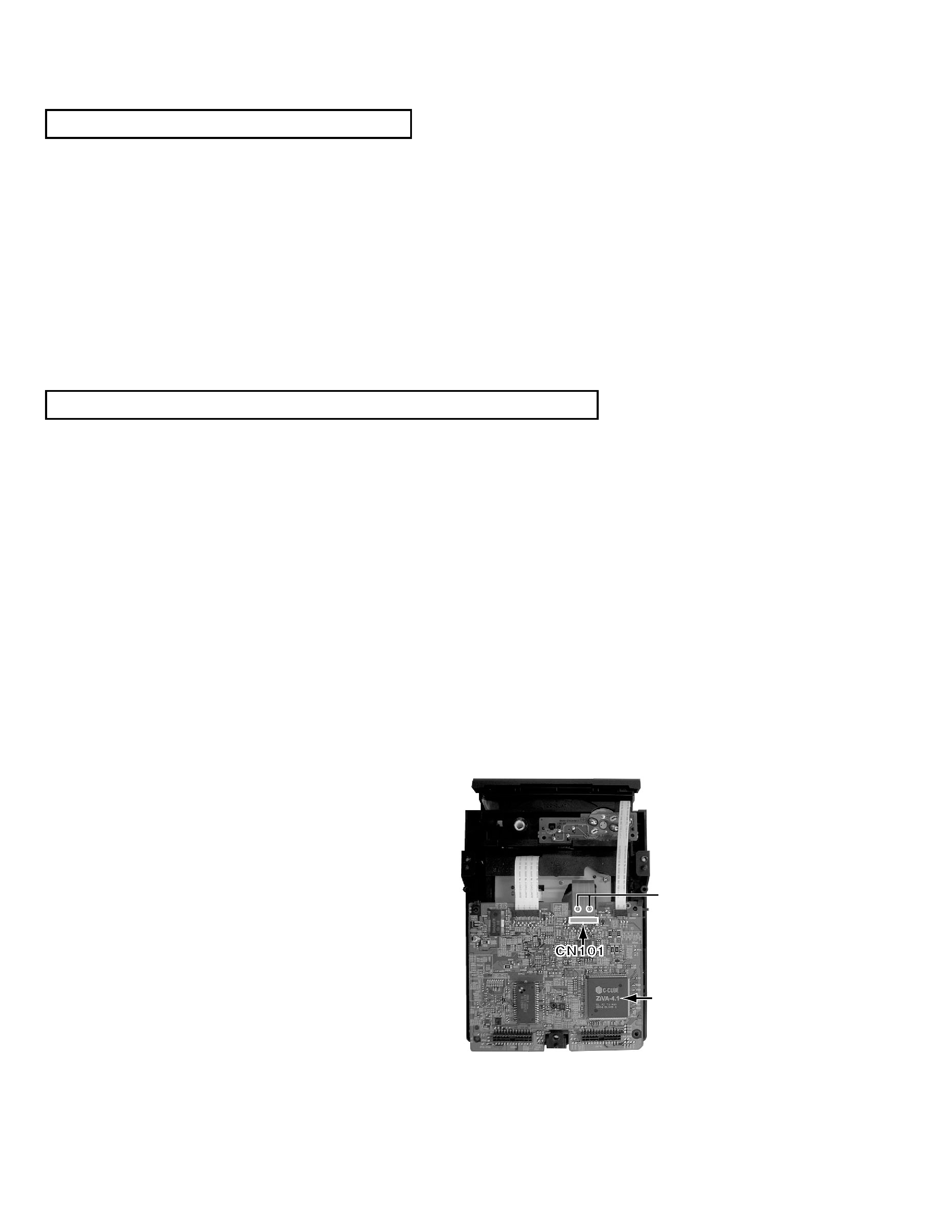
3. Pick-up's laser diode might be destroyed by static electricity, and put up solder to "Soldering part A",
please before extracting the card wire from connector (CN101).
4. Moreover, please remove solder from "Soldering part A" after inserting the card wire in connector (CN101)
at assembly.
Servo control
board
Soldering part A
Please refer to "Fig.4" of "Disassembly
method" for details.
XV-S40BK/XV-S42SL/XV-E100SL
1-5
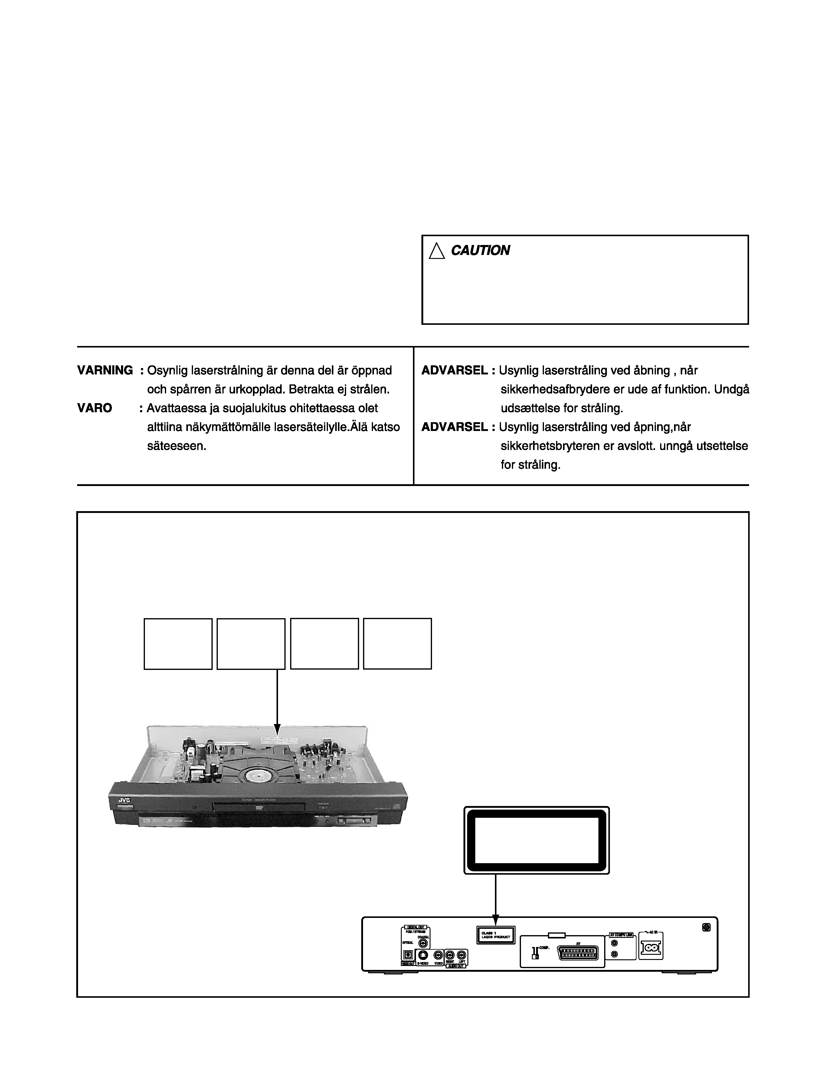
Important for Laser Products
1.CLASS 1 LASER PRODUCT
2.DANGER : Invisible laser radiation when open and inter
lock failed or defeated. Avoid direct exposure to beam.
3.CAUTION : There are no serviceable parts inside the
Laser Unit. Do not disassemble the Laser Unit. Replace
the complete Laser Unit if it malfunctions.
4.CAUTION : The compact disc player uses invisible laser
radiation and is equipped with safety switches which
prevent emission of radiation when the drawer is open and
the safety interlocks have failed or are de
feated. It is dangerous to defeat the safety switches.
5.CAUTION : If safety switches malfunction, the laser is able
to function.
6.CAUTION : Use of controls, adjustments or performance of
procedures other than those specified herein may result in
hazardous radiation exposure.
REPRODUCTION AND POSITION OF LABEL and PRINT
WARNING LABEL and PRINT
!
Please use enough caution not to
see the beam directly or touch it
in case of an adjustment or operation
check.
CLASS 1
LASER PRODUCT
CAUTION: Invisible laser
radiation when open and
interlock failed or defeated.
AVOID DIRECT EXPOSURE
TO BEAM.
(e)
ADVARSEL: Usynlig laser-
stråling ved åbning, når
sikkerhedsafbrydere er ude
af funktion. Undgå udsæt-
telse for stråling
(d)
VARNING: Osynlig laser-
strålning när denna del är
öppnad och spärren är
urkopplad.
Betrakta
ej
strålen.
(s)
VARO: Avattaessa ja suo-
jalukitus ohitettaessa olet
alttiina
näkymättömälle
lasersäteilylle. Älä katso
säteeseen.
(f)