VU-LD20U
LINE DOUBLER
Thank you for purchasing this product.
Before using your new purchase, please read this instruction manual thoroughly. And, after
reading, be sure to store this instruction manual in a safe place for future reference.
POWER
INPUT 6
S-Video
Comp
Prog. 1
Prog. 2
Prog. 3
INPUT SELECTOR
Prog. 4
Prog. 5
AVC
Prog. 6
Prog. 7
Prog. 8
Prog. 9
Prog. 10
REMOTE
SENSOR
FAROUDJA
PICTURE PLUS
LINE DOUBLER VU-LD20U
VICTOR COMPANY OF JAPAN, LIMITED
Printed in Japan
1299NFVTMEETMEE
VU-LD20U
M-871D282A3Ø
Instruction Manual
LPT0410-001A
For Customer Use:
Enter below the Serial No. which is
located on the rear of the cabinet.
Retain this information for future
reference.
Model No. VU-LD20U
Serial No.
2
CAUTION: TO REDUCE THE RISK OF ELECTRIC SHOCK,
DO NOT REMOVE COVER (OR BACK).
NO USER-SERVICEABLE PARTS INSIDE.
REFER SERVICING TO QUALIFIED SERVICE PERSONNEL.
The lightning flash with arrowhead symbol, within an equilateral triangle, is intended to alert the user to
the presence of uninsulated "dangerous voltage" within the product's enclosure that may be of sufficient
magnitude to constitute a risk of electric shock to persons.
The exclamation point within an equilateral triangle is intended to alert the user to the presence of impor-
tant operating and maintenance (servicing) instructions in the literature accompanying the product.
IMPORTANT:
RECORDING OF COPYRIGHTED TELEVISION PROGRAMS MAY VIOLATE COPYRIGHT LAW.
WARNING:
TO REDUCE THE RISK OF FIRE OR ELECTRIC SHOCK, DO NOT EXPOSE THIS PRODUCT TO RAIN OR MOISTURE.
CAUTION:
TO PREVENT ELECTRIC SHOCK HAZARD, DO NOT USE THIS (POLARIZED) PLUG WITH AN EXTENSION CORD, RECEP-
TACLE OR OTHER OUTLET UNLESS THE BLADES CAN BE FULLY INSERTED TO PREVENT BLADE EXPOSURE.
CAUTION
RISK OF ELECTRIC SHOCK
DO NOT OPEN
DANGER D'ELECTROCUTION
NE PAS OUVRIR
La flèche symbolisant le tonnerre à l'intérieur d'un triangle équilatéral a pour but de prévenir
l'utilisateur de la présence d'une "tension dangereuse" non isolée se trouvant à l'intérieur du
dispositif; elle est d'une magnitude suffisante pour constituer un risque de décharge électrique.
Le point d'exclamation à l'intérieur d'un triangle équilatéral a pour but de prévenir l'utilisateur de la
présence d'importantes instructions concernant l'entretien et le un fonctionnement indiquées dans
les textes accompagnant le dispositif.
MISE EN GARDE :
AFIN DE REDUIRE LES RISQUES D'INCENDIE OU DE DECHARGE ELECTRIQUE, NE PAS EXPOSER CET
APPAREIL A LA PLUIE OU A L'HUMIDITE.
ATTENTION :
AFIN DE REDUIRE LES RISQUES DE DECHARGE ELECTRIQUE, NE PAS UTILISER LA FICHE (POLARISEE) DE
CET APPAREIL AVEC UN PROLONGATEUR, UNE PRISE OU UNE AUTRE PRISE DE COURANT SAUF SI CES
LAMES PEUVENT ETRE INSEREES A FOND.
REMARQUE :
ETANT DONNE QUE CE PROJECTEUR EST UN APPAREIL QUI DOIT ETRE BRANCHE, LA PRISE MURALE DOIT
ETRE INSTALLEE PRES DU PROJECTEUR ET DOIT ETRE FACILEMENT ACCESSIBLE.
AVERTISSEMENT: POUR ELIMINER TOUT RISQUE D'ELECTROCUTION NE PAS
OUVRIR LE COUVERCLE (OU LA PARTIE ARRIERE).
AUCUNE PIECE PEPARABLE PAR L'UTILISATEUR NE SE TROUVE A L'INTERIEUR.
POUR TOUTE INTERVENTION D'ENTRETIEN OU DE REPARATION SE CONFIER
AUX TECHNICIENS QUALIFIES.
AVERTISSEMENT

3
FEATURES
Stunning image quality through highly accurate signal processing
Our original three-dimension Y/C separation circuit has been employed together with the image processing circuit made
by Faroudja in the decoder section, the line doubler section, and the bandwidth expander section. Consistent signal
processing with high accuracy from input to output provides stunning image quality.
-
Line doubler section
Signals from the decoder section are progressively processed in the line doubler section. Faroudja's unique motion
algorithm rids jaggies and flickers from images by converting film images of 30 frames per second into 24 frames per
second and applying total still image processing. Reproduction through double the number of scanning lines realizes
natural progressive processing with higher accuracy and less missing information.
-
NTSC color decoder section
Faroudja's most reliable decoder for 10-bit processing and Analog Device's high performance AD converter jointly
offer highly accurate AD conversion. In addition, Faroudja's original chroma band expansion circuit provides film-like
images of high definition, greatly enhancing color transition, trangent and resolution.
-
Bandwidth expander section
In the bandwidth expander section, signals are refined to obtain higher image quality after the line doubling process-
ing. Bandwidth of Y (luminance) signal is doubled through the non-liner processing. Expanded bandwidth increases
image detail, improves trangent and enhances sharpness of images, achieving dramatic development in video image
quality and striking beauty and impression.
-
Y/C separation circuit section
Our original three-dimension filter correctly separates signals having motion images as well as signals having station-
ary images, considerably reducing cross-color and dot interference.
Selector function to connect 18 video sources at the maximum
Selectable inputs of three types, VIDEO IN, S-VIDEO IN and COMPONENT IN, allow 18 video sources at the maximum
to be connected depending on combination.
Various image quality adjustments
Various image quality adjustments, from basic adjustments of sharpness, contrast, etc. to advanced adjustments such as
black level extension adjustment, are available and offer a possible use as an equalizer. These adjustments can be
memorized in every program. Images are easily reproduced according to the preprogrammed adjustments just by switching
the programs depending on image materials.
The Faroudja name is the registered trademark of Faroudja, Inc. in the United States.
CONTENTS
IMPORTANT SAFEGUARDS ....................................................................................... 4, 5
OVERVIEW OF THE PRODUCT .................................................................................. 6, 7
Front panel ............................................................................................................................. 6
Rear panel ............................................................................................................................. 7
OVERVIEW OF THE REMOTE CONTROL .................................................................. 8, 9
Battery installation ................................................................................................................. 9
PREPARATION .............................................................................................................. 10
Preparing for operation ........................................................................................................ 10
System configuration ........................................................................................................... 10
CONNECTIONS ........................................................................................................ 11-14
Connection with a D-ILA, LCD projector .............................................................................. 11
Connection with a Projector ................................................................................................. 12
Connection with a VCR ........................................................................................................ 13
Connection with a DVD player ............................................................................................. 13
Connection with an AV amplifier .......................................................................................... 14
INPUT SETTING ....................................................................................................... 15 -18
Setting program ............................................................................................................. 15, 16
Program setting items .......................................................................................................... 17
Program title setting ............................................................................................................. 18
BASIC USE ..................................................................................................................... 19
LINE DOUBLER .................................................................................................................. 19
KEY LOCK ........................................................................................................................... 19
IMAGE QUALITY ADJUSTMENT ............................................................................ 20 - 23
Basic image quality adjustment ........................................................................................... 20
Advanced image quality adjustment .................................................................................... 21
Adjustment items ........................................................................................................... 22, 23
Control this line doubler by using a personal computer ............................................ 24, 25
TROUBLESHOOTING .................................................................................................... 26
INDEX ............................................................................................................................. 27
SPECIFICATIONS .................................................................................................... 28, 29
Electric ................................................................................................................................. 28
General ................................................................................................................................ 29
Connectors .......................................................................................................................... 29
What's included in the box ................................................................................................... 29
4
Please read all these instructions carefully regarding your Line double before you begin operating
it. Follow all warnings and instructions marked on the Line doubler. Thank you.
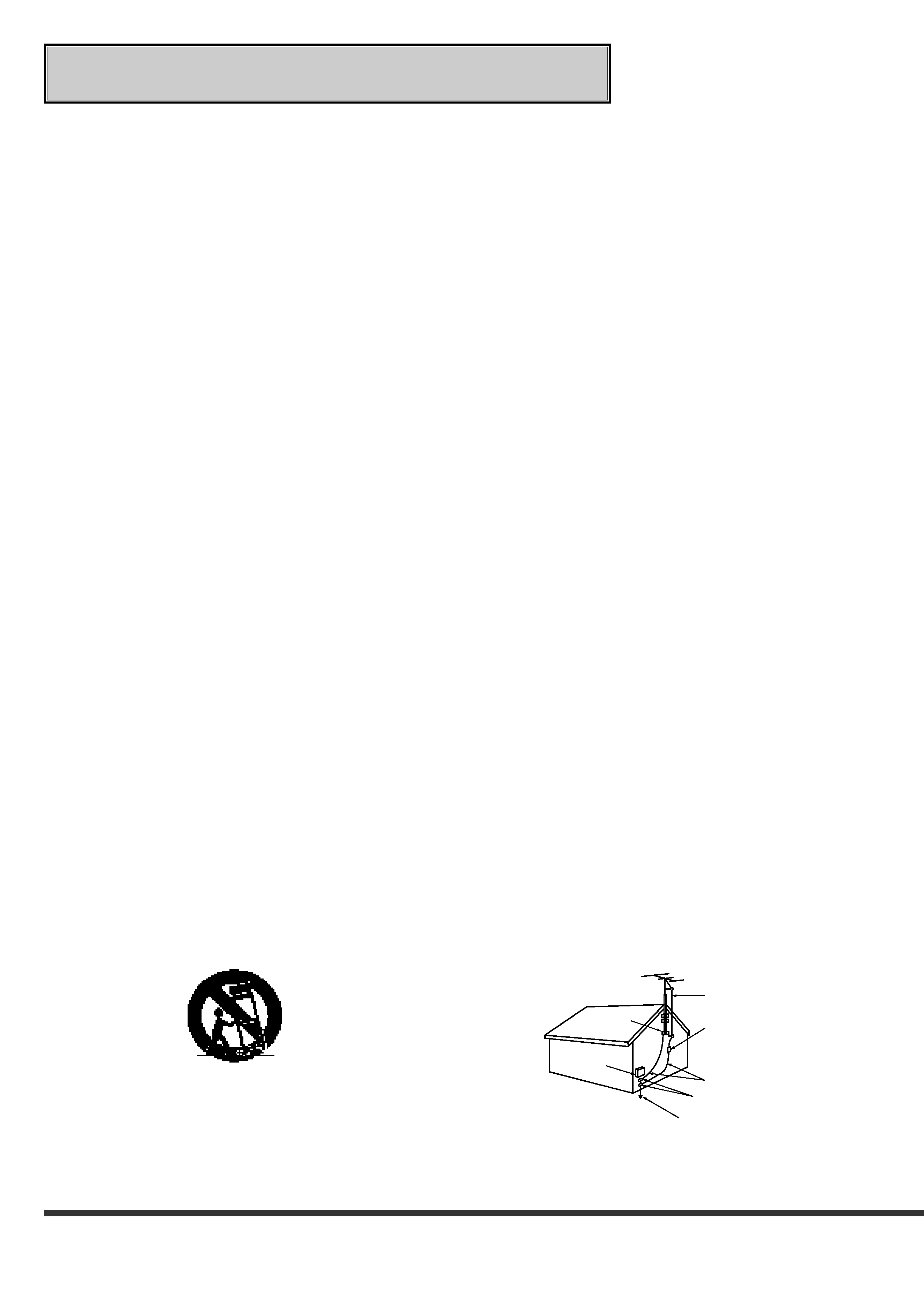
ANTENNA
LEAD IN WIRE
ANTENNA
DISCHARGE UNIT
(NEC SECTION 810-20)
GROUNDING
CONDUCTORS
(NEC SECTION 810-21)
GROUND CLAMPS
POWER SERVICE GROUNDING
ELECTRODE SYSTEM
(NEC ART 250, PART H)
GROUND CLAMP
ELECTRIC
SERVICE
EQUIPMENT
NEC NATIONAL ELECTRICAL CODE
EXAMPLE OF ANTENNA GROUNDING
IMPORTANT SAFEGUARDS
1
Read Instructions
All the safety and operating instructions should be read
before the product is operated.
2
Retain Instructions
The safety and operating instructions should be retained
for future reference.
3
Heed Warnings
All warnings on the product and in the operating in-
structions should be adhered to.
4
Follow Instructions
All operating and use instructions should be followed.
5
Cleaning
Unplug this product from the wall outlet before clean-
ing. Do not use liquid cleaners or aerosol cleaners.
Use a damp cloth for cleaning.
6
Attachments
Do not use attachments not recommended by the prod-
uct manufacturer as they may cause hazards.
7
Water and Moisture
Do not use this product near water -- for example, near
a bath tub, wash bowl, kitchen sink, laundry tub, in a
wet basement, or near a swimming pool, and the like.
8
Accessories
Do not place this product on an unstable cart, stand,
tripod, bracket, or table. The product may fall, causing
serious injury to a child or adult, and serious damage
to the product. Use only with a cart, stand, tripod,
bracket, or table recommended by the manufacturer,
or sold with the product. Any mounting of the product
should follow the manufacturer's instructions, and
should use a mounting accessory recommended by the
manufacturer.
9
A product and cart combination should be moved with
care. Quick stops, excessive force, and uneven sur-
faces may cause the product and cart combination to
overturn.
10 Ventilation
Slots and openings in the cabinet are provided for ven-
tilation and to ensure reliable operation of the product
and to protect it from overheating, and these openings
must not be blocked or covered. The openings should
never be blocked by placing the product on a bed, sofa,
rug, or other similar surface. This product should not
be placed in a built-in installation such as a bookcase
or rack unless proper ventilation is provided or the
manufacturer's instructions have been adhered to.
11 Power Sources
This product should be operated only from the type of
power source indicated on the marking label. If you
are not sure of the type of power supply to your home,
consult your product dealer or local power company.
For products intended to operate from battery power,
or other sources, refer to the operating instructions.
12 Grounding or Polarization
This product is equipped with a polarized alternating-
current line plug (a plug having one blade wider than
the other). This plug will fit into the power outlet only
one way. This is a safety feature. If you are unable to
insert the plug fully into the outlet, try reversing the plug.
If the plug should still fail to fit, contact your electrician
to replace your obsolete outlet. Do not defeat the safety
purpose of the polarized plug.
13 Power-Cord Protection
Power-supply cords should be routed so that they are
not likely to be walked on or pinched by items placed
upon or against them, paying particular attention to
cords at plugs, convenience receptacles, and the point
where they exit from the product.
14 Outdoor Antenna Grounding
If an outside antenna or cable system is connected to
the product, be sure the antenna or cable system is
grounded so as to provide some protection against volt-
age surges and built-up static charges.
Article 810 of the National Electrical Code, ANSI/
NFPA 70, provides information with regard to proper
grounding of the mast and supporting structure, ground-
ing of the lead-in wire to an antenna discharge unit,
size of grounding conductors, location of antenna-dis-
charge unit, connection to grounding electrodes, and
requirements for the grounding electrode.

5
15 Lightning
For added protection for this product during a lightning
storm, or when it is left unattended and unused for long
periods of time, unplug it from the wall outlet and dis-
connect the antenna or cable system. This will prevent
damage to the product due to lightning and power-line
surges.
16 Power Lines
An outside antenna system should not be located in
the vicinity of overhead power lines or other electric
light or power circuits, or where it can fall into such
power lines or circuits. When installing an outside an-
tenna system, extreme care should be taken to keep
from touching such power lines or circuits as contact
with them might be fatal.
17 Overloading
Do not overload wall outlets, extension cords, or inte-
gral convenience receptacles as this can result in fire
risk or electric shock.
18 Object and Liquid Entry
Never push objects of any kind into this product through
openings as they may touch dangerous voltage points
or short-out parts that could result in a fire or electric
shock. Never spill liquid of any kind on the product.
19 Servicing
Do not attempt to service this product yourself as open-
ing or removing covers may expose you to dangerous
voltage or other hazards. Refer all servicing to quali-
fied service personnel.
20 Damage Requiring Service
Unplug this product from the wall outlet and refer ser-
vicing to qualified service personnel under the follow-
ing conditions:
(a) When the power-supply cord or plug is damaged.
(b) If liquid has been spilled, or objects have fallen into the
product.
(c) If the product has been exposed to rain or water.
(d) If the product does not operate normally by follow-
ing the operating instructions. Adjust only those
controls that are covered by the operating instruc-
tions as an improper adjustment of other controls
may result in damage and will often require exten-
sive work by a qualified technician to restore the
product to its normal operation.
(e) If the product has been dropped or damaged in
any way.
(f) When the product exhibits a distinct change in per-
formance this indicates a need for service.
21 Replacement Parts
When replacement parts are required, be sure the ser-
vice technician has used replacement parts specified
by the manufacturer or have the same characteristics
as the original part. Unauthorized substitutions may
result in fire, electric shock or other hazards.
22 Safety Check
Upon completion of any service or repairs to this prod-
uct, ask the service technician to perform safety checks
to determine that the product is in proper operating
condition.
23 Heat
The product should be situated away from heat sources
such as radiators, heat registers, stoves, or other prod-
ucts (including amplifiers) that produce heat.
Declaration of Conformity
Model Number
: VU-LD20U
Trade Name
: JVC
Responsible Party
: JVC Americas Corp.
Address
: 1700 Valley Road Wayne.
N.J. 07470
Telephone Number
: 973-315-5000
This device complies with Part 15 of FCC Rules.
Operation is subject to the following two conditions:
(1) This device may not cause harmful interference, and (2) this device must accept any interference received,
including interference that may cause undesired operation.
Changes or modifications not expressly approved by the party responsible for compliance could void the user's
authority to operate the equipment.
COMPLIANCE NOTICE OF INDUSTRY CANADA
This Class B digital apparatus complies with Canadian ICES-003.
NOTICE DE CONFORMITE AU CANADA
Cet appareil numérique de la classe B est comforme à la norme NMB-003 du Canada.