PC-XC350
SERVICE MANUAL
CD PORTABLE COMPONEMT SYSTEM
PC-XC350
contents
Safety precaution ------------------ 1-2
Block/Wiring Diagram ----------------- 1-16
Disassembly method -------------- 1-4
Circuit Diagram ------------------------- 1-18
Adjustment method ---------------- 1-6
PCB drawing ---------------------------- 1-20
TOC read ---------------------------- 1-11
Assembly -------------------------------- 1-22
Major IC Description ---------------1-12
Packing ----------------------------------- 1-32
No. xxxxx
COPYRIGHT © 2001 VICTOR COMPANY OF JAPAN,LTD (By JCA)
OCT 2001
Area Suffix
J-----USA
C-----CANADA
Unit No.
SP-PCXC350
Unit No.
SP-PCXC350
Unit No.
SP-PCXC350
PC-XC350
1. This design of this product contains special hardware and many circuits and components specially for
safety purposes. For continued protection, no changes should be made ti the original design unless
authorised in writing by the manufacturer. Replacement parts must be identical to those used in the
original circuits. Services should be performed by qualified personel only.
2. Alterations of the design or circuitry of the product should not be made. Any design alterations of the
product should not be made. Any design alterations or additions will void the manufacturer's warranty
and will further relieve the manufacturer of responsibility for personal injury or property damage
resulting therefrom.
3. Many eletrical and mechanical parts in the products have special safety-related characteristics.
These characteristics are often not evident from visual inspection nor can the protection afforded by
them necessarily be obtain by using replaement components rated for higher voltage, the Parts
List of Service manual. Electrical components having such features ate identified by the shading on the
schematics and by (
) on the parts List in the Service Manual. The use of a substitute
repalcement which does not have the same safety characteristics as the recommended replacement
parts shown in the Parts List of Service manual may create shock, fire, or other hazards.
4. The leads in the products are routed and dressed with ties, clamps, tubing's, barriers and the like to
be separated from live parts, high temperatures parts, moving parts and/or sharp edges for the
prevention of electric shcok and fire hazard. When service is required, the original leat routing and
dress should be observed, and it should be confirmed that they have been returned to normal, after
re-assembling.
5. Leakage current check (Electrical Shock hazard testing)
After re-assembling the product, always perform an isolation check on the exposed metap Parts of the
product (antenna terminals, knobs, metal cabinet, screw heads, headphone jack, control shafts, etc.)
to be sure the product is safe to operate without danger of electrical shock.
Do not use a line isloation transformer during this check.
Plug the AC line cord directly into the AC outlet. Using a "Leakage Current Tester", measure the
leakage current from each ecposed metal parts of the cabinet, particularly and exposed metal
part having a return path to the chassis, to a known good earth ground. Any leakage current must
not exceed 0.5mA AC (r.m.s.)
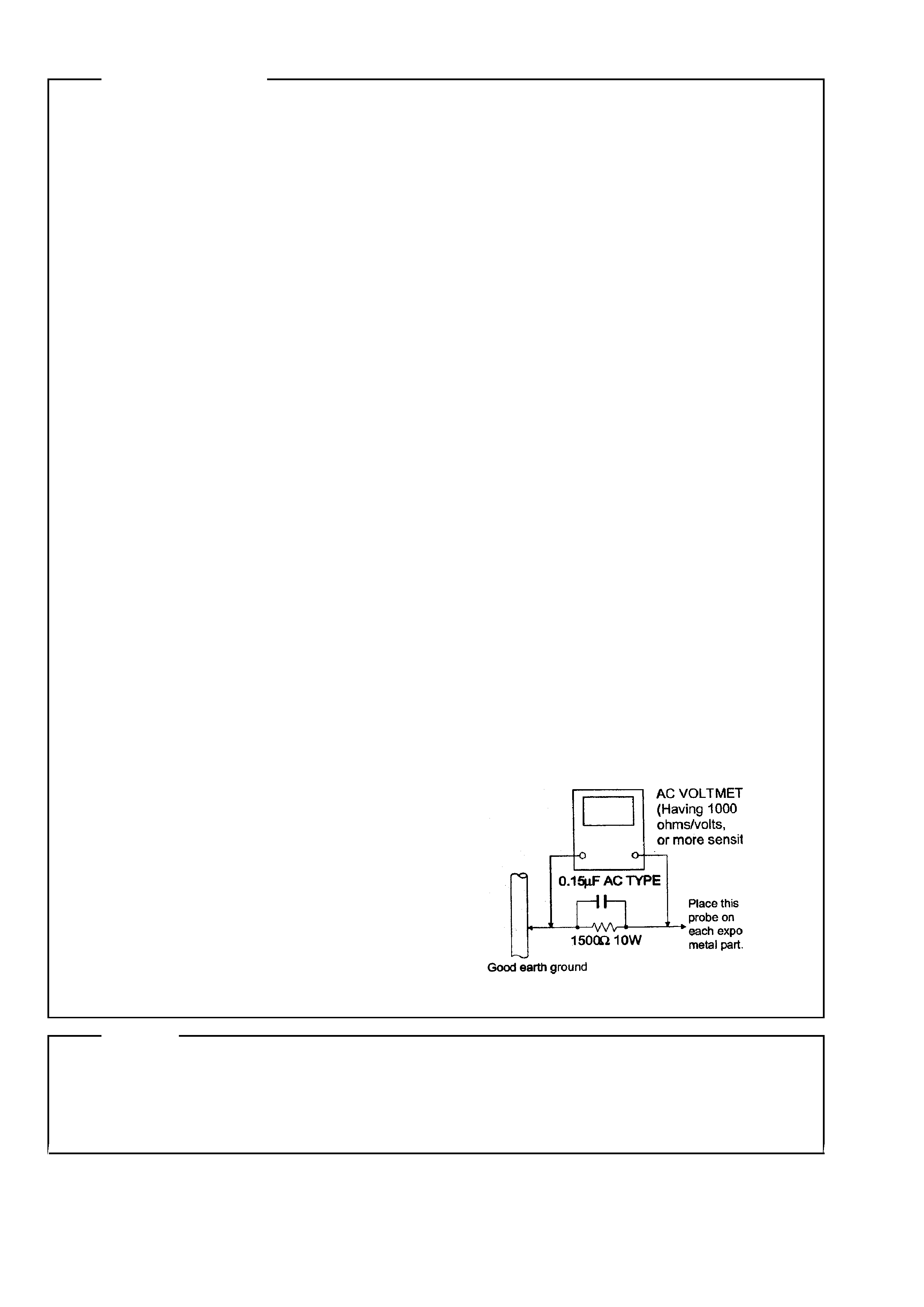
Alternate check method
Plug the AC line cord directly into the AC outlet. Use an AC voltmeter having, 1,000 ohms per
volt or more sensitvity in the following manner. Connect a 1,500 ohm 10W resistor paralleled by a
0.15uF AC-type capacitor between an exposed
metal part and a known good earth ground.
Measure the AC voltage across the resistor with
the AC voltmeter.
Move the resistor connection to each exposed
metal part, particularly and exposed metal part
having a return path to te chassis and
measure the AC voltage across the resistor. Now,
reverse the plug in the AC outlet and repeat
each measurement. Voltage measured Any must
not exceed 0.75 V AC (r.m.s.). This corresponds
to 0.5 mA AC (r.m.s.).
1. This equipment has been designed and manufactured to meet international safety standards.
2. It is the legal responsibility of the repairer to ensure that these safety standards are maintained.
3. repairs must be made in accordance with the relevant safety standards.
4. It is essential that safety critical components are replaced by approved parts.
5. It mains voltage selector is provided, check setting for local voltage.
CAUTION
Burrs formed during moulding may be left over on some parts of the chassis. Therefore,
pay attention to such burrs in the case of performing repair of this system.
Safety Precautions
Warning
1 - 2
PC-XC350
Preventing static electricity
Electrostatic discharge (ESD), which occurs when static electricity stored in the body, fabric, etc. is discharged,
can destroy the laser diode in the traverse unit (optical pcikup). Take care to prevent this when performing repairs.
1.1. Grounding to prevent damage by static electricity
Static electricity in the work area can destroy the optical pickup (laser diode) in devicessuch as DVD players.
Be careful to use proper grounding in the area where repairs are being performed.
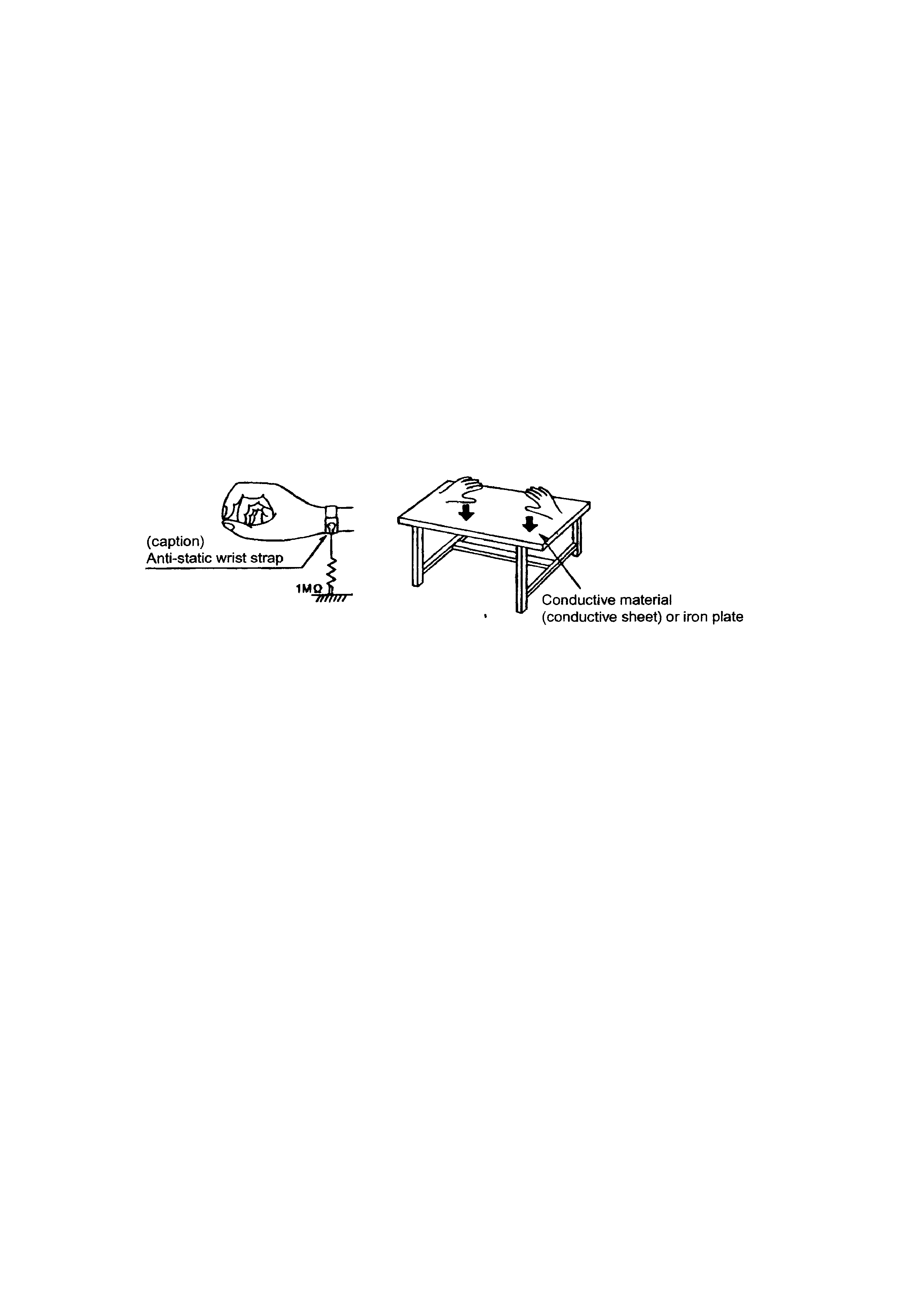
1.1.1. Gound the workbench
1. Ground the workbench by laying conductive material (such as a conductive sheet) or an iron plate over
it before placing the traverse unit (optical pickup) on it.
1.1.2. Ground yourself
1. Use an anti-static wrist starp to release and static electricity built up in your body.
1.1.3. Handling the optical pcikup
1. In order to maintain quality during transport and before installation, both sides of the laser diode on the
replacement optical pickup are storted. After replacement, return the shorted parts to their original condition.
(Refer to the text.)
2. Do not use a tester to check the condition of the laserdiode in the optical pickup. The tester's internal power
source can easily destory the laser diode.
1.2. Handling the traverse unit (optical pickup)
1. Do not subject the traverse unit (optical pcikup) to strong shocks, as it is a sensitive, complex unit.
2. Cut off the shorted part of the flexible cable using nippers, etc. after replacing the optical pickup. For specific
details, refer to the replacement procdeure in the text. Remove the anti-static pin when replacing the traverse
unit. Be careful not to take too long a time when attaching itto the connector.
3. Handle the flexible cable carefully as it may break when subjected to strong force.
4. It is not possible to adjust the semi-fixed resistor that adjusts the laser power. Do not return it.
1 - 3
PC-XC350
Disaeesmbly method
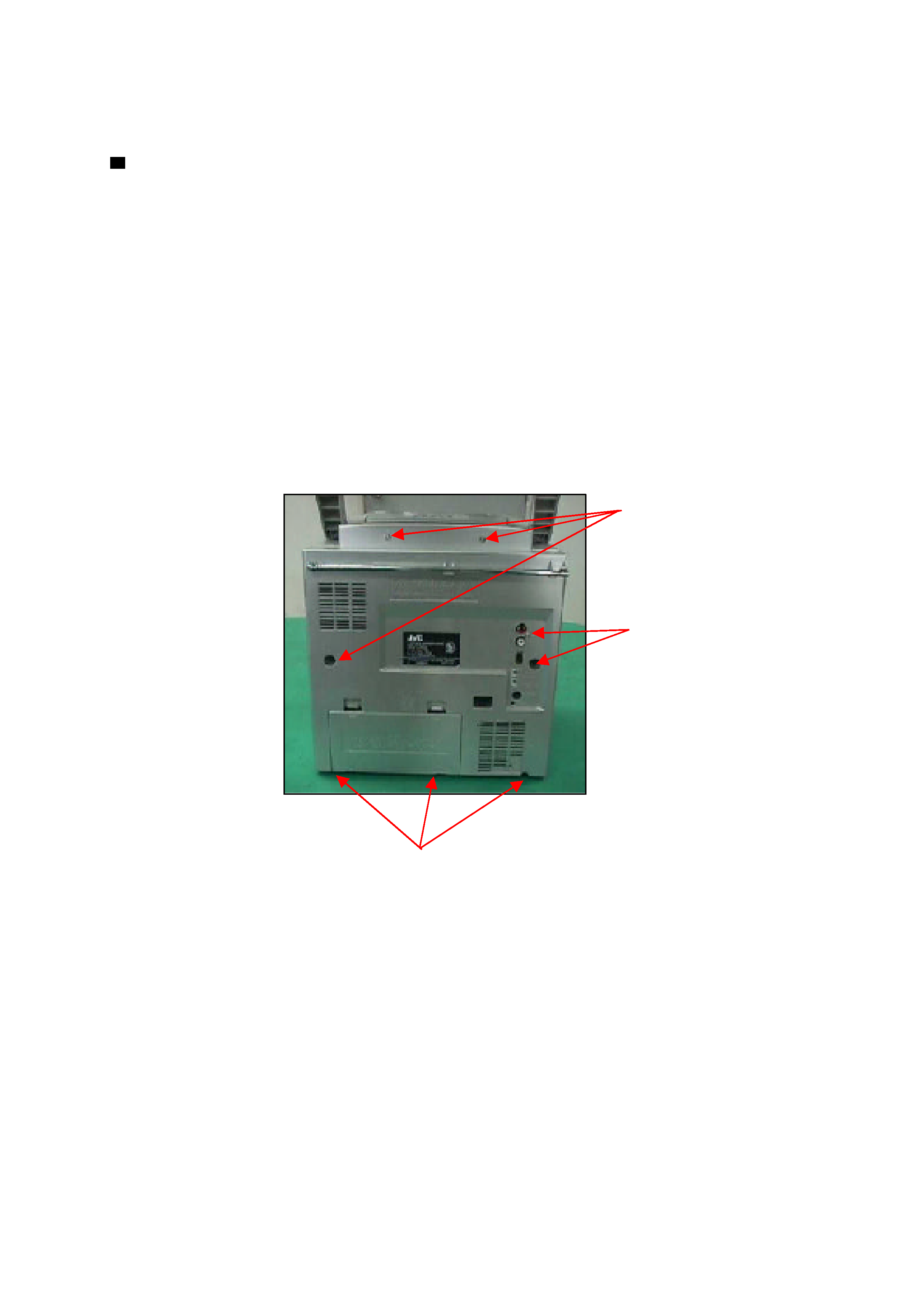
Removing the rear panel
1. From behind the body, remove the eight screws A
retaining the rear panel.
2. Then remove the two screws B retaining the rear panel.
3. Take out the rear panel from the body.
Note:
Be careful of the FM antenna white wire, it is connection with the tuner PCB up side.
You can directly take out from the tuner PCB.
When you re-assembly the product, plug the FM antenna white wire into the Tuner PCB's
"FM ANT" position.
1 - 4
Screw A.
Screw A.
Screw B.
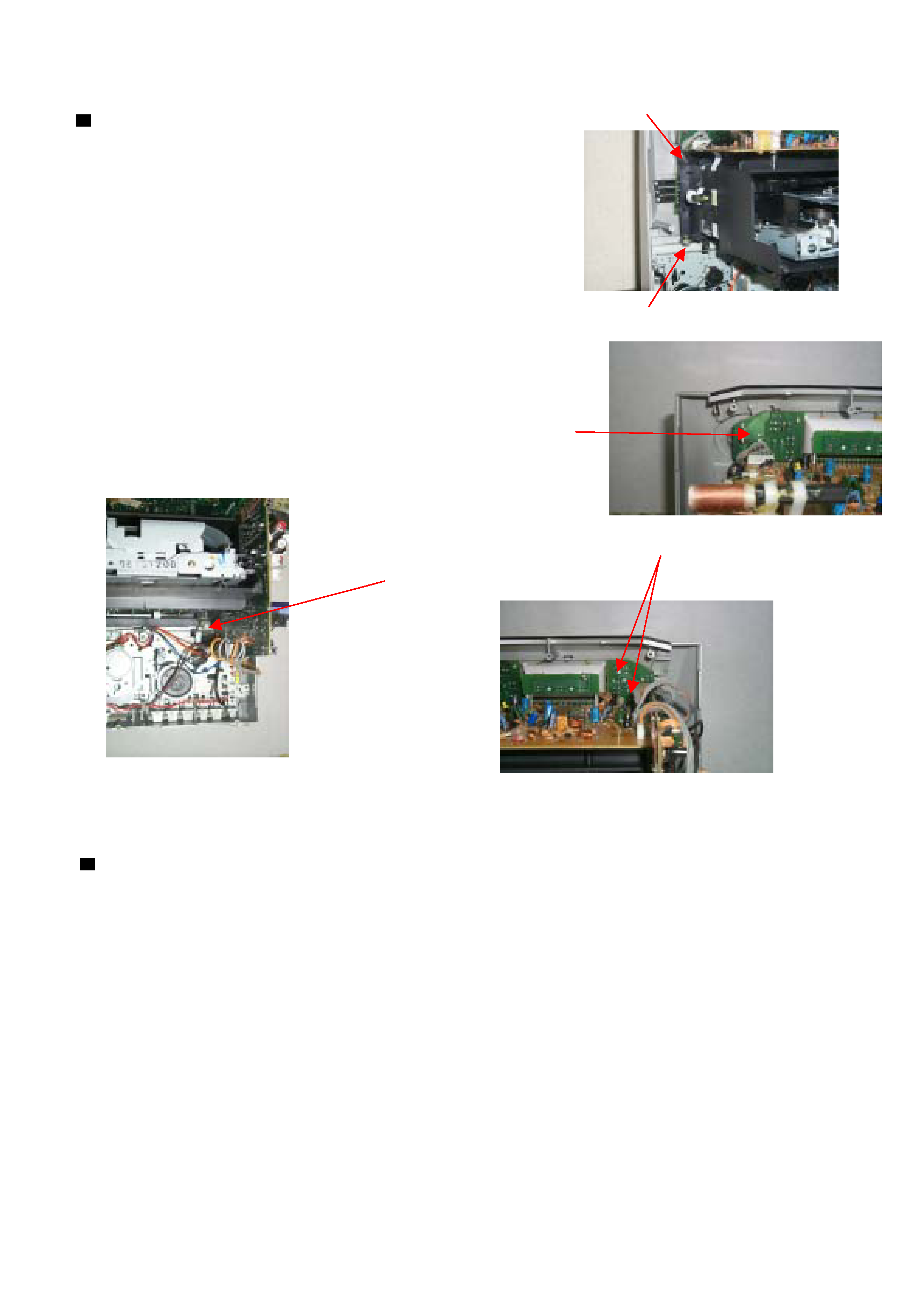
PC-XC350
Removing the CD mechanism
E
1. Remove the rear panel
2. Removing the two screws E retaing the 3CD
mechanism cover.
3. Removing the crew F retaing the control PCB
left side.
E
4. Remove the srews G retaing on the 3CD mechanism cover
& the two screws H retaining on the control PCB
F
G
H
Removing the Main PCB
1. Remove rear panel
2. Remove the 3CD mechanism
3. Remove the four screws attaching the
main PCB.
1 - 5