SERVICE MANUAL
No.49662
Dec. 2001
COPYRIGHT
2001 VICTOR COMPANY OF JAPAN, LTD.
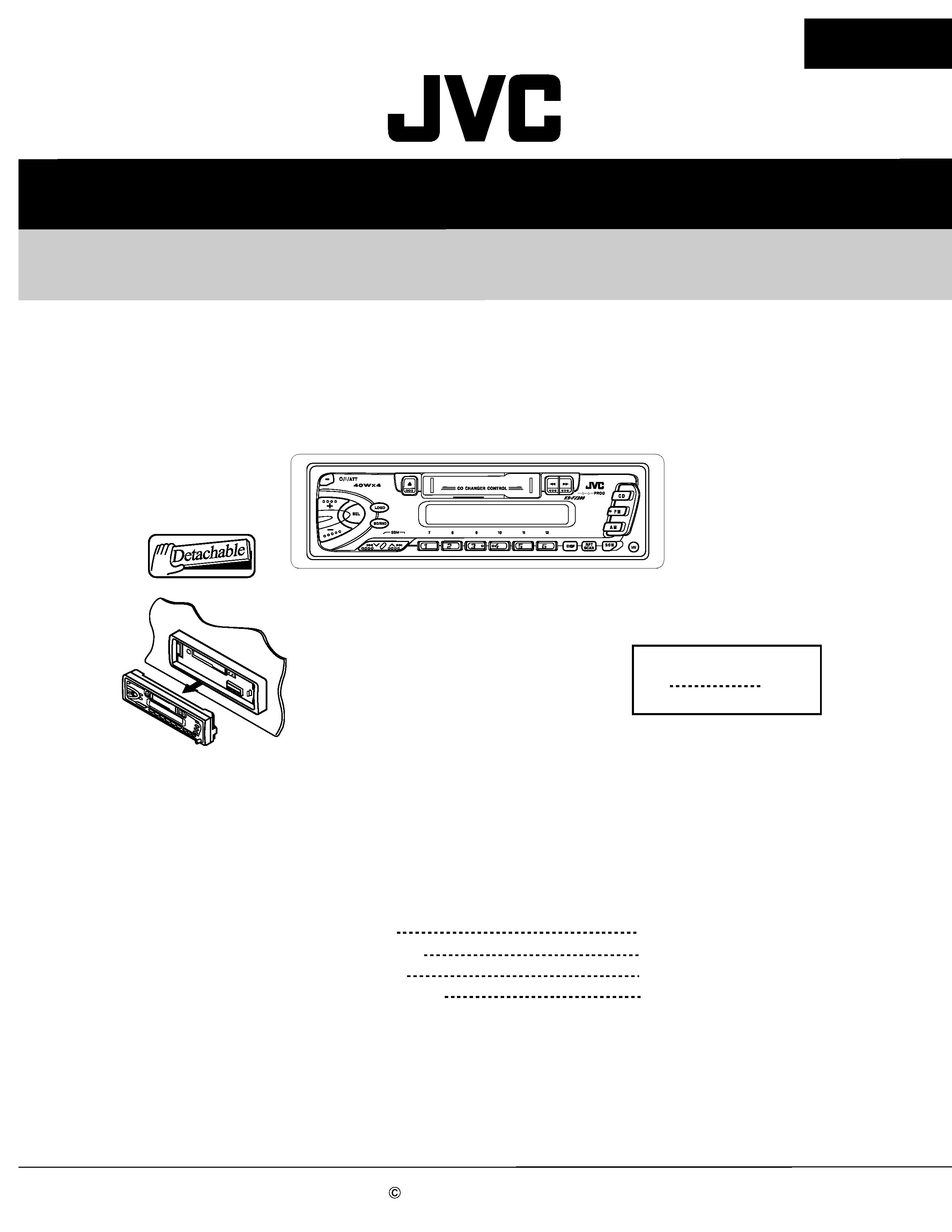
KS-FX288
KS-FX288
Area Suffix
UF
China
CASSETTE RECEIVER
Contents
Safety precaution
Disassembly method
Adjustment method
Description of major ICs
1- 2
1- 3
1- 12
1- 16

1-2
KS-FX288
!
Burrs formed during molding may be left over on some parts of the chassis. Therefore,
pay attention to such burrs in the case of preforming repair of this system.
Safety precaution
1-3
KS-FX288
Fig. 3
Disassembly method
Detaching the front panel unit
( See Fig.1 )
Push the Release button in the direction of arrow to
detach the front panel unit.
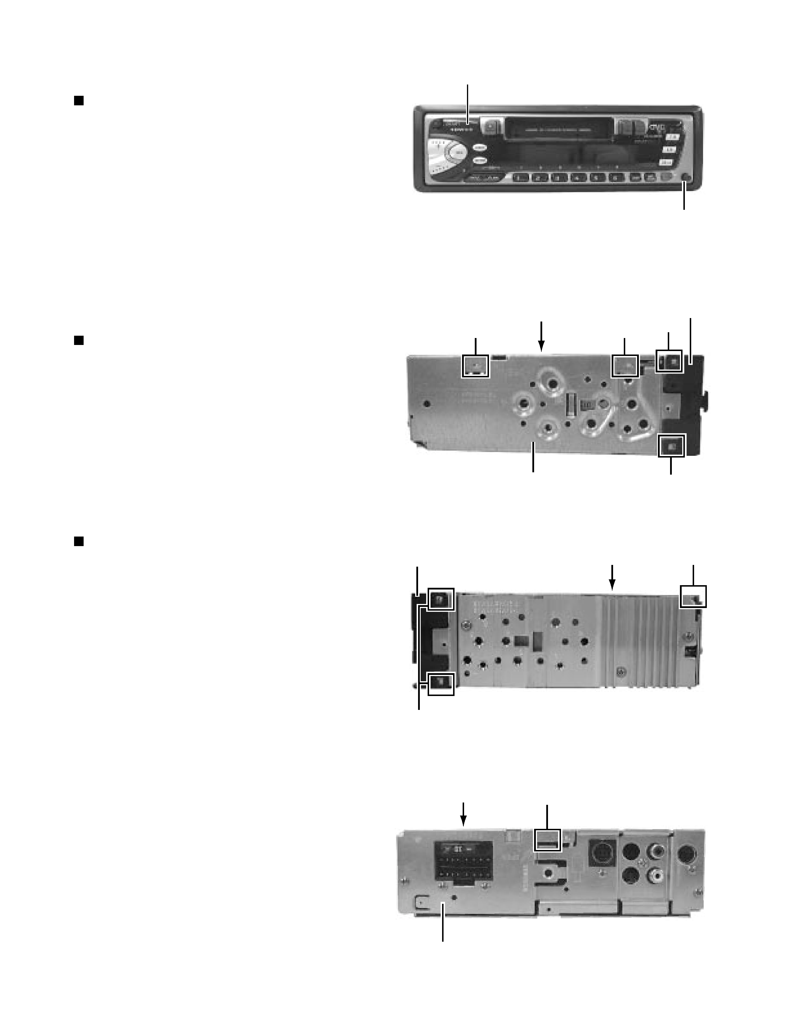
Removing the front chassis
( See Fig. 2 and 3 )
Disengage the four tabs ( a ) in the right and left sides of
unit and pull the front chassis forward to remove it.
Removing the bottom cover
( See Fig. 2 to 4 )
1. Removing the front chassis.
2. Turn the unit up side down.
3. Insert the four engagements ( b, c, d, e ) to the
screwdriver .
4. Turn the screwdriver and remove the bottom
cover.
Fig. 2
Fig. 4
Fig. 1
Front chassis
Bottom cover
Top chassis
Bottom cover
a
a
b
c
a
Front chassis
d
Bottom cover
Rear panel
e
Front panel unit
Push the release button
1-4
KS-FX288
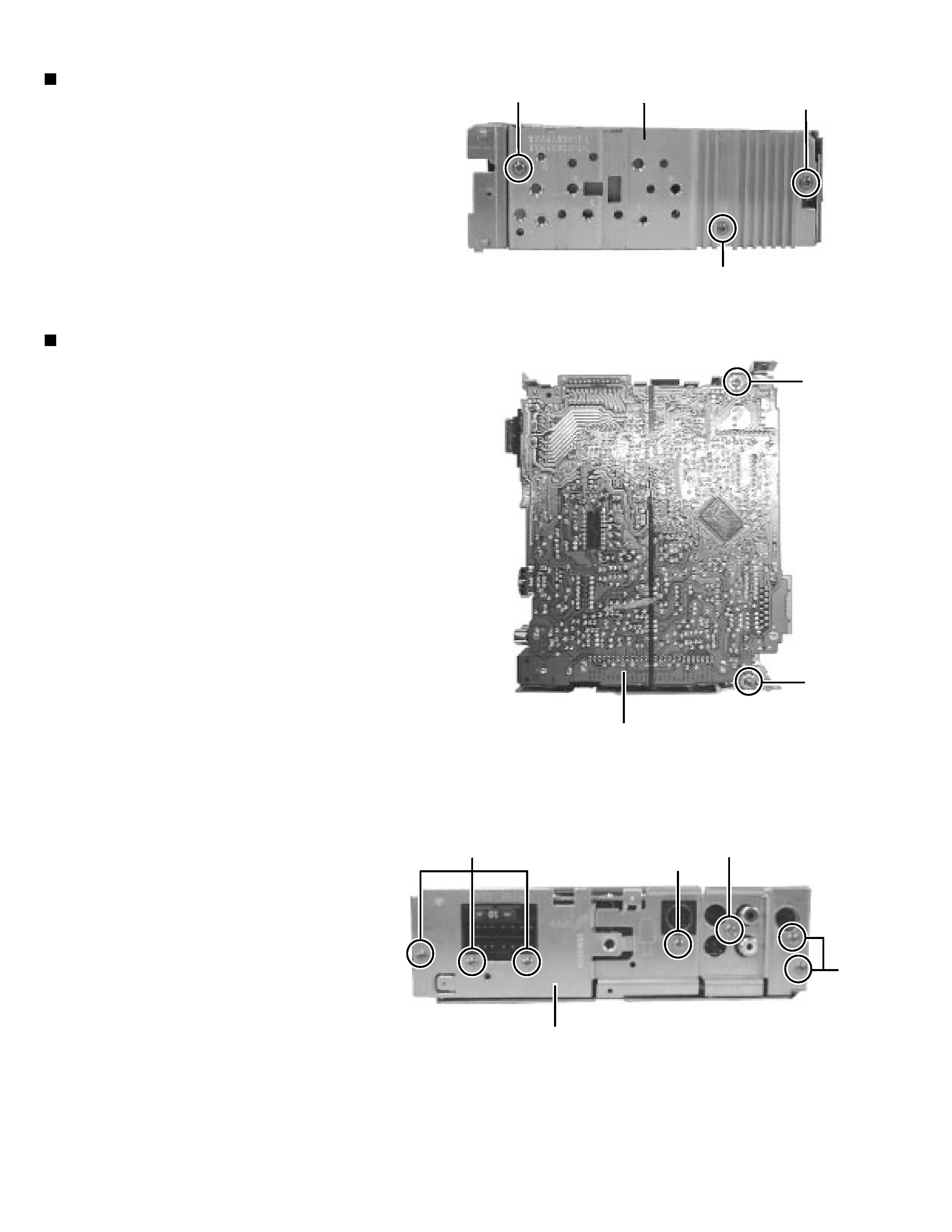
Removing the heat sink (See Fig.5)
1. Removing the front chassis.
2. Removing the bottom cover
3. Remove the three screws ( 1 and 1' ) retaining the
heat sink.
Removing the main board assembly
( See Fig. 5 to 7)
1. Removing the front chassis.
2. Removing the bottom cover.
3. Removing the heat sink.
Attach the heat sink with a screw ( 1' ) on operat-
ing checks.
4. Remove the two screws ( 2 ) retaining the main
board assembly.
5. Remove the six screws ( 3 ) and one screw ( 3' ) retaining
6. Separate the main board assembly and cassette
mechanism assembly.
7. Take out the main board assembly.
Fig. 5
Fig. 6
Fig. 7
(
)
the rear panel.
Heat sink
1
1
1'
2
2
Main board assembly
Rear panel
3
3
3'
3
1-5
KS-FX288
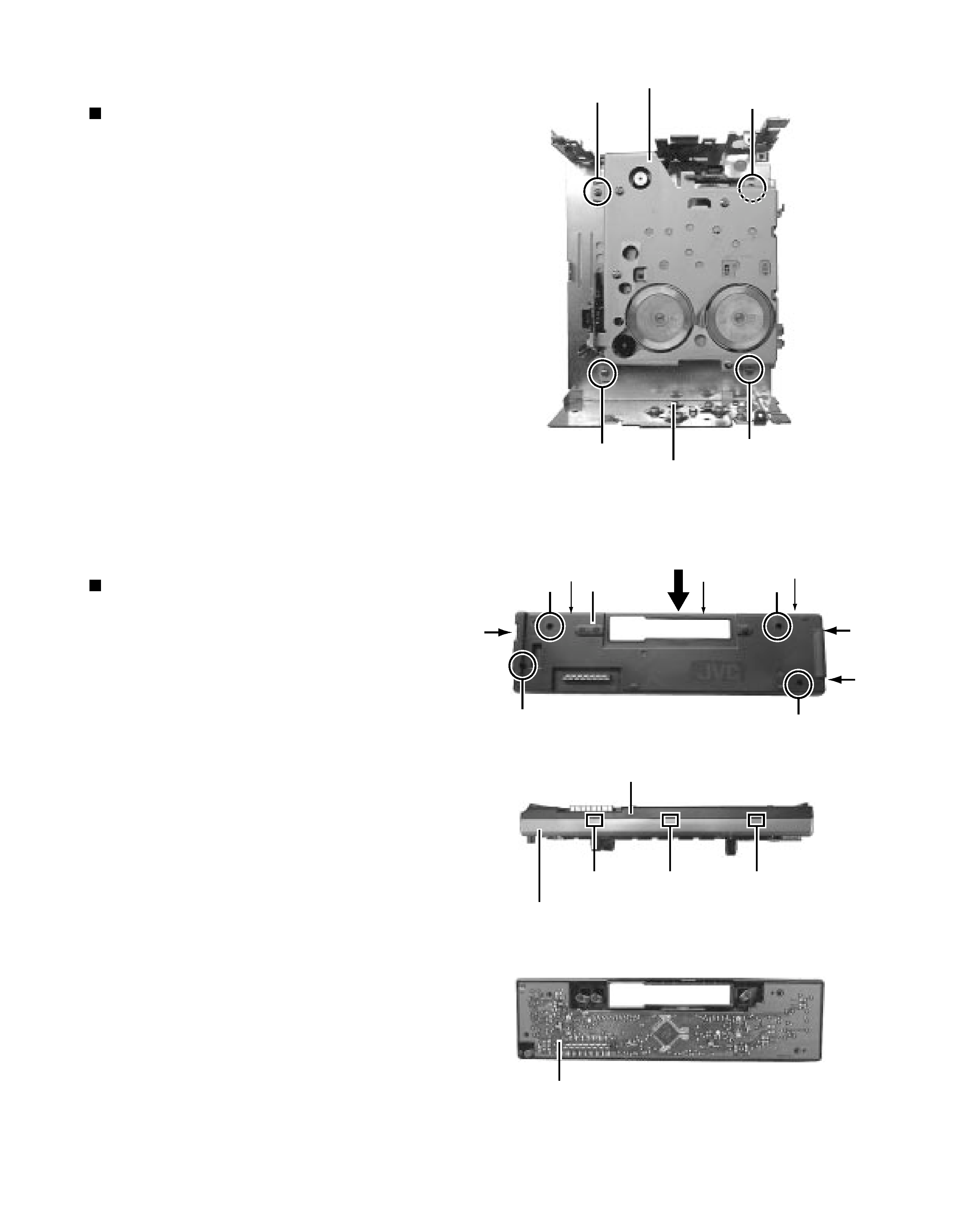
Fig. 9
Fig. 11
Fig. 10
Removing the cassette mechanism assembly
( See Fig. 8 )
1. Removing the front chassis.
2. Removing the bottom cover.
3. Removing the heat sink.
4. Removing the main board assembly.
5. Remove the four screws ( 4 ) retaining the cassette
mechanism.
6. Separate the top chassis and cassette mechanism.
Fig. 8
Removing the operation switch board
( See Fig. 9 to 11)
1. Detaching the front panel unit.
2. Turn the front panel back side down.
3. Remove the four screws ( 5 ) retaining the front
cover
4. Open the front cover gradually by disengaging the
three engagements ( g ) while pushing the top of
the front cover in the arrow "A" direction, then
disengage the three engagements ( h ) on the both
sides.
5. Place the front panel unit front side down.
6. Disengage the three engagements ( i ) on the
bottom to separate the front cover from the front
panel.
(Be careful not to lose the button springs.)
Front side
Cassette mechanism
Top chassis
4
4
4
4
g
g
g
Front cover
A
5
5
5
5
h
h
h
Front cover
Front panel
i
i
i
Operation switch board