SERVICE MANUAL
No. 82894
August 2001
HM-DH30000U
SPECIFICATIONS
D-VHS DIGITAL RECORDER
Printed in Japan
This service manual is printed on 100% recycled paper.
COPYRIGHT © 2001 VICTOR COMPANY OF JAPAN, LTD.
HM-DH30000U
No.
82894
JVC SERVICE & ENGINEERING COMPANY OF AMERICA
DIVISION OF JVC AMERICAS CORP.
Head office
East Coast
Midwest
West Coast
Atlanta
Hawaii
:
:
:
:
:
:
1700 Valley Road Wayne, New Jersey 07470-9976
10 New Maple Avenue Pine Brook, New Jersey 07058-9641
705 Enterprise Street Aurora, Illinois 60504-8149
5665 Corporate Avenue Cypress, California 90630-0024
1500 Lakes Parkway Lawrenceville, Georgia 30043-5857
2969 Mapunapuna Place Honolulu, Hawaii 96819-2040
(973)315-5000
(973)396-1000
(630)851-7855
(714)229-8011
(770)339-2582
(808)833-5828
JVC CANADA INC.
Head office
Montreal
Vancouver
:
:
:
21 Finchdene Square Scarborough, Ontario M1X 1A7
16800 Rte Trans-Canadienne, Kirkland, Quebec H9H 5G7
13040 Worster Court Richmond, B.C. V6V 2B3
(416)293-1311
(514)871-1311
(604)270-1311
S40895-03
MTP
NTSC
REC LINK
POWER
TIMER
STOP/EJECT
PL
AY
PULL-OPEN
CANCEL
TIMER
START
STOP
DATE
PLAY
REW
<
BACK
REC
STOP
PAUSE
FF
>
CH
POWER
TV/VCR
C. RESET
DBS
. , ?
ABC
DEF
GHI
JKL
MNO
PQRS
TUV
WXYZ
DAILY(M-F)
AUX
WEEKLY
PROG.
CHECK
PROG.
HS/STD/LS3
SP/EP
SKIP SEARCH
A/B
DISPLAY
ENTER/OSD
A.MONITOR
VCR TV CABLE/DBS
123
45
6
7
89
0
2
4
1
3
EXPRESS PROGRAMMING
JOG/
SHUTTLE
M ENU
OK
NAVIGAT
ION
TV CH +
TV CH
TV
VOL
+
TV
VOL
GENERAL
Power requirement
: AC 120 V`, 60 Hz
Power consumption
Power on
: 55 W
Power off
: 18 W
Temperature
Operating
: 5°C to 40°C (41°F to 104°F)
Storage
: 20°C to 60°C (4°F to140°F)
Operating position
: Horizontal only
Dimensions (W x H x D)
: 435 mm x 105 mm x 383 mm
(17-3/16" x 4-3/16" x 15-1/8")
Weight
: 5.7 kg (12.6 lbs)
Maximum recording time
D-VHS (HS)
: 210 min. with DF-420 video cassette
D-VHS (STD)
: 420 min. with DF-420 video cassette
D-VHS (LS3)
: 1260 min. with DF-420 video cassette
S-VHS/VHS (SP)
: 210 min. with ST-210 video cassette
S-VHS/VHS (EP)
: 630 min. with ST-210 video cassette
VIDEO/AUDIO (D-VHS)
Video format
: MPEG2 standard
Audio format
: Encode
MPEG1 Layer2
Decode MPEG1 Layer2
Dolby Digital
Track composition
Tape speed
: 33.4 mm/sec (HS mode)
16.67 mm/sec (STD mode)
5.55 mm/sec (LS3 mode)
Head azimuth
: ±30 deg
Drum rotation
: 1800 rpm
Tracking system
: CTL track system
Recording specification
Main data input rate
: 28.2 Mbps (HS mode)
14.1 Mbps (STD mode)
4.7 Mbps (LS3 mode)
Interface
: IEEE1394 compliant
DTCP digital copy protection compatible
VIDEO/AUDIO (S-VHS/VHS)
Format
: S-VHS/VHS NTSC standard
Signal system
: NTSC-type color signal and EIA monochrome
signal, 525 lines/60 fields
Recording/
Playback system
: DA-4 (Double Azimuth) head helical scan system
Signal-to-noise ratio
: 45 dB
Frequency range
Normal audio
: 70 Hz to 10,000 Hz
Hi-Fi audio
: 20 Hz to 20,000 Hz
TUNER
Tuning system
: Frequency-synthesized tuner
Channel coverage
VHF
: Channels 213
UHF
: Channels 1469
CATV
: 113 Channels
TIMER
Clock reference
: Quartz
Program capacity
: 1-year programmable timer/24 programs
Memory backup time
: Approx. 60 min.
CONNECTORS
Input/Output
: i.LINK IN/OUT, DV IN x 2 (4-pin, S200)
RCA connectors (IN x 3, OUT x 2)
S-video connectors (IN x 3, OUT x 2)
Component video OUT (Y, PB/CB, PR/CR) x 1
Digital OUT (optical) x 1
ACCESSORIES
Provided accessories
: Infrared remote control unit, "AA" battery x 2,
Audio cable, RF cable (F-type),
S-video cable (4-pin), Controller
Manufactured under license from Dolby Laboratories.
"Dolby", "Pro Logic", and the double-D symbol are trademarks of Dolby
Laboratories. Confidential unpublished works. Copyright 1992-1997
Dolby Laboratories. All rights reserved.
Specifications shown are for SP mode unless specified otherwise.
E. & O.E. Design and specifications subject to change without notice.

Important Safety Precautions
INSTRUCTIONS
1. DISASSEMBLY
1.1 Disassembly flow chart ................................................................ 1-1
1.2 How to read the disassembly and assembly ................................ 1-1
1.3 Disassembly/assembly method .................................................... 1-1
1.4 Service position ............................................................................ 1-5
1.4.1 How to set the "Service position" ........................................... 1-5
1.4.2 Precautions for cassette loading in the "Service position" ..... 1-5
1.4.3 Cassette loading and ejection methods in the "Service position" 1-5
1.5 Mechanism service mode ............................................................ 1-6
1.5.1 How to set the "Mechanism service mode" ............................ 1-6
1.6 Jig RCU mode ............................................................................. 1-6
1.6.1 Setting the Jig RCU mode ..................................................... 1-6
1.6.2 Setting the User RCU mode .................................................. 1-6
1.7 Opening on the chassis ................................................................ 1-6
1.8 Emergency display function ......................................................... 1-7
1.8.1 Displaying the EMG information ............................................. 1-7
1.8.2 Clearing the EMG history ....................................................... 1-7
1.8.3 EMG content description ........................................................ 1-8
1.8.4 EMG detail information <1> ................................................... 1-9
1.8.5 EMG detail information <2> ................................................. 1-10
2. MECHANISM ADJUSTMENT
2.1 Before starting repair and adjustment ......................................... 2-1
2.1.1 Precautions ............................................................................ 2-1
2.1.2 Checking for proper mechanical operations ........................... 2-1
2.1.3 Manually removing the cassette tape ..................................... 2-1
2.1.4 Jigs and tools required for adjustment ................................... 2-2
2.1.5 Maintenance and inspection .................................................. 2-3
2.2 Replacement of major parts ......................................................... 2-6
2.2.1 Before starting disassembling (Phase matching between
mechanical parts) ................................................................... 2-6
2.2.2 How to set the "Mechanism assembling mode" ..................... 2-6
2.2.3 Cassette holder assembly ...................................................... 2-6
2.2.4 Pinch roller arm assembly ...................................................... 2-8
2.2.5 Guide arm assembly and press lever assembly ..................... 2-8
2.2.6 A/C head ................................................................................ 2-8
2.2.7 Loading motor ........................................................................ 2-8
2.2.8 Capstan motor ....................................................................... 2-9
2.2.9 Pole base assembly (supply or take-up side) ......................... 2-9
2.2.10 Rotary encoder .................................................................. 2-10
2.2.11 Clutch unit .......................................................................... 2-10
2.2.12 Change lever assembly, direct gear, clutch gear and coupling gear .. 2-10
2.2.13 Link lever ............................................................................ 2-11
2.2.14 Cassette gear, control cam and worm gear ....................... 2-11
2.2.15 Control plate ....................................................................... 2-11
2.2.16 Loading arm gear (supply or take-up side) and
loading arm gear shaft ....................................................... 2-12
2.2.17 Take-up lever, take-up head and control plate guide .......... 2-13
2.2.18 Capstan brake assembly .................................................... 2-13
2.2.19 Sub brake assembly (take-up side) .................................... 2-13
2.2.20 Main brake assembly (take-up side), reel disk (take-up side) and
main brake assembly (supply side) ................................................ 2-13
2.2.21 Tension brake assembly, reel disk (supply side) and
tension arm assembly ........................................................ 2-14
2.2.22 Idler lever, idler arm assembly ........................................... 2-14
2.2.23 Stator assembly .................................................................. 2-14
2.2.24 Rotor assembly .................................................................. 2-14
2.2.25 Upper drum assembly ........................................................ 2-15
2.3 Compatibility adjustment ............................................................ 2-16
2.3.1 FM waveform linearity .......................................................... 2-16
2.3.2 Height and tilt of the A/C head ............................................. 2-17
2.3.3 A/C head phase (X-value) .................................................... 2-17
2.3.4 Standard tracking preset ...................................................... 2-18
2.3.5 Tension pole position ............................................................ 2-18
3. ELECTRICAL ADJUSTMENT
3.1 Precaution ................................................................................... 3-1
3.1.1 Required test equipments ..................................................... 3-1
3.1.2 Required adjustment tools ..................................................... 3-1
3.1.3 Color (colour) bar signal,Color (colour) bar pattern ............... 3-1
3.1.4 Switch settings and standard precautions ............................. 3-1
3.1.5 EVR Adjustment ..................................................................... 3-1
3.2 Servo circuit ................................................................................. 3-2
3.2.1 Switching point ....................................................................... 3-2
3.2.2 D-VHS switching point ........................................................... 3-2
3.2.3 Slow tracking preset ............................................................... 3-2
TABLE OF CONTENTS
Section
Title
Page
Section
Title
Page
3.3 Video circuit .................................................................................. 3-3
3.3.1 D/A level ................................................................................. 3-3
3.3.2 EE Y/PB Y (S-VHS/VHS) level ............................................... 3-3
3.3.3 REC color (colour) level ......................................................... 3-3
3.3.4 Video EQ (Frequency response) ............................................ 3-4
3.3.5 Auto picture initial setting ....................................................... 3-4
3.4 Audio circuit .................................................................................. 3-4
3.4.1 Audio REC FM ....................................................................... 3-4
3.5 Demodulator circuit ...................................................................... 3-5
3.5.1 Input level ............................................................................... 3-5
3.5.2 Stereo VCO ............................................................................ 3-5
3.5.3 Stereo filter ............................................................................. 3-5
3.5.4 Separation - 1 ......................................................................... 3-6
3.5.5 Separation - 2 ......................................................................... 3-6
3.5.6 SAP VCO ............................................................................... 3-6
3.6 Digital circuit ................................................................................. 3-6
3.6.1 D-VHS REC level ................................................................... 3-6
3.6.2 PLL f0 ..................................................................................... 3-7
4. CHARTS AND DIAGRAMS
NOTES OF SCHEMATIC DIAGRAM ................................................. 4-1
CIRCUIT BOARD NOTES .................................................................. 4-2
4.1 BOARD INTERCONNECTIONS .................................................. 4-3
4.2 REGULATOR AND SUB REGULATOR SCHEMATIC DIAGRAMS ...... 4-5
4.3 MAIN (VIDEO/AUDIO) SCHEMATIC DIAGRAM .......................... 4-7
4.4 MAIN (SYSCON) SCHEMATIC DIAGRAM .................................. 4-9
4.5 MAIN (TUNER/DEMOD) SCHEMATIC DIAGRAM ..................... 4-11
4.6 MAIN (AUDIO I/O) SCHEMATIC DIAGRAM .............................. 4-13
4.7 MAIN (SYNCDET) SCHEMATIC DIAGRAM .............................. 4-15
4.8 MAIN (MAIN-TERMINAL) SCHEMATIC DIAGRAM ................... 4-17
4.9 3D DIGITAL/4M SCHEMATIC DIAGRAM ................................... 4-19
4.10 TERMINAL-NTSC SCHEMATIC DIAGRAM ............................. 4-21
4.11 S-SUB SCHEMATIC DIAGRAM ............................................... 4-23
4.12 DISPLAY, REC SAFETY/D.CASS SW AND
JACK SCHEMATIC DIAGRAMS .............................................. 4-25
4.13 D-PRE/REC SCHEMATIC DIAGRAM ...................................... 4-27
4.14 DIGITAL(HOST) SCHEMATIC DIAGRAM ................................ 4-29
4.15 DIGITAL(DMAIN) SCHEMATIC DIAGRAM .............................. 4-31
4.16 DIGITAL(D-VHS IF) SCHEMATIC DIAGRAM .......................... 4-33
4.17 DIGITAL(DVX) SCHEMATIC DIAGRAM ................................... 4-35
4.18 DIGITAL(VIDEO IF) SCHEMATIC DIAGRAM .......................... 4-37
4.19 DIGITAL(HD DEC) SCHEMATIC DIAGRAM ............................ 4-39
4.20 DIGITAL(LAPRAS) SCHEMATIC DIAGRAM ............................ 4-41
4.21 DIGITAL(DSP) SCHEMATIC DIAGRAM .................................. 4-43
4.22 DIGITAL(AUDIO AD/DA) SCHEMATIC DIAGRAM ................... 4-45
4.23 DIGITAL(DECRIPTER) SCHEMATIC DIAGRAM ..................... 4-47
4.24 REGULATOR AND SUB REGULATOR CIRCUIT BOARDS .... 4-49
4.25 3D DIGITAL/4M AND S-SUB CIRCUIT BOARDS .................... 4-51
4.26 TERMINAL CIRCUIT BOARD .................................................. 4-52
4.27 DISPLAY, REC SAFETY AND JACK CIRCUIT BOARDS ........ 4-53
4.28 D-PRE/REC CIRCUIT BOARD ................................................ 4-55
4.29 DIGITAL CIRCUIT BOARD ...................................................... 4-57
4.30 MAIN CIRCUIT BOARD ........................................................... 4-61
4.31 VOLTAGE CHARTS .................................................................. 4-64
4.32 FDP GRID ASSIGNMENT AND ANODE CONNECTION ........ 4-65
4.33 REMOTE CONTROLLER SCHEMATIC DIAGRAM ................. 3-66
4.34 WAVEFORMS .......................................................................... 4-67
4.35 CPU PIN FUNCTION ............................................................... 4-68
4.36 SYSTEM CONTROL BLOCK DIAGRAM ................................. 4-69
4.37 AUDIO BLOCK DIAGRAM ....................................................... 4-71
4.38 VIDEO BLOCK DIAGRAM ....................................................... 4-73
4.39 D-VHS BLOCK DIAGRAM ....................................................... 4-77
5. PARTS LIST
5.1 PACKING AND ACCESSORY ASSEMBLY <M1> ....................... 5-1
5.2 FINAL ASSEMBLY <M2> ............................................................ 5-2
5.3 MECHANISM ASSEMBLY <M4> ................................................ 5-4
5.4 ELECTRICAL PARTS LIST .......................................................... 5-6
SW.REG BOARD ASSEMBLY <01> ................................................ 5-6
SUB REG BOARD ASSEMBLY <02> .............................................. 5-7
MAIN BOARD ASSEMBLY <03> ..................................................... 5-8
3D DIGITAL/4M BOARD ASSEMBLY <05> ................................... 5-14
TERMINAL BOARD ASSEMBLY <06> .......................................... 5-16
A/C HEAD BOARD ASSEMBLY <12> ........................................... 5-16
S-SUB BOARD ASSEMBLY <15> ................................................. 5-16
DISPLAY BOARD ASSEMBLY <28> .............................................. 5-17
REC SAFETY BOARD ASSEMBLY <32> ...................................... 5-18
JACK BOARD ASSEMBLY <36> ................................................... 5-18
D-PRE/REC BOARD ASSEMBLY <43> ......................................... 5-18
DIGITAL BOARD ASSEMBLY <50> ............................................... 5-22
LOADING MOTOR BOARD ASSEMBLY <55> .............................. 5-32
Important Safety Precautions
Prior to shipment from the factory, JVC products are strictly inspected to conform with the recognized product safety and electrical codes of the
countries in which they are to be sold. However, in order to maintain such compliance, it is equally important to implement the following precautions
when a set is being serviced.
Fig.1
1. Locations requiring special caution are denoted by labels and in-
scriptions on the cabinet, chassis and certain parts of the product.
When performing service, be sure to read and comply with these
and other cautionary notices appearing in the operation and serv-
ice manuals.
2. Parts identified by the
! symbol and shaded (
) parts are
critical for safety.
Replace only with specified part numbers.
Note: Parts in this category also include those specified to com-
ply with X-ray emission standards for products using
cathode ray tubes and those specified for compliance
with various regulations regarding spurious radiation
emission.
3. Fuse replacement caution notice.
Caution for continued protection against fire hazard.
Replace only with same type and rated fuse(s) as specified.
4. Use specified internal wiring. Note especially:
1) Wires covered with PVC tubing
2) Double insulated wires
3) High voltage leads
5. Use specified insulating materials for hazardous live parts. Note
especially:
1) Insulation Tape
3) Spacers
5) Barrier
2) PVC tubing
4) Insulation sheets for transistors
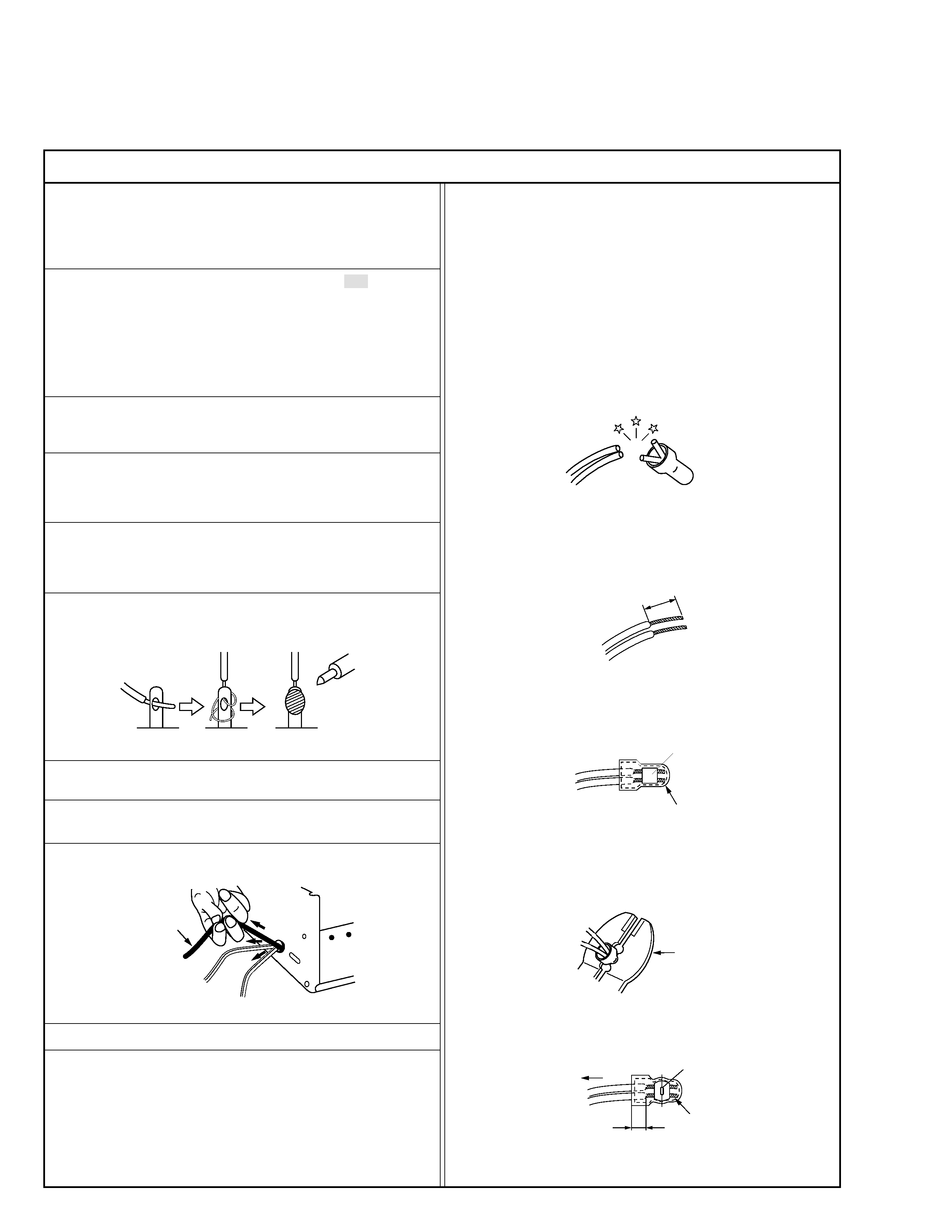
6. When replacing AC primary side components (transformers, power
cords, noise blocking capacitors, etc.) wrap ends of wires securely
about the terminals before soldering.
Power cord
Fig.2
10. Also check areas surrounding repaired locations.
11. Products using cathode ray tubes (CRTs)
In regard to such products, the cathode ray tubes themselves, the
high voltage circuits, and related circuits are specified for compli-
ance with recognized codes pertaining to X-ray emission.
Consequently, when servicing these products, replace the cath-
ode ray tubes and other parts with only the specified parts. Under
no circumstances attempt to modify these circuits.
Unauthorized modification can increase the high voltage value and
cause X-ray emission from the cathode ray tube.
12. Crimp type wire connector
In such cases as when replacing the power transformer in sets
where the connections between the power cord and power trans-
former primary lead wires are performed using crimp type connec-
tors, if replacing the connectors is unavoidable, in order to prevent
safety hazards, perform carefully and precisely according to the
following steps.
1) Connector part number : E03830-001
2) Required tool : Connector crimping tool of the proper type which
will not damage insulated parts.
3) Replacement procedure
(1) Remove the old connector by cutting the wires at a point
close to the connector.
Important : Do not reuse a connector (discard it).
Fig.7
cut close to connector
Fig.3
(2) Strip about 15 mm of the insulation from the ends of the
wires. If the wires are stranded, twist the strands to avoid
frayed conductors.
15 mm
Fig.4
(3) Align the lengths of the wires to be connected. Insert the
wires fully into the connector.
Connector
Metal sleeve
Fig.5
(4) As shown in Fig.6, use the crimping tool to crimp the metal
sleeve at the center position. Be sure to crimp fully to the
complete closure of the tool.
I
·Precautions during Servicing
7. Observe that wires do not contact heat producing parts (heatsinks,
oxide metal film resistors, fusible resistors, etc.)
8. Check that replaced wires do not contact sharp edged or pointed
parts.
9. When a power cord has been replaced, check that 10-15 kg of
force in any direction will not loosen it.
1.2
5
2.0
5.5
Crimping tool
Fig.6
(5) Check the four points noted in Fig.7.
Not easily pulled free
Crimped at approx. center
of metal sleeve
Conductors extended
Wire insulation recessed
more than 4 mm
S40888-01
·Safety Check after Servicing
Examine the area surrounding the repaired location for damage or deterioration. Observe that screws, parts and wires have been returned
to original positions, Afterwards, perform the following tests and confirm the specified values in order to verify compliance with safety
standards.
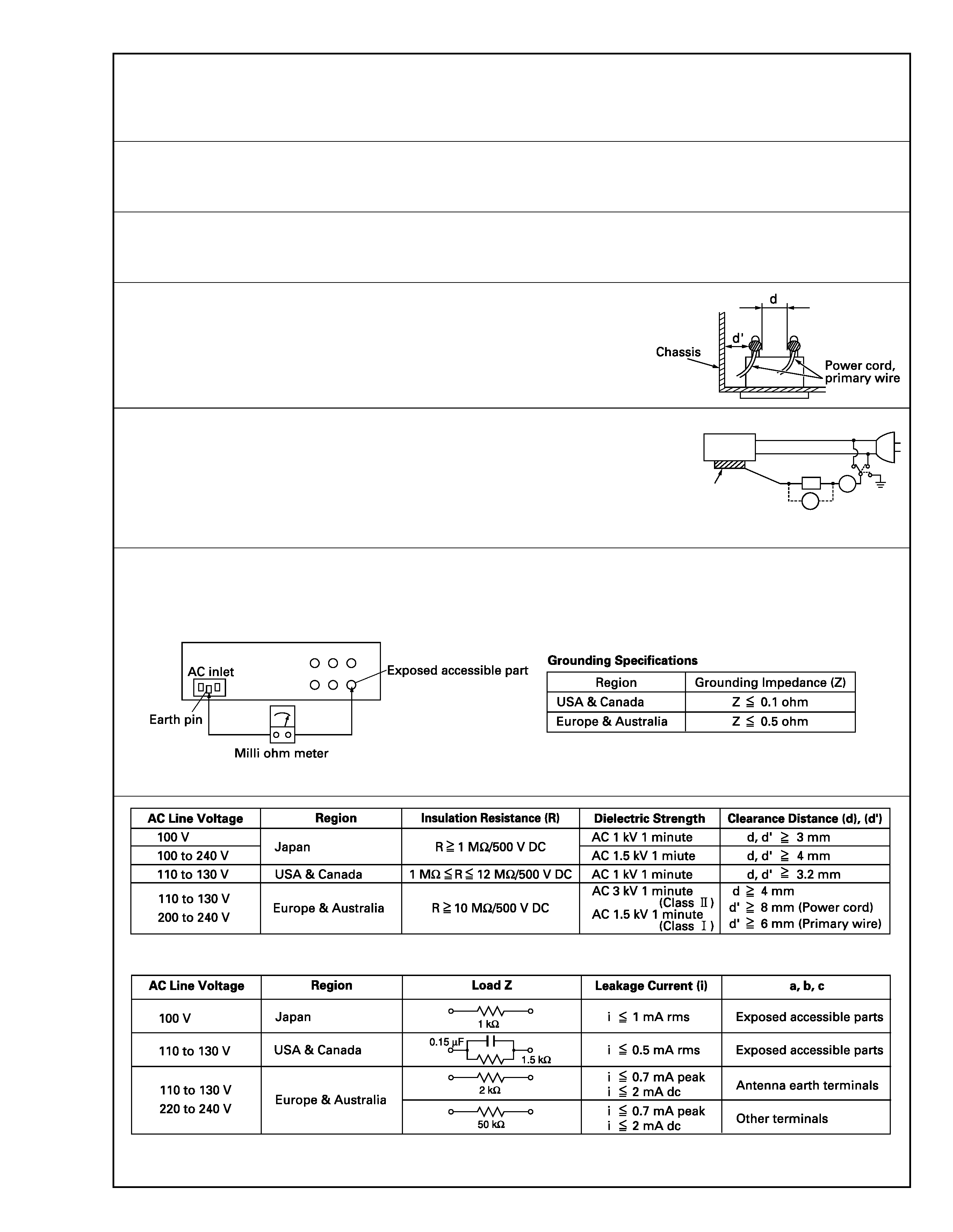
1. Insulation resistance test
Confirm the specified insulation resistance or greater between power cord plug prongs and exter-
nally exposed parts of the set (RF terminals, antenna terminals, video and audio input and output
terminals, microphone jacks, earphone jacks, etc.). See table 1 below.
2. Dielectric strength test
Confirm specified dielectric strength or greater between power cord plug prongs and exposed acces-
sible parts of the set (RF terminals, antenna terminals, video and audio input and output terminals,
microphone jacks, earphone jacks, etc.). See table 1 below.
3. Clearance distance
When replacing primary circuit components, confirm specified clearance distance (d), (d') be-
tween soldered terminals, and between terminals and surrounding metallic parts. See table 1
below.
4. Leakage current test
Confirm specified or lower leakage current between earth ground/power cord plug prongs and
externally exposed accessible parts (RF terminals, antenna terminals, video and audio input and
output terminals, microphone jacks, earphone jacks, etc.).
Measuring Method : (Power ON)
Insert load Z between earth ground/power cord plug prongs and externally exposed accessible
parts. Use an AC voltmeter to measure across both terminals of load Z. See figure 9 and following
table 2.
5. Grounding (Class 1 model only)
Confirm specified or lower grounding impedance between earth pin in AC inlet and externally exposed accessible parts (Video in, Video out,
Audio in, Audio out or Fixing screw etc.).
Measuring Method:
Connect milli ohm meter between earth pin in AC inlet and exposed accessible parts. See figure 10 and grounding specifications.
Fig. 10
Fig. 9
Fig. 8
Table 1 Specifications for each region
Table 2 Leakage current specifications for each region
Note: These tables are unofficial and for reference only. Be sure to confirm the precise values for your particular country and locality.
II
S40888-01
ab
c
V
A
Externally
exposed
accessible part
Z
1-1
[1]
Top cover,
D1 2(S1a), 2(S1b), (S1c)
Bracket
2(S1d)
[2]
Front panel assembly
D2 CN8201(WR2a),
<Note 2a>
2(S2a), 4(L2a), 2(L2b), <Note 2b>
3(L2c)
[3]
SW.REG board
D3 CN5302(WR3a),
<Note 2a>
assembly
CN5502(WR3b),
CN5504(WR3c),
CN5303(WR3d),
CN5503(WR3e),
2(S3a)
[4]
Digital board assembly D4 CN601(WR4a),
<Note 2a>
CN603(WR4b),
<Note 4a>
CN8803(WR4c),
CN9801(WR4d),
CN8002(WR4e),
2(S4a), (S4b),
Earth plate
[5]
D-PRE/REC board
D5 (S5a), L5a(WR5a), <Note 2a>
assembly
Shield case(PRE),
<Note 5a>
CN606(WR5b),
CN3011
[6]
Drum assembly,
D6 CON1(WR6a),
<Note 2a>
CN1(WR6b),
<Note 6a>
(S6a), (S6b), (S6c)
(Inertia plate),
4(L6a)
(Roller arm assembly),
(P6a), (L6b)
(Cleaner assembly)
(L6c)
[7]
Mechanism assembly D7 CN1(WR7a), (S7a), <Note 2a>
(S7b), (S7c), (S7d), <Note 7a>
S7e(WR7b), 2(L7a)
[8]
REC safety board
D8 (S8a)
<Note 2a>
assembly,
Display board assembly,
CN7002(WR8a),
<Note 8a>
4(L8a)
Jack board assembly
CN7191(WR8b)
[9]
Main board assembly
D9 2(S9a)
[10] Bottom cover,
D10
(Foot(2)),
4(L10a)
(Foot assembly)
4(L10b)
(S10a), 2(S10b),
4(L10c), 3(L10d)
SECTION 1
DISASSEMBLY
1.3 Disassembly/assembly method
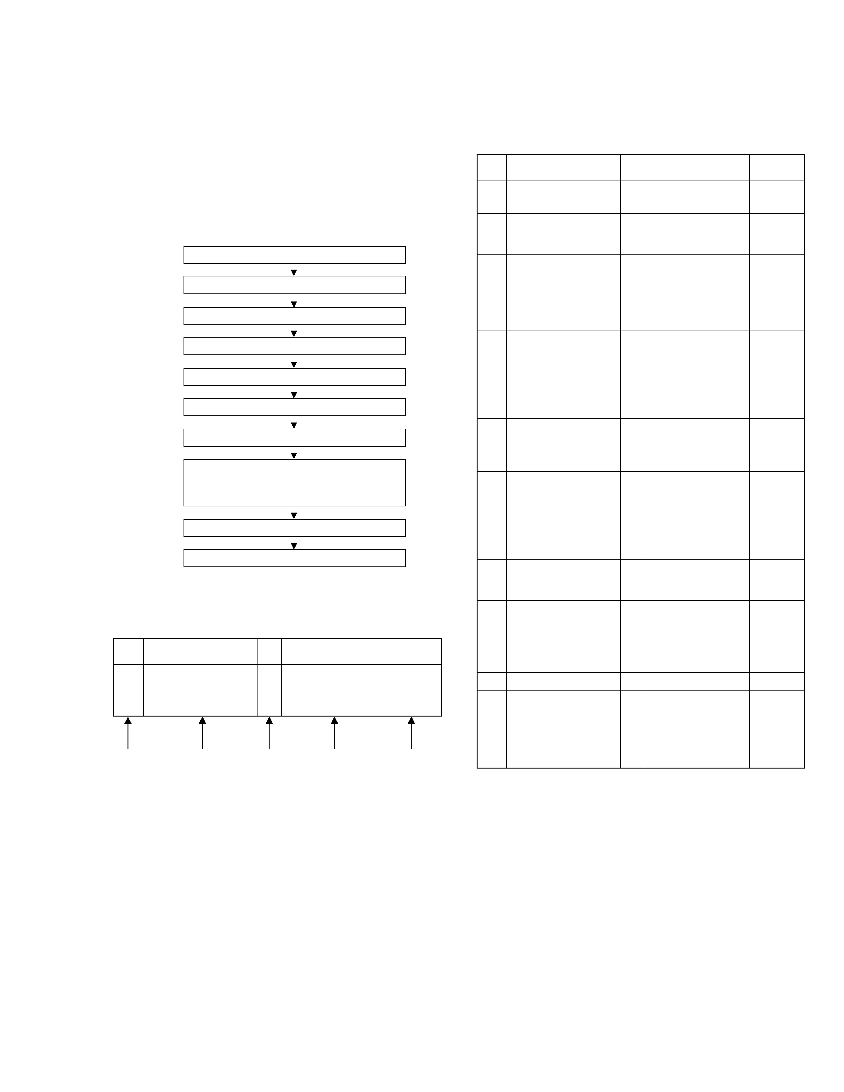
1.1 Disassembly flow chart
This flowchart lists the disassembling steps for the cabinet
parts and P.C. boards in order to gain access to item(s) to
be serviced. When reassembling, perform the step(s) in re-
verse order. Bend, route and dress the flat cables as they
were originally laid.
1.2 How to read the disassembly and assembly
Note:
·
The bracketed ( ) WR of the connector symbol are as-
signed nos. in priority order and do not correspond to
those on the spare parts list.
(5) Adjustment information for installation
Top cover, Bracket
Front panel assembly
SW.REG board assembly
Digital board assembly
D-PRE/REC board assembly
Drum assembly
Mechanism assembly
REC safety board assembly,
Display board assembly,
Jack board assembly
Main board assembly
Bottom cover
[1]
[2]
[3]
[4]
[5]
[6]
[7]
[8]
[9]
[10]
Step/
LocNo.
Part Name
Fig.
No.
Point
Note
-----------------
(1)
(2)
(3)
(4)
(5)
Step/
LocNo.
Part Name
Fig.
No.
Point
Note
[1]
Top cover,
D1 4(S1a),(S1b),3(L1a),
<Note 1a>
2(SD1a),(P1a),(W1a),
CN1(WR1a),
Bracket
2(S1c)
<Example>
(1) Order of steps in Procedure
When reassembling, perform the step(s) in the reverse order.
These numbers are also used as the identification (location) No.
of parts Figures.
(2) Part name to be removed or installed.
(3) Fig. No. showing procedure or part location.
(4) Identification of part to be removed, unhooked, unlocked,
released, unplugged, unclamped or unsoldered.
P= Spring, W= Washer, S= Screw, L= Locking tab, SD= Solder,
CN**(WR**)= Remove the wire (WR**) from the connector
(CN**).
-----------------
-----------------
-----------------
-----------------
-----------------
-----------------
-----------------
-----------------