No.51968
AV32T25EKS / AV32R25EKS
AV32T55EKS / AV32R250EKS
AV32T25EIS
1
COPYRIGHT © 2002 VICTOR COMPANY OF JAPAN, LTD.
May 2002
AV32T25EKS / AV32R25EKS
AV32T55EKS / AV32R250EKS
AV32T25EIS
CONTENTS
!
SPECIFICATIONS
2
! SAFETY PRECAUTIONS
4
!
WARNING
4
!
FEATURES
5
! MAIN DIFFERENCE LIST
5
!
SPECIFIC SERVICE INSTRUCTIONS
6
!
SERVICE ADJUSTMENTS
14
! PARTS LIST
31
STANDARD CIRCUIT DIAGRAM
2-1
SERVICE MANUAL
COLOUR TELEVISION
BASIC CHASSIS
JL
No.51968
AV32T25EKS / AV32R25EKS
AV32T55EKS / AV32R250EKS
AV32T25EIS
2
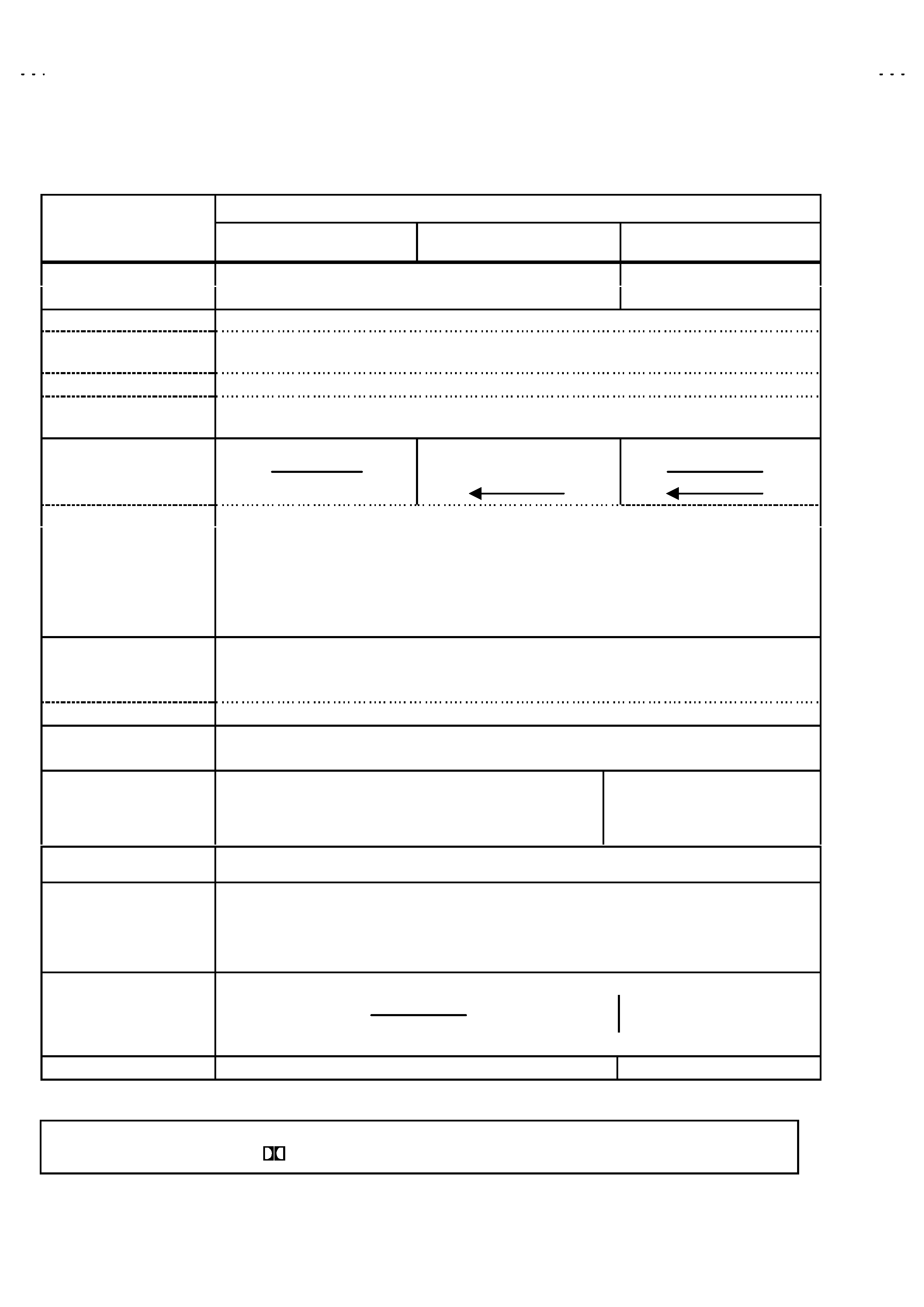
SPECIFICATIONS
Content
Item
AV32T25EKS
AV32T55EKS
AV32T25EIS
AV32R25EKS
AV32R250EKS
Dimensions ( W×
×
×
×H×
×
×
×D )
946mm× 561.5mm×547mm
946mm×561.5mm×551mm
Mass
54.5kg
57.5kg
TV RF System
CCIR ( I )
Colour System
PAL
NTSC (Only in EXT mode)
Stereo System
NICAM
Teletext System
FLOF (Fastext)
WST(Standard system)
Receiving Frequency
VHF
47MHz 470MHz
UHF 470MHz 862MHz
Intermediate Frequency
VIF Carrier 38.9MHz ( I )
SIF Carrier 32.9MHz ( 6.0MHz:I )
Colour Sub Carrier Freq.
PAL 4.43MHz
NT SC 3.58MHz / 4.43MHz
Power Input
AC 220V240V , 50Hz
Power Consumption
200W(Max) / 127W(Avg)
Standby : 3W
Aerial Input Term
75unbalanc ed, Coaxial
Picture Tube
Visible size : 76cm, Meas ured diagonally
High Voltage
31.0kV
(CRT cut off , FULL mode)
Speaker
6.5cm×13cm Oval type×2
6.5cm×13cm Oval type×2(side)
4cm× 16cm Oval type×1 (center)
13cm Round type×1 (sub woofer)
Au dio Output
10W + 10W
10W + 10W + 10W + 18W
EXT-1/EXT-2/EXT-3
(Input / Output)
21-pin Euro c onnector
(SCART socket)
EXT-4 (Input)
Video
1Vp-p 75(RCA pin jack)
Au dio (L/R) 500mVrms( -4dBs ), High Impedance ( RCA pin jack )
S / Video Y : 1Vp-p POSITIVE (Negative sync Provided, when terminated with 75)
C : 0.286Vp-p (Burst signal, when terminated with 75)
AUDIO OUT (Variable)
01Vrms, Low Impedance (RCA pin jack×2)
SURROUND REAR output
7.5W + 7.5W , Impedance 8
(Push terminal)
Headphone jack
Stereo mini jac k (3.5mm )
Remote Control Unit
RM-C55H
RM-C60H
Design & specifications are subject to change without notice.
[AV32R25EKS / AV32R250EKS only]
Manufactured under lic ens e from Dolby Laboratories Licensing Corporation.
"Dolby"and the double-D s ymbol
are trademarks of Dolby Laboratories Licensing Corporation.
+1kV
-1. 5kV
No.51968
AV32T25EKS / AV32R25EKS
AV32T55EKS / AV32R250EKS
AV32T25EIS
3
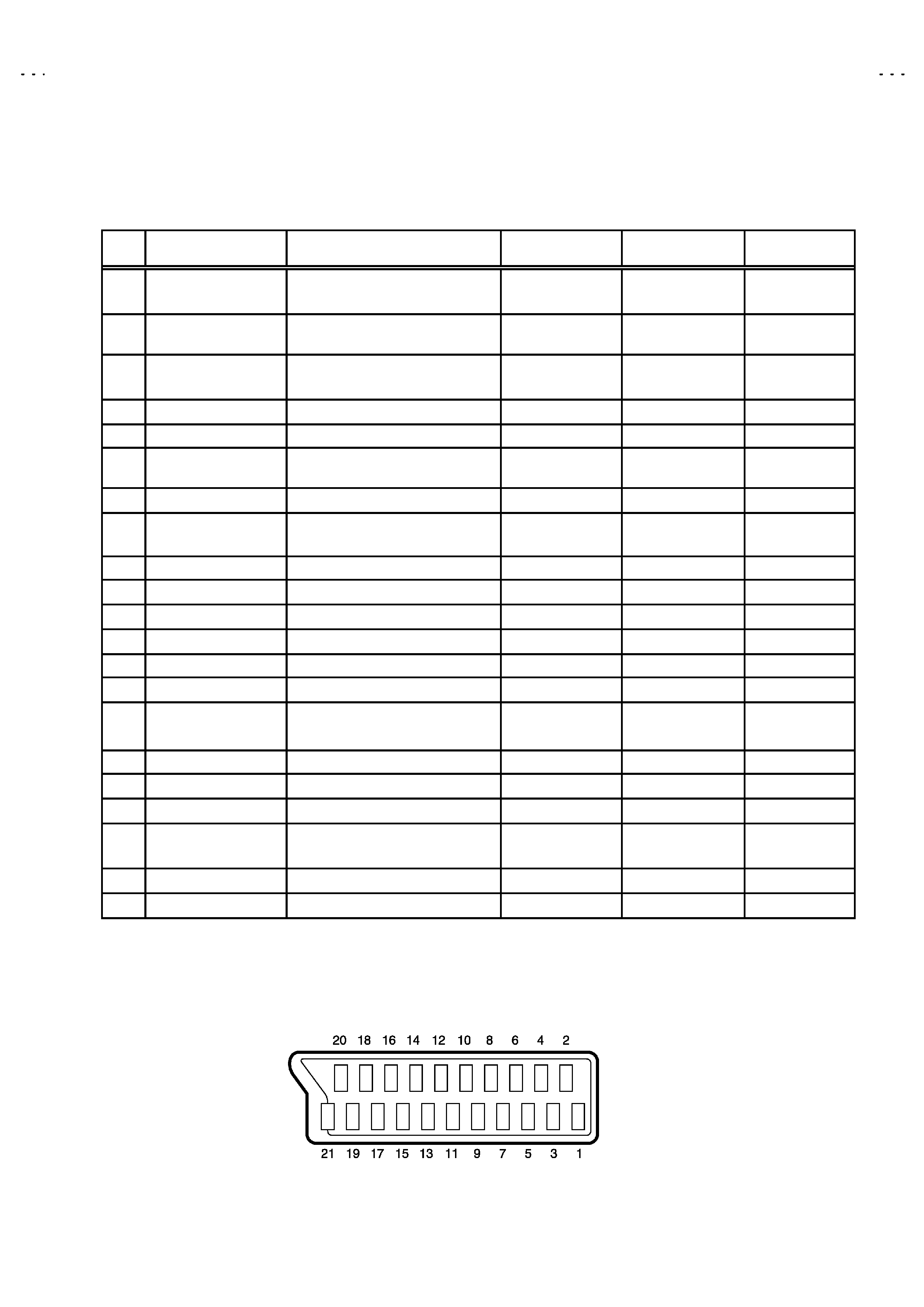
21-pin Euro connector (SCART socket) : EXT-1 / EXT-2 / EXT-3
(P-P= Peak to Peak, S-W= Sync tip to white peak, B-W= Blanking to white peak)
Pin
No .
Signal Designation
Matching Value
EXT-1
EXT-2
EXT-3
1
AUDIO R output
500mVrms(Nominal),
Low impedanc e
(TV OUT)
(LINE OUT)
NC
2
AUDIO R input
500mVrms(Nominal),
High impedance
3
AUDIO L output
500mVrms(Nominal),
Low impedanc e
(TV OUT)
(LINE OUT)
NC
4
AUDIO GND
5
GND (B)
6
AUDIO L input
500mVrms(Nominal),
High impedance
7B input
700mV
B-W, 75
NC
NC
8
FUNCTON SW
(SLOW SW)
Low : 0-3V, High : 8-12V, High
impedanc e
9
GND (G)
10
SCL3
NC
NC
11
G input
700mV
B-W, 75
NC
NC
12
SDA3
NC
NC
13
GND (R)
14
GND (YS)
NC
NC
15
R / C input
R : 700mV
B-W, 75
C : 300mVP-P, 75
(only R)
(only C)
(only C)
16
Ys input
Low : 0 - 0.4, High : 1 - 3V, 75
NC
NC
17
GND(VIDEO output)
18
GND(VIDEO input)
19
VIDEO output
1VP-P(Negative going sync ), 75
(TV)
(LINE OUT)
NC
20
VIDEO / Y input
1V
P-P(Negative going sync ), 75
21
COMMON GND
[Pin assignment]

No.51968
AV32T25EKS / AV32R25EKS
AV32T55EKS / AV32R250EKS
AV32T25EIS
4
SAFETY PRECAUTIONS
1. The design of this product c ontains special hardware and many
circuits and components specially for safety purposes. For
continued protection, no changes should be made to the original
design unless authorized in writing by the manufacturer.
Replacement parts must be identic al to thos e used in the original
circuits. Service should be performed by qualified pers onnel
only.
2. Alterations of the design or circ uitry of the product should not be
made. Any design alterations or additions will void the
manufacturer's warranty and will further relieve the manufacturer
of responsibility for personal injury or property damage resulting
therefrom.
3. Many electrical and mechanical parts in the product have special
safety-related characteristics. Thes e characteristics are often not
evident from visual inspection nor c an the protection afforded by
them necess ary be obtained by using replac ement c omponents
rated for higher voltage, wattage, etc. Replacement parts whic h
have these special safety c harac teristic s are identified in the
Parts List of Service Manual. Electrical components having suc h
features are identified by shading on the schematic s and by (!)
on the Parts List in the Service Manual. The use of a substitute
replac ement
which
does
not have
the s ame
safety
characteristics as the recommended replacement part shown in
the Parts List of Service Manual may cause shock, fire, or other
hazards.
4. The leads in the products are routed and dressed with ties,
clamps, tubing's, barriers and the like to be s eparated from live
parts, high temperature parts, moving parts and / or sharp edges
for the prevention of electric shock and fire hazard. When
service is required, the original lead routing and dress should be
observed, and it should be confirmed that they have been
returned to normal, after re-assembling.
WARNING
1. The equipment has been designed and manufactured to meet international safety standards.
2. It is the legal responsibility of the repairer to ensure that thes e s afety standards are maintained.
3. Repairs must be made in acc ordance with the relevant safety standards .
4. It is essential that safety critical c omponents are replac ed by approved parts.
5. If mains voltage selec tor is provided, check s etting for local voltage.
No.51968
AV32T25EKS / AV32R25EKS
AV32T55EKS / AV32R250EKS
AV32T25EIS
5
FEATURES
" By preferenc e, users can select the picture size from REGULAR,
PANORAMIC, FULL, 14:9 ZOOM, 16:9 ZOOM, 16:9 ZOOM SUB
TITLE modes. When the TV unit received WSS picture signal, the
picture can be changed to 16:9 ZOOM mode automatic ally.
"
The TELETEXT SYSTEM has a built-in FASTEXT, and WST
system.
"
Becaus e this TV unit corresponds to multiplex broadcast, users
can enjoy music programs and s porting events with live realism.
In addition, BILINGUAL programs can be heard in their original
language.
"
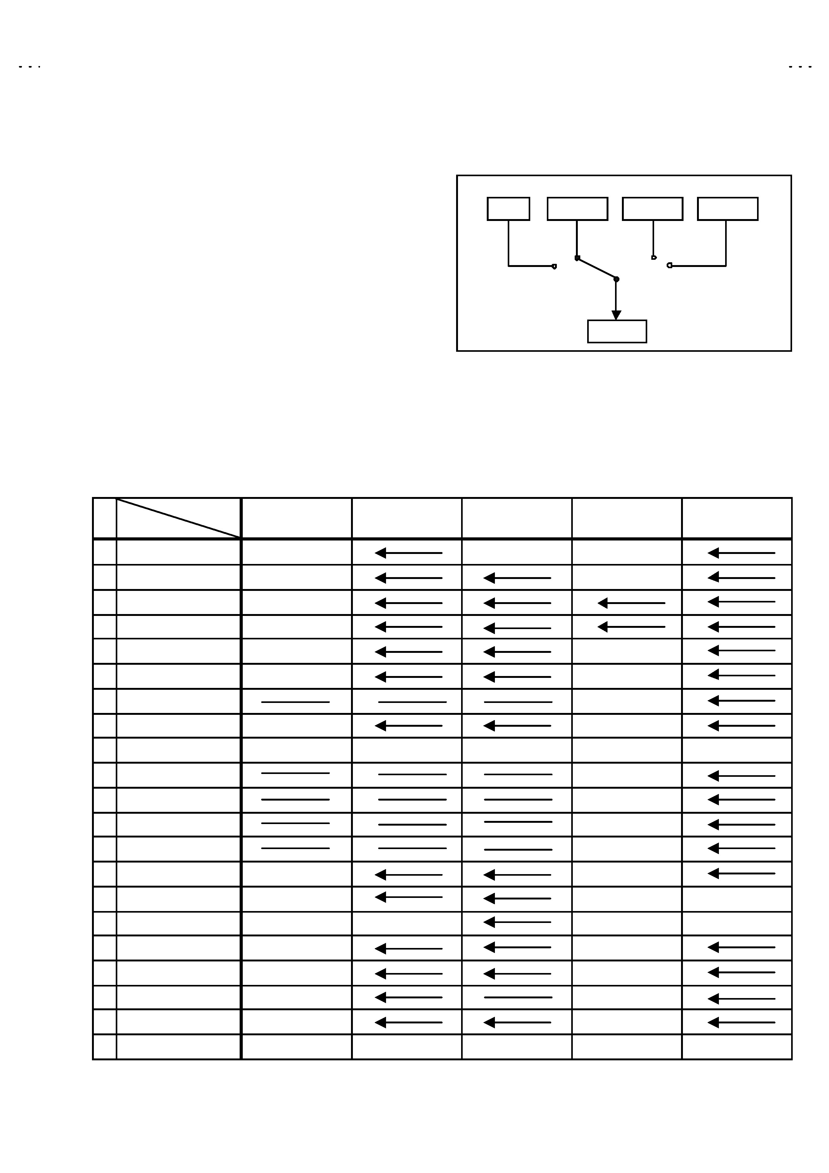
Users can make VCR dubbing of picture and sound by controlling
the AV selec tor to select an optional sourc e at the EXT-2 output
shown in figure.
" Built-inn DOLBY PRO LOGIC 3D-PHONE func tion.
[Only AV32R25EKS / AV32R250EKS]
MAIN DIFFERENCE LIST
!
!
!
!
Model Name
Part Name
AV32T25EKS
AV32T55EKS
AV32T25EIS
AV32R25EKS
AV32R250EKS
MAIN PB ASSY
SJL-1004A-U2
SJL-1007A-U2
SJL-1008A-U2
DEF POW ER PB ASS
SJL-2002A-U2
SJL-2004A-U2
CRT SKT PB ASSY
SJL-3002A-U2
FRONT CT RL ASSY
SJL-8004A-U2
SIDE CTRL ASSY
SJL-8104A-U2
SJL-8102A-U2
AV SW PB ASSY
SJL0S002A-U2
SJL0S003A-U2
DOLBY PB ASSY
SJL0D001A-U2
!
!
!
! AV BOARD
LC11010-004A-U
LC11336-001B-U
!
!
!
! RATING LABEL
LC11364-004A-U
LC11364-014A-U
LC11364-017A-U
LC11364-002A-U
LC11364-015A-U
!
!
!
! SP BOX T
LC11308-001A-U
!
!
!
! SP BOX B
LC11309-001A-U
SPEAKER (SP03)
QAS0110-001
SPEAKER (SP04)
QAS0092-001
SPEAKER PANEL
LC21065-001A-U
LC21031-001A-U
!
!
!
! F CABI ASSY
LC11360-002B-U
LC11360-001B-U
LC11360-001A-U
JVC MARK
LC41250-002C-C
LC41250-001A-C
LC41250-002C-C
LC41250-001A-C
CUSHION ASSY
LC11373-001A
LC11361-001A
!
!
!
! INST BOOK
LCT1153-001A-U
LCT1152-001A-U
REG CARD
AEM3148-001-E
AEM3148-001-E
RC HAND UNIT
RM-C55H-1C
RM-C60H-1C
EURO LABEL
AEM1064-006-E
AEM1064-029-E
AEM1064-008-E
AEM1064-001-E
AEM1064-016-E
TV
EXT-1
EXT-3
EXT-2
EXT-4