No.51943
AV32T20EPS
AV28T20EPS
AV28T200EPS
1
COPYRIGHT © 2002 VICTOR COMPANY OF JAPAN, LTD.
Apr. 2002
AV32T20EPS
AV28T20EPS
AV28T200EPS
CONTENTS
! SPECIFICATIONS
2
!
SAFETY PRECAUTIONS
4
! FEATURES
5
!
MAIN DIFFERENCE LIST
5
! SPECIFIC SERVICE INSTRUCTIONS
6
! SERVICE ADJUSTMENTS
12
!
PARTS LIST
31
STANDARD CIRCUIT DIAGRAM
2-1
SERVICE MANUAL
COLOUR TELEVISION
BASIC CHASSIS
JL
No.51943
AV32T20EPS
AV28T20EPS
AV28T200EPS
2
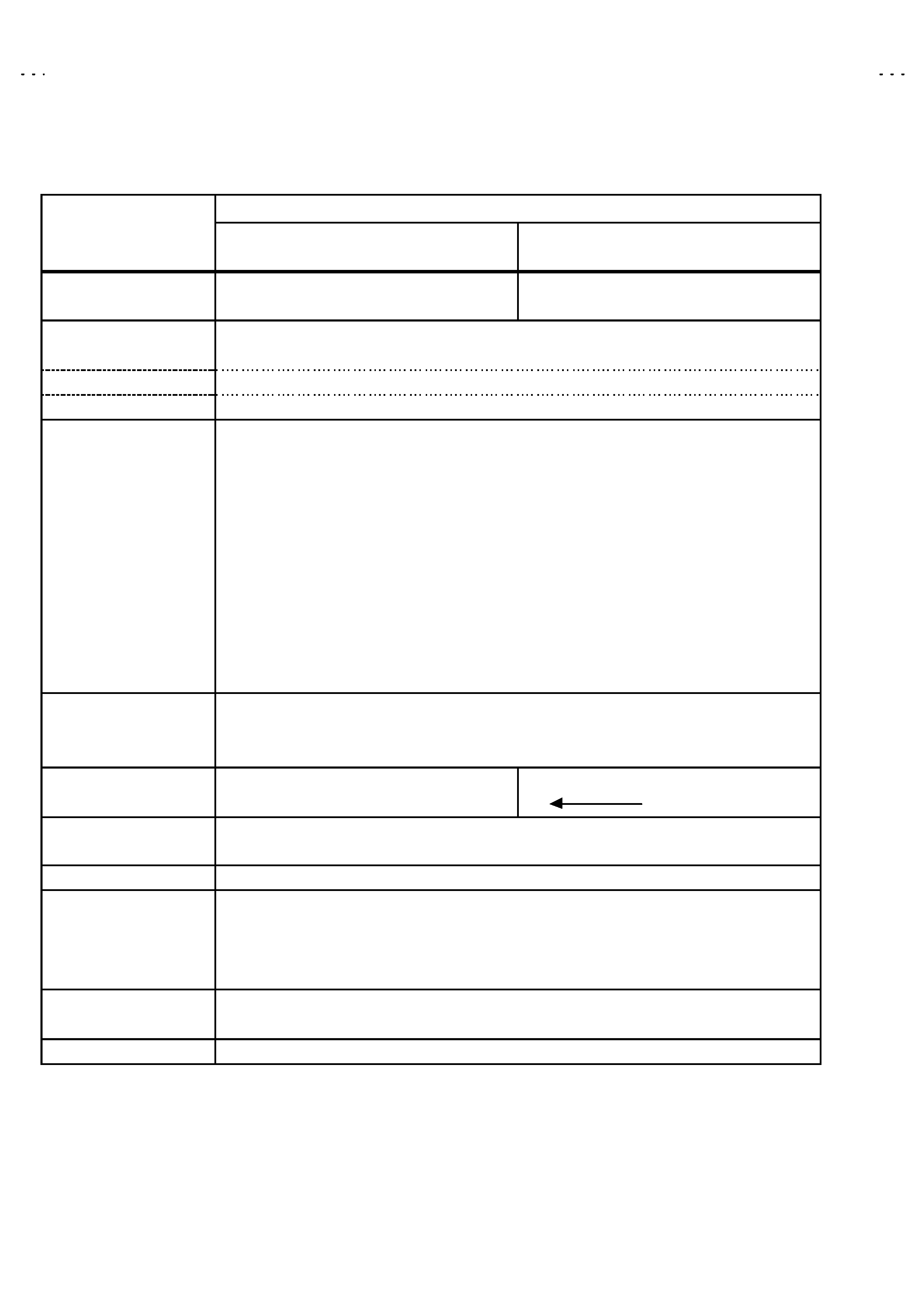
SPECIFICATIONS
Content
Item
AV28T20EPS
AV28T200EPS
AV32T20EPS
Dimensions ( W×
×
×
×H×
×
×
×D )
780mm× 509mm×499mm
855mm×550mm×568mm
Mass
38.6kg
54.7kg
TV RF System
CCIR ( B/G , I , L , L')
Colour System
PAL , SECAM , NTSC3.58 / NTSC4.43(Only EXT mode)
Stereo System
A2(B/G) / NICAM(B/G , I , L)
Teletext System
FLOF (Fastext) , TOP (German system), WST (World Standard sys tem)
Receiving Frequency
VHF 47MHz 470MHz
UHF 470MHz 862MHz
French CAT V 116MHz 172MHz / 220MHz 469MHz
Intermediate Frequency
VIF Carrier 38.9MHz (B/G , I , L) / 33.9MHz (L')
SIF Carrier 33.4MHz (5.5MHz:B/G) / 32.9MHz (6.0MHz:I) /32.4MHz (6.5MHz :L) /40.4MHz (6.5MHz:L')
Colour Sub Carrier Freq.
PAL 4.43MHz
SECAM 4.25MHz / 4.40625MHz
NT SC 3.58MHz / 4.43MHz
Power Input
AC 220V240V , 50Hz
Power Consumption
180W(Max) / 120W(Avg) , 3W(Stand by)
Aerial Input Term
75unbalanc ed, Coaxial
Picture Tube Size
Visible size : 66cm, Meas ured diagonally
Visible size : 76cm, Meas ured diagonally
High Voltage
31.0kV
(at zero beam c urrent)
Speaker
4cm×16cm Oval type× 2
Au dio Output
10W + 10W
EXT-1/EXT-2/EXT-3
21-pin Euro c onnector
EXT-4 (Input)
Video
1Vp-p 75(RCA pin jack)
Au dio (L/R) 500mVrms( -4dBs ), High Impedance ( RCA pin jack )
S / Video Y : 1Vp-p POSITIVE (Negative sync Provided, when terminated with 75)
C : 0.286Vp-p (Burst signal, when terminated with 75)
AUDIO OUT (Variable)
01Vrms, Low Impedance (RCA pin jack×2)
Headphone jack
Stereo mini jac k (3.5mm )
Remote Control Unit
RM-C54H-1C (AAA/R03 dry battery×2)
Design & specifications are subject to change without notice.
+1kV
-1. 5kV
No.51943
AV32T20EPS
AV28T20EPS
AV28T200EPS
3
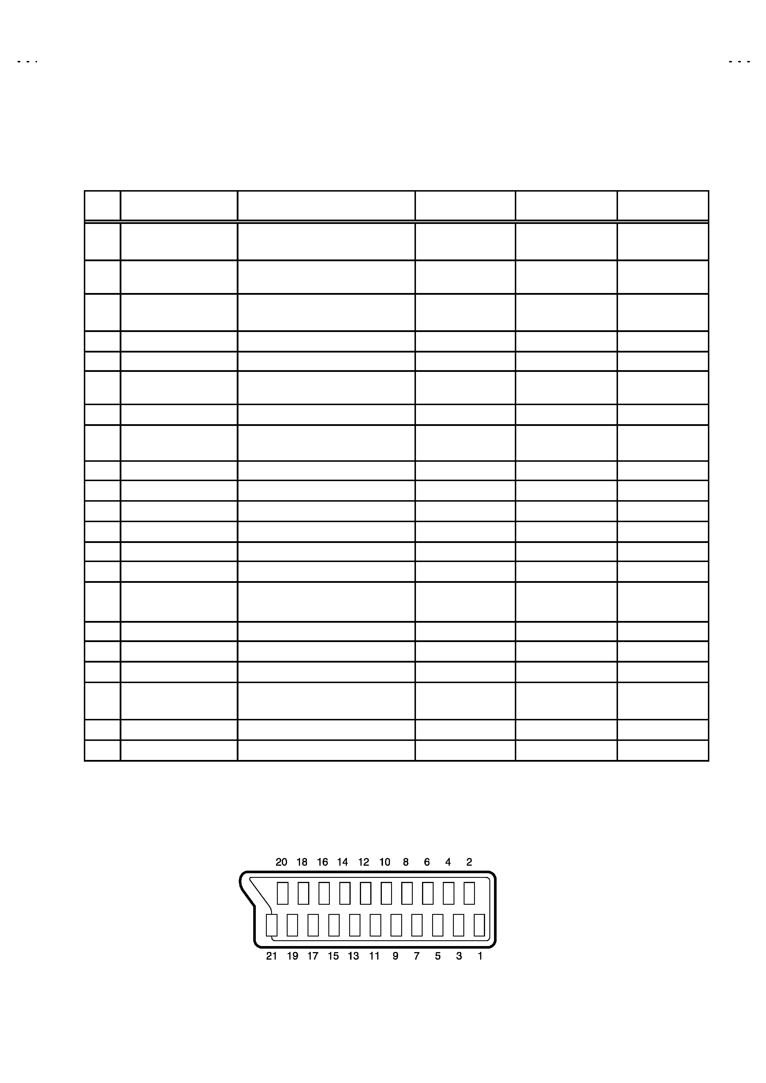
21-pin Euro connector (SCART socket) : EXT-1 / EXT-2 / EXT-3
(P-P= Peak to Peak, S-W= Sync tip to white peak, B-W= Blanking to white peak)
Pin
No .
Signal Designation
Matching Value
EXT-1
EXT-2
EXT-3
1
AUDIO R output
500mVrms(Nominal),
Low impedanc e
(TV OUT)
(LINE OUT)
NC
2
AUDIO R input
500mVrms(Nominal),
High impedance
3
AUDIO L output
500mVrms(Nominal),
Low impedanc e
(TV OUT)
(LINE OUT)
NC
4
AUDIO GND
5
GND (B)
6
AUDIO L input
500mVrms(Nominal),
High impedance
7B input
700mV
B-W, 75
NC
NC
8
FUNCTON SW
(SLOW SW)
Low : 0-3V, High : 8-12V, High
impedanc e
9
GND (G)
10
SCL3
NC
NC
11
G input
700mV
B-W, 75
NC
NC
12
SDA3
NC
NC
13
GND (R)
14
GND (YS)
NC
NC
15
R / C input
R : 700mV
B-W, 75
C : 300mVP-P, 75
(only R)
(only C)
(only C)
16
Ys input
Low : 0 - 0.4, High : 1 - 3V, 75
NC
NC
17
GND(VIDEO output)
18
GND(VIDEO input)
19
VIDEO output
1VP-P(Negative going sync ), 75
(TV)
(LINE OUT)
NC
20
VIDEO / Y input
1V
P-P(Negative going sync ), 75
21
COMMON GND
[Pin assignment]
No.51943
AV32T20EPS
AV28T20EPS
AV28T200EPS
4
SAFETY PRECAUTIONS
1. The design of this product contains special hardware, many
circuits and components specially for safety purposes. For
continued protection, no changes should be made to the original
design unless authorized in writing by the manufacturer.
Replacement parts must be identic al to thos e used in the original
circuits. Servic e should be performed by qualified personnel
only.
2. Alterations of the design or circuitry of the products should not be
made. Any design alterations or additions will void the
manufacturer's warranty and will further relieve the manufacturer
of responsibility for personal injury or property damage resulting
therefrom.
3. Many electrical and mechanical parts in the products have
special safety-related characteristics. T hese characteristics are
often not evident from visual inspection nor can the protection
afforded by them necessarily be obtained by using replacement
components rated for higher voltage, wattage, etc. Replacement
parts whic h have these special s afety characteristics are
identified in the parts list of Servic e manual. Electrical
components having su ch features are identified by shading
on the schematics and by (!
!
!
!
) on the parts list in Service
manual. The us e of a substitute replacement which does not
have the same safety characteristics as the recommended
replac ement part shown in the parts list of Service manual may
cause shock, fire, or other hazards .
4. Do n't short between the LIVE side ground and ISOL ATED
(NEUTRAL) side ground or EARTH side ground when
repairing.
Some model's power circuit is partly different in the GND. T he
differenc e of the GND is shown by the LIVE : (") side GND, the
ISOLATED(NEUTRAL) : (#) side GND and EARTH : ($) side
GND. Don't short between the LIVE side GND and
ISOLATED(NEUTRAL) side GND or EARTH side GND and
never measure with a measuring apparatus (oscilloscope etc.)
the LIVE side GND and ISOLATED(NEUTRAL) side GND or
EARTH side GND at the s ame time.
If above note will not be kept, a fuse or any parts will be broken.
5. If any repair has been made to the chassis, it is recommended
that the B1 setting should be checked or adjusted (See
ADJUSTMENT OF B1 POWER SUPPLY).
6. The high voltage applied to the picture tube must conform with
that specified in Service manual. Excessive high voltage can
cause an increase in X-Ray emission, arcing and possible
component damage, therefore operation under excessive high
voltage conditions should be k ept to a minimum, or should be
prevented. If s evere arc ing occurs, remove the AC power
immediately and determine the cause by visual inspection
(incorrect installation, cracked or melted high voltage harness,
poor soldering, etc.). To maintain the proper minimum level of
soft X-Ray emission, c omponents in the high voltage circuitry
including the picture tube must be the exact replacements or
alternatives approved by the manufacturer of the c omplete
product.
7. Do not c hec k high voltage by drawing an arc. Use a high voltage
meter or a high v oltage probe with a VTVM. Dis charge the
picture tube before attempting meter connection, by c onnecting
a clip lead to the ground frame and c onnecting the other end of
the lead through a 10k
2W resistor to the anode button.
8. When service is required, observe the original lead dress. Extra
prec aution should be given to assure correct lead dress in the
high voltage circuit area. W here a s hort circuit has occurred,
those components that indicate evidence of overheating should
be replaced. Always use the manufacturer's replacement
components.
9. Isolation Check
(Safety for Electrical Shock Hazard)
After re-ass embling the product, always perform an isolation
check on the exposed metal parts of the cabinet (antenna
terminals, video/audio input and output terminals, Control knobs,
metal cabinet, screwheads, earphone jack , control shafts, etc.)
to be sure the product is s afe to operate without danger of
electrical shoc k.
(1) Dielectric Strength Test
The isolation between the AC primary circuit and all metal parts
exposed to the us er, particularly any expos ed metal part having a
return path to the chass is should withs tand a voltage of 3000V
AC (r.m.s.) for a period of one sec ond.
(. . . . Withstand a voltage of 1100V AC (r.m.s.) to an applianc e
rated up to 120V, and 3000V AC (r.m.s.) to an appliance rated
200V or more, for a period of one second.)
This method of test requires a test equipment not generally found
in the servic e trade.
(2) Leakage Current Check
Plug the AC line c ord directly into the AC outlet (do not use a line
isolation transformer during this check.). Using a " Leakage
Current Tester", measure the leakage current from each exposed
metal part of the cabinet, particularly any expos ed metal part
having a return path to the chassis , to a known good earth
ground (water pipe, etc.). Any leakage current must not exceed
0.5mA AC (r.m.s.).
However, in tropic al area, this must not exceed 0.2mA AC
(r.m.s.).
"
"
"
"
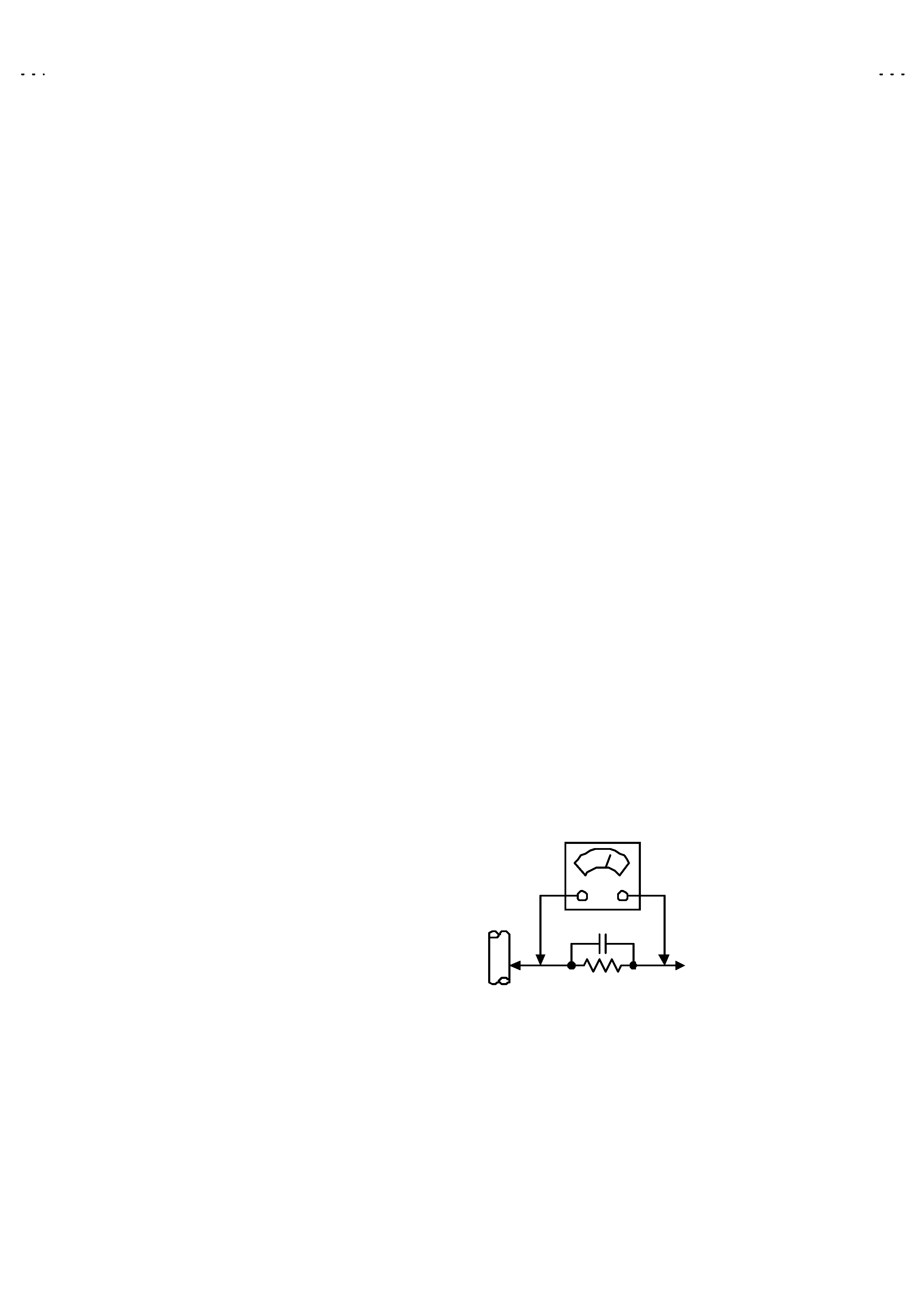
Alternate Check Method
Plug the AC line c ord directly into the AC outlet (do not use a line
isolation transformer during this check.). Use an AC voltmeter
having 1000 ohms per volt or more sens itivity in the following
manner. Connec t a 1500
10W res istor paralleled by a 0.15µF
AC-type c apacitor between an exposed metal part and a known
good earth ground (water pipe, etc.). Meas ure the AC voltage
across the res istor with the AC voltmeter. Move the resistor
connec tion to each exposed metal part, particularly any exposed
metal part having a return path to the chassis, and measure the
AC voltage ac ross the res istor. Now, reverse the plug in the AC
outlet and repeat eac h measurement. Any voltage measured
must not exc eed 0.75V AC (r.m.s.). This c orresponds to 0.5mA
AC (r.m.s.).
However, in tropical area, this must not exceed 0.3V AC ( r.m.s.).
This corresponds to 0.2mA AC (r.m.s.).
0.15F AC-TYPE
1500
10W
GOOD EARTH GROUND
PLACE THIS PROBE
ON EACH EXPOSED
METAL PART
AC VOLTMETER
(HAVING 1000
/V,
OR MOR E SENSITIVITY)
No.51943
AV32T20EPS
AV28T20EPS
AV28T200EPS
5
FEATURES
" By preferenc e, users can select the picture size from REGULAR,
PANORAMIC, FULL, 14:9 ZOOM, 16:9 ZOOM, 16:9 ZOOM SUB
TITLE modes. When the TV unit received WSS picture signal, the
picture can be changed to 16:9 ZOOM mode automatic ally.
"
The TELETEXT SYSTEM has a built-in FASTEXT, TOP and
WST system.
"
Becaus e this TV unit corresponds to multiplex broadcast, users
can enjoy music programs and s porting events with live realism.
In addition, BILINGUAL programs can be heard in their original
language.
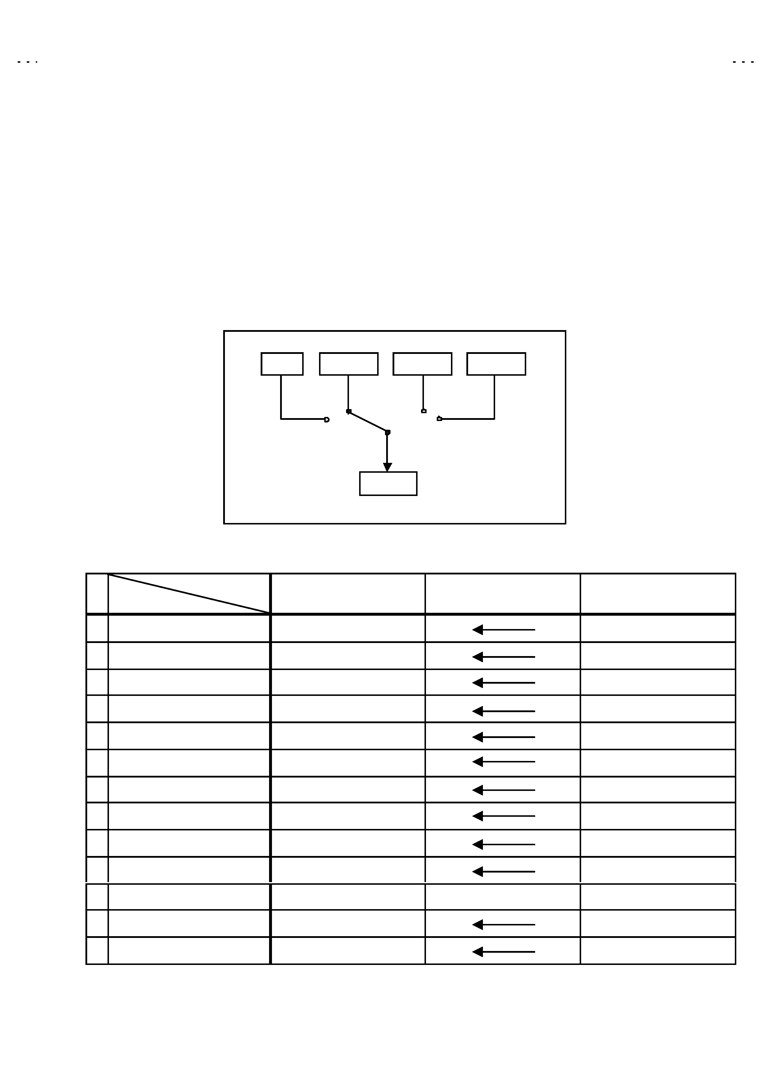
" Users can make VCR dubbing of picture and sound by controlling
the AV selec tor to select an optional sourc e at the EXT-2 output
shown in figure.
MAIN DIFFERENCE LIST
!
!
!
!
Model Name
Part Name
AV28T20EPS
AV28T200EPS
AV32T20EPS
MAIN PWB
SJL-1001A-U2
SJL-1003A-U2
DEF POWER PWB
SJL-2001A-U2
SJL-2002A-U2
CRT SKT PWB
SJL-3001A-U2
SJL-3002A-U2
FRONT CTRL PWB
SJL-8001A-U2
SJL-8002A-U2
! PICTURE TUBE (ITC)
W66QDE993X987
W76QDD257X08
! DEG COIL
QQW0137-001
QQW0105-001
! F. CABINET ASSY
LC10662-022A-U
LC10376-018A-U
! CONTROL BASE (1/2)
LC10380-003B-U
LC10380-001C-U
! CONTROL BASE (2/2)
LC10380-004B-U
LC10380-002B-U
! REAR COVER
LC10664-003B-U
LC10378-004B-U
! RATING LABEL
LC20780-018A-U
LC20780-019A-U
LC20542-008A-U
PACKING CASE
AEM1002-B68-E
AEM1002-B70-E
CUSHION ASSY
LC10722-002A-U
LC10384-002C-U
TV
EXT-1
EXT-3
EXT-2
EXT-4