COLOR MONITOR
CKB5237L
CKB7227L
Manual
SERVICE
COLOR MONITOR
CONTENTS
+
MENU
EXIT
1. Precautions
2. Product Specifications
3. Operating Instructions
4. Disassembly & Reassembly
5. Alignment & Adjustments
6. Troubleshooting
7. Exploded View & Parts List
8. Block Diagram
9. Wiring Diagram
10. PCB Diagrams & Electrical Parts List
11. Schematic Diagrams

Samsung Electronics Co., Ltd. October 1997
Printed in Korea
Code No.: BH68-60934A

1-1-1 Warnings
1. For continued safety, do not attempt to
modify the circuit board.
2. Disconnect the AC power before servicing.
3. When the chassis is operating, semiconductor
heatsinks are potential shock hazards.
1-1-2
Servicing the High Voltage System and
CRT
WARNING: A high voltage VR replaced in the
wrong direction may cause
excessive X-ray emissions.
Caution: When replacing the high voltage
adjustment VR, it must be fixed by a
soldering iron after it is properly set.
1. When servicing the high voltage system,
remove the static charge by connecting a 10k
ohm resistor in series with an insulated wire
(such as a test probe) between the chassis and
the anode lead. (Disconnect the AC line cord
from the AC outlet.)
2. High Voltage VR Replacement
If the high voltage system requires
adjustment, use the following procedure (all
steps are required):
a. Turn the power off and disconnect the AC
line cord from the power source.
b. Unsolder and remove the high voltage VR
on the Main PCB.
c. Replace the VR and adjust the high voltage
to the specification.
d. Using a soldering iron, melt the adjustment
cap on the high voltage VR to prevent any
movement.
3. It is essential that service technicians have an
accurate high voltage meter available at all
times. Check the calibration of this meter
periodically.
4. When troubleshooting a monitor with
excessively high voltage, avoid being
unnecessarily close to the monitor. Do not
operate the monitor for longer than is
necessary to locate the cause of excessive
voltage.
5. High voltage should always be kept at the
rated value, no higher. Be sure all service
personnel are aware of the procedures and
instructions covering X-rays.
The only potential source of X-ray in current
solid state display monitors is the tube.
However, the CRT does not emit measurable
X-ray radiation if the high voltage is at the
high voltage adjustment value.
Only when high voltage is excessive are
X-rays capable of penetrating the shell of the
CRT, including the lead in glass material.
Operation at high voltages may also cause
failure of the CRT or high voltage circuitry.
6. When the high voltage regulator is operating
properly, there is no possibility of an X-ray
problem. Test the brightness and use a meter
to monitor the high voltage each time a color
monitor comes in for service. Make sure the
high voltage does not exceed its specified
value and that it is regulating correctly.
7. The CRT is especially designed to prohibit
X-ray emissions. To ensure continued X-ray
protection, replace the CRT with only one that
is the same or equivalent type as the original.
Carefully reinstall the CRT shields and
mounting hardware; these also provide X-ray
protection.
8. Handle the CRT only when wearing
shatterproof goggles and after completely
discharging the high voltage anode.
9. Do not lift the CRT by the neck.
CKB5237L/7227L
1-1
1 Precautions
Follow these safety, servicing and ESD precautions to prevent damage and to protect against potential
hazards such as electrical shock and X-rays.
1-1 Safety Precautions
1-1-3 Fire and Shock Hazard
Before returning the monitor to the user, perform
the following safety checks:
1. Inspect each lead dress to make certain that
the leads are not pinched or that hardware is
not lodged between the chassis and other
metal parts in the monitor.
2. Inspect all protective devices such as
nonmetallic control knobs, insulating
materials, cabinet backs, adjustment and
compartment covers or shields, isolation
resistor-capacitor networks, mechanical
insulators, etc.
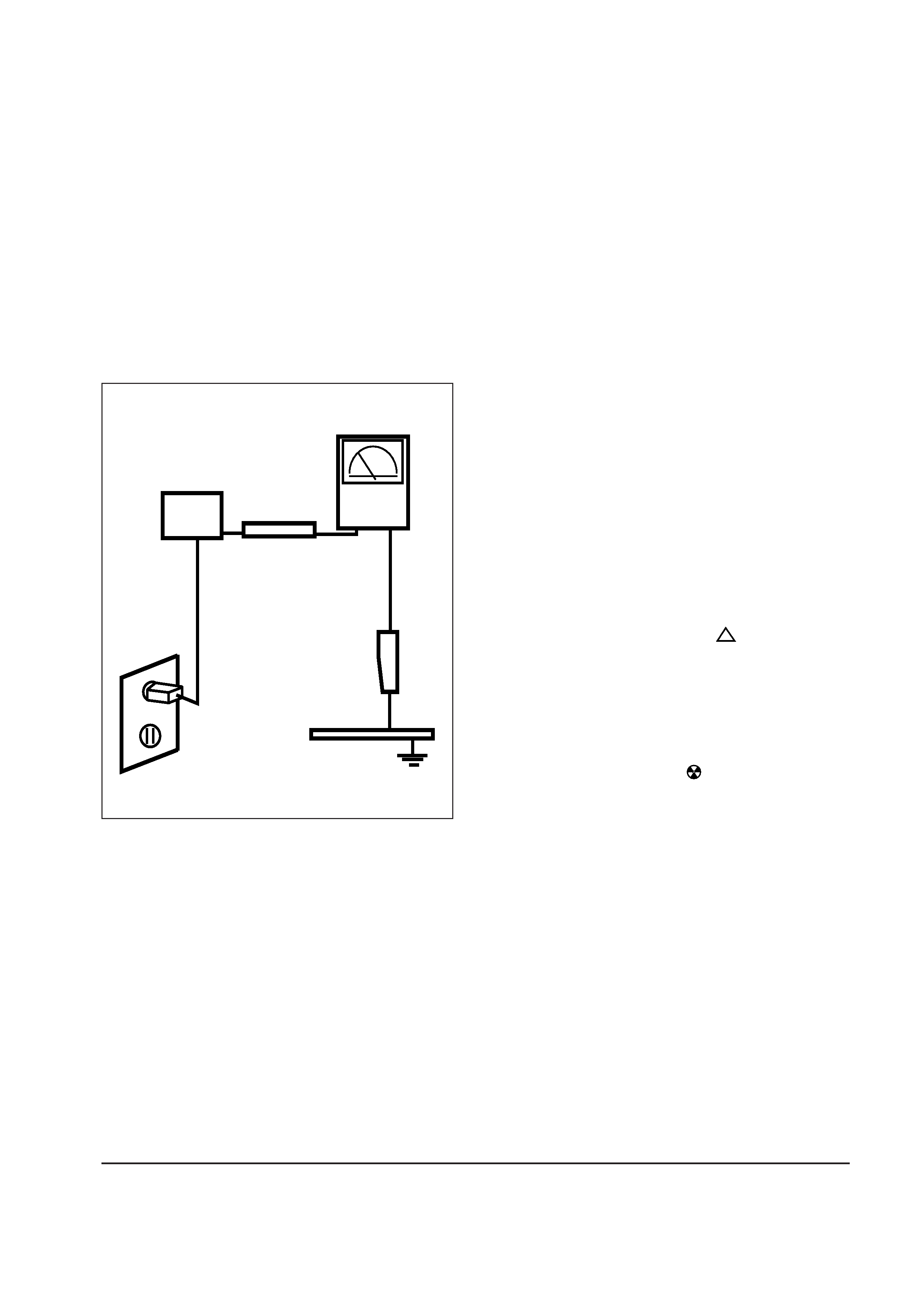
Figure1-1. Leakage Current Test Circuit
3. Leakage Current Hot Check (Figure 1-1):
WARNING: Do not use an isolation transformer
during this test.
Use a leakage current tester or a metering
system that complies with American National
Standards Institute (ANSI C101.1, Leakage
Current for Appliances), and Underwriters
Laboratories (UL Publication UL1410, 59.7).
4. With the unit completely reassembled, plug
the AC line cord directly into a 120V AC
outlet. With the unit's AC switch first in the
ON position and then OFF, measure the
current between a known earth ground (metal
water pipe, conduit, etc.) and all exposed
metal parts, including: metal cabinets,
screwheads and control shafts. The current
measured should not exceed 0.5 milliamp.
Reverse the power-plug prongs in the AC
outlet and repeat the test.
1-1-4 Product Safety Notices
Some electrical and mechanical parts have special
safety-related characteristics which are often not
evident from visual inspection. The protection
they give may not be obtained by replacing them
with components rated for higher voltage,
wattage, etc. Parts that have special safety
characteristics are identified by
on schematics
and parts lists. A substitute replacement that does
not have the same safety characteristics as the
recommended replacement part might create
shock, fire and / or other hazards. Product safety
is under review continuously and new
instructions are issued whenever appropriate.
Components identified by
on schematics and
parts lists must be sealed by a soldering iron after
replacement and adjustment.
1 Precautions
1-2
CKB5237L/7227L
DEVICE
UNDER
TEST
TEST ALL
EXPOSED METAL
SURFACES
(READING SHOULD
NOT BE ABOVE 0.5mA)
LEAKAGE
CURRENT
TESTER
2-WIRE CORD
ALSO TEST WITH
PLUG REVERSED
(USING AC ADAPTER
PLUG AS REQUIRED)
EARTH
GROUND
!

1-2-1 General Servicing Precautions
1. Servicing precautions are printed on the
cabinet, and should be followed closely.
2. Always unplug the unit's AC power cord
from the AC power source before attempting
to:
(a) remove or reinstall any component or
assembly, (b) disconnect PCB plugs or
connectors, (c) connect a test component in
parallel with an electrolytic capacitor.
3. Some components are raised above the
printed circuit board for safety. An insulation
tube or tape is sometimes used. The internal
wiring is sometimes clamped to prevent
contact with thermally hot components.
Reinstall all such elements to their original
position.
4. After servicing, always check that the screws,
components and wiring have been correctly
reinstalled. Make sure that the area around the
serviced part has not been damaged.
5. Check the insulation between the blades of the
AC plug and accessible conductive parts
(examples: metal panels, input terminals and
earphone jacks).
6. Insulation Checking Procedure: Disconnect the
power cord from the AC source and turn the
power switch ON. Connect an insulation
resistance meter (500 V) to the blades of the
AC plug.
The insulation resistance between each blade
of the AC plug and accessible conductive
parts (see above) should be greater than 1
megohm.
7. Never defeat any of the +B voltage interlocks.
Do not apply AC power to the unit (or any of
its assemblies) unless all solid-state heat sinks
are correctly installed.
8. Always connect a test instrument's ground
lead to the instrument chassis ground before
connecting the positive lead; always remove
the instrument's ground lead last.
1 Precautions
CKB5237L/7227L
1-3
1-2 Servicing Precautions
WARNINGS: A high voltage VR replaced in the wrong direction may cause excessive X-ray
emissions.
An electrolytic capacitor installed with the wrong polarity might explode.
Cautions:
Before servicing instruments covered by this service bulletin, read and follow the
Safety Precautions section of this manual.
When replacing the high voltage adjustment VR, it must be fixed by a soldering iron
after it is properly set.
Note:
If unforeseen circumstances create conflict between the following servicing precautions and
any of the safety precautions, always follow the safety precautions.