TV/DVD COMBO
AV-20FD24
No. 52133
2003/06
COPYRIGHT © 2003 VICTOR COMPANY OF JAPAN, LTD.
AV-20FD24
SERVICE MANUAL
CONTENTS
q
SPECIFICATIONS .............................................................................................................................................. 2
q
OPERATING INSTRUCTIONS (APPENDIX)
q
SAFETY PRECAUTIONS .................................................................................................................................. 3
q
SPECIFIC SERVICE INSTRUCTIONS .............................................................................................................. 7
q
SERVICE ADJUSTMENTS .............................................................................................................................. 19
q
GUIDE FOR REPAIRING ................................................................................................................................. 25
q
STANDARD CIRCUIT DIAGRAM ................................................................................................................... 2-1
q
PARTS LIST ..................................................................................................................................................... 37
TV CATV
POWER
DISPLAY
AUDIO
SLEEP
TIMER
PLAY MODE
AUDIO
TITLE
JUMP
ANGLE
MARKER
ZOOM
SLOW +
+
CH
INPUT
CH
VOL
VOL
+
CANCEL
LIGHT
MUTING
TV MENU
DVD SETUP
DVD MENU
TV/DVD
NEXT
PREV
B.SEARCH
F.SEARCH
PLAY
PAUSE/STILL
STOP
OPEN/CLOSE
SELECT
/ENTER
C.C.
123
456
789
0 RETURN
REPEATA-B RETURN
SUBTITLE
TV / DVD

2
AV-20FD24
No. 52133
SPECIFICATIONS
TELEVISION
Picture Tube:
20" (measured diagonally)
Color System:
NTSC
TV RF System:
US System M
Tuner Type:
Quartz PLL Frequency Synthesized
Receiving Channels:
VHF
2-13
UHF
14-69
CATV
14-36 (A)-(W)
37-59 (AA)-(WW)
60-85 (AAA)-(ZZZ)
86-94 (86)-(94)
95-99 (A-5)-(A-1)
100-125 (100)-(125)
01 (5A)
Intermediate Frequency:
Picture (FP) : 45.75 MHz
Sound (FS) : 41.25 MHz
FP-FS :
4.50 MHz
Antenna Input:
VHF/UHF In 75 ohms coaxial, F-Type Connector
Speaker:
1.8" x 3.9", 8 ohms x 2
Audio Output Power:
2.5 W + 2.5 W
DVD/CD PLAYER
Color System:
NTSC
Applicable Disc:
DVD (120 mm, 80 mm)
CD-DA (120 mm, 80 mm)
CD-R/RW (120 mm, 80 mm)
Pick up:
1-Lens, 2-Beams System
CD
: Wavelength : 775 - 815 nm
Maximum output power : 0.5 mW
DVD : Wavelength : 650 - 666 nm
Maximum output power : 2.0 mW
Frequency Response:
DVD : 4 Hz 22 kHz
CD
: 4 Hz 20 kHz
Audio DAC:
192 kHz/24 bit
GENERAL
Power Source:
120 V AC, 60 Hz
Power Consumption:
115 Watts
Dimensions(W x H x D):
574 mm x 514.5 mm x 483 mm
Weight:
56.1 Ibs/25.5 kg
Inputs/Outputs:
Video input: 1.0 Vp-p, 75 ohm (RCA pin jack)
Audio input: -8 dBm, 50 kohm (RCA pin jack)
Digital Audio output (DVD only): 0.5 Vp-p, 75 ohm (Coaxial)
Headphone Jack:
3.5 mm mini-jack
Storage Temperature
-20 °C ~ 60 °C
Operating Temperature
5 °C ~ 40 °C
Accessories:
Remote Control X 1
Batteries (UM-3) X 2
Design & specification are subject to change without notice.
No. 52133
3
AV-20FD24
SAFETY PRECAUTIONS
CAUTION
THIS DIGITAL VIDEO PLAYER EMPLOYS A LASER SYSTEM.
TO ENSURE PROPER USE OF THIS PRODUCT, PLEASE READ THIS SERVICE MANUAL CAREFULLY
AND RETAIN FOR FUTURE REFERENCE. SHOULD THE UNIT REQUIRE MAINTENANCE,
CONTACT AN AUTHORIZED SERVICE LOCATION-SEE SERVICE PROCEDURE.
USE OF CONTROLS, ADJUSTMENTS OR THE PERFORMANCE OF PROCEDURES OTHER THAN
THOSE SPECIFIED HEREIN MAY RESULT IN HAZARDOUS RADIATION EXPOSURE.
TO PREVENT DIRECT EXPOSURE TO LASER BEAM, DO NOT TRY TO OPEN THE ENCLOSURE.
VISIBLE LASER RADIATION MAY BE PRESENT WHEN THE ENCLOSURE IS OPENED. DO NOT
STARE INTO BEAM.
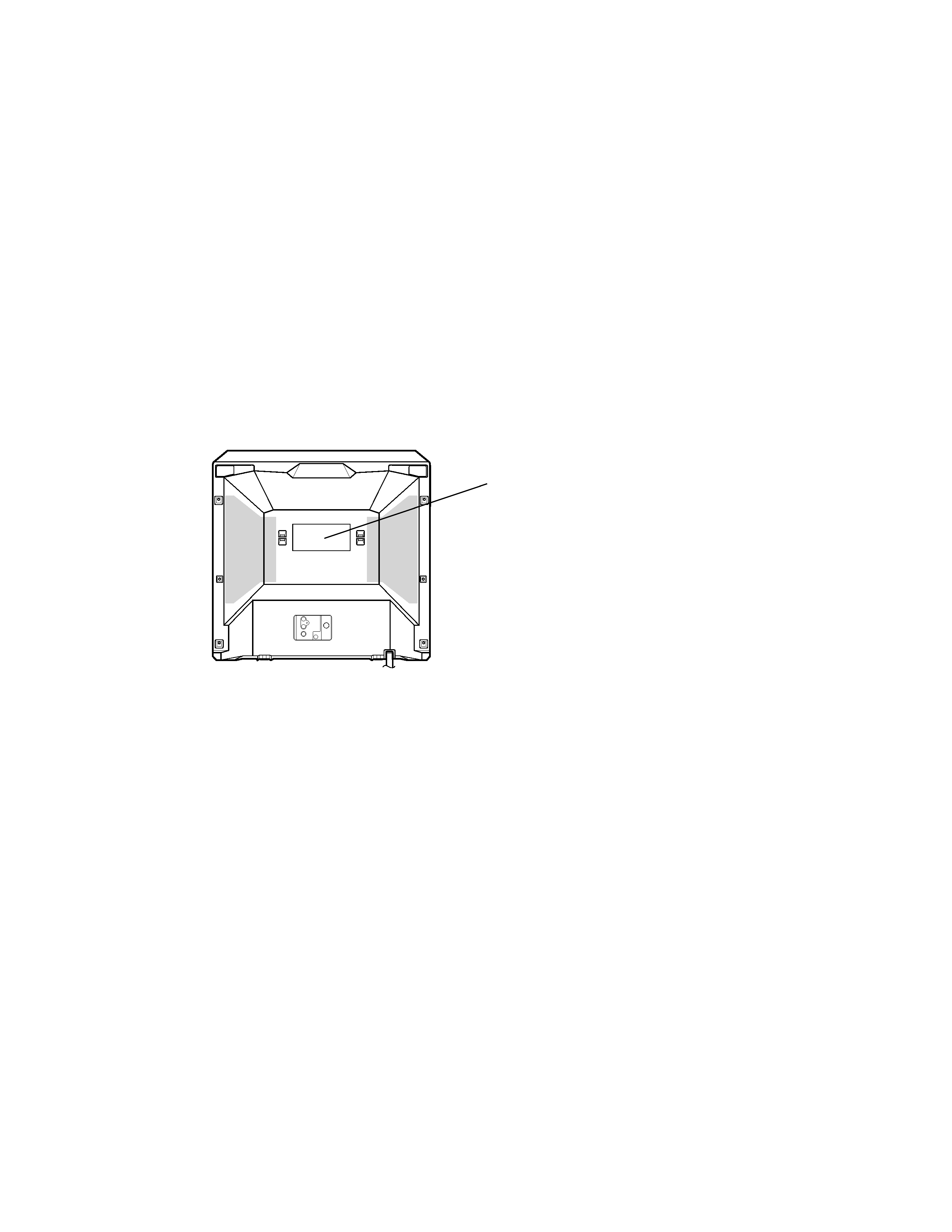
Location of the required Marking
The rating sheet and the safety caution are on the rear of the unit.
CERTIFICATION: COMPLIES WITH FDA
RADIATION PERFORMANCE STANDARDS,
21 CFR SUBCHAPTER J.
R
4
AV-20FD24
No. 52133
IMPORTANT SERVICE SAFETY INFORMATION
Operating the receiver outside of its cabinet or with its back
removed involves a shock hazard. Work on these models should
only be performed by those who are thoroughly familiar with
precautions necessary when working on high voltage equipment.
Exercise care when servicing this chassis with power applied. Many
B plus and high voltage RF terminals are exposed which, if care-
lessly contacted, can cause serious shock or result in damage to the
chassis.
Maintain interconnecting ground lead connections between chassis,
escutcheon, picture tube dag and tuner cluster when operating the
chassis.
These receivers have a "polarized" AC line cord. The AC plug is
designed to fit into standard AC outlets in one direction only. The
wide blade connects to the "ground side" and the narrow blade
connects to the "hot side" of the AC line. This assures that the TV
receiver is properly grounded to the house wiring. If an extension
cord must be used, make sure it is of the "polarized" type.
Since the chassis of this receiver is connected to one side of the AC
supply during operation, service should not be attempted by anyone
not familiar with the precautions necessary when working on these
types of equipment.
When it is necessary to make measurements or tests with AC power
applied to the receiver chassis, an Isolation Transformer must be
used as a safety precaution and to prevent possible damage to
transistors. The Isolation Transformer should be connected between
the TV line cord plug and the AC power outlet.
Certain HV failures can increase X-ray radiation.
Receivers should not be operated with HV levels exceeding the
specified rating for their chassis type. The maximum operating HV
specified for the chassis used in these receivers is 32kV±1.0kV at
zero beam current with a line voltage of 120V AC. Higher voltage
may also increase the possibility of failure in the HV supply.
It is important to maintain specified values of all components in the
horizontal and high voltage circuits and anywhere else in the
receiver that could cause a rise in high voltage, or operating supply
voltages. No changes should be made to the original design of the
receiver.
Components shown in the shaded areas on the schematic diagram
and/or identified by
! in the replacement parts list should be
replaced only with exact factory recommended replacement parts.
The use of unauthorized substitute parts may create shock, fire, X-
ray radiation, or other hazards.
To determine the presence of high voltage, use an accurate high
impedance HV meter connected between the second anode lead
and the CRT dag grounding device. When servicing the High
Voltage System, remove static charges from it by connecting a 10k
ohm resistor in series with an insulated wire (such as a test probe)
between the picture tube dag and 2nd anode lead (have AC line
cord disconnected from AC supply).
The picture tube used in this receiver employs integral implosion
protection. Replace with a tube of the same type number for
continued safety. Do not lift picture tube by the neck. Handle the
picture tube only when wearing shatterproof goggles and after
discharging the high voltage completely. Keep others without
shatterproof goggles away.
When removing springs or spring mounted parts from the tuner,
tuner cluster or chassis, shatterproof goggles must be worn. Keep
others without shatterproof goggles away.
Before returning the receiver to the user, perform the following
safety checks:
1. Inspect all lead dress to make certain that leads are not pinched
or that hardware is not lodged between the chassis and other
metal parts in the receiver.
2. Replace all protective devices such as nonmetallic control knobs,
insulating fishpapers, cabinet backs, adjustment and compart-
ment covers or shields, isolation resistor-capacitor networks,
mechanical insulators, etc.
3. To be sure that no shock hazard exists, a check for the presence
of leakage current should be made at each exposed metal part
having a return path to the chassis (antenna, cabinet metal,
screw heads, knobs and/or shafts, escutcheon, etc.) in the
following manner.
Plug the AC line cord directly into a 120V AC receptacle.
(Do not use an Isolation Transformer during these checks.) All
checks must be repeated with the AC line cord plug connection
reversed. (If necessary, a nonpolarized adapter plug must be used
only for the purpose of completing these checks.)
If available, measure current using an accurate leakage current
tester. Any reading of 0.35mA or more is excessive and indicates a
potential shock hazard which must be corrected before returning the
receiver to the owner.
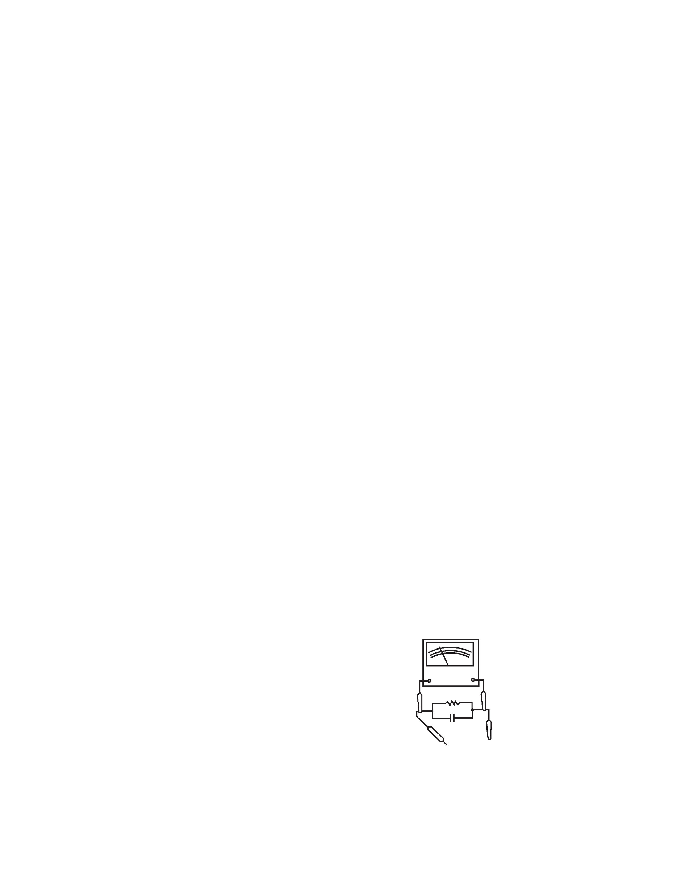
If a reliable leakage current tester is not available, this alternate
method of measurement should be used.
Using two clip leads, connect a 1500 ohm, 10 watt resistor paral-
leled by a 0.15µF capacitor in series with a known earth ground,
such as a water pipe or conduit and the metal part to be checked.
Use a VTVM or VOM with 1000 ohms per volt, or higher, sensitivity
to measure this AC voltage drop across the resistor. Any reading of
0.35 volt RMS or more is excessive and indicates a potential shock
hazard which must be corrected before returning the receiver to the
owner.
TO KNOWN
EARTH GROUND
AC SCALE
VT VM
1.5K OHMS
10W
15µF
TEST PROBE
TO EXPOSED
METAL PARTS
No. 52133
5
AV-20FD24
IMPORTANT SAFEGUARDS
1. READ INSTRUCTIONS
All the safety and operating instructions should be read before the unit is operated.
2. RETAIN INSTRUCTIONS
The safety and operating instructions should be retained for future reference.
3. HEED WARNINGS
All warnings on the unit and in the operating instructions should be adhered to.
4. FOLLOW INSTRUCTIONS
All operating and use instructions should be followed.
5. CLEANING
Unplug this unit from the wall outlet before cleaning. Do not use liquid cleaners or aerosol cleaners. Use a damp cloth for cleaning.
6. ATTACHMENTS
Do not use attachments not recommended by the unit's manufacturer as they may cause hazards.
7. WATER AND MOISTURE
Do not use this unit near water. For example, near a bathtub, washbowl, kitchen sink, or laundry tub, in a wet basement, or near a swimming
pool.
8
ACCESSORIES
Do not place this unit on an unstable cart, stand, tripod, bracket, or table. The unit may fall, causing
serious injury, and serious damage to the unit. Use only with a cart, stand, tripod, bracket, or table
recommended by the manufacturer.
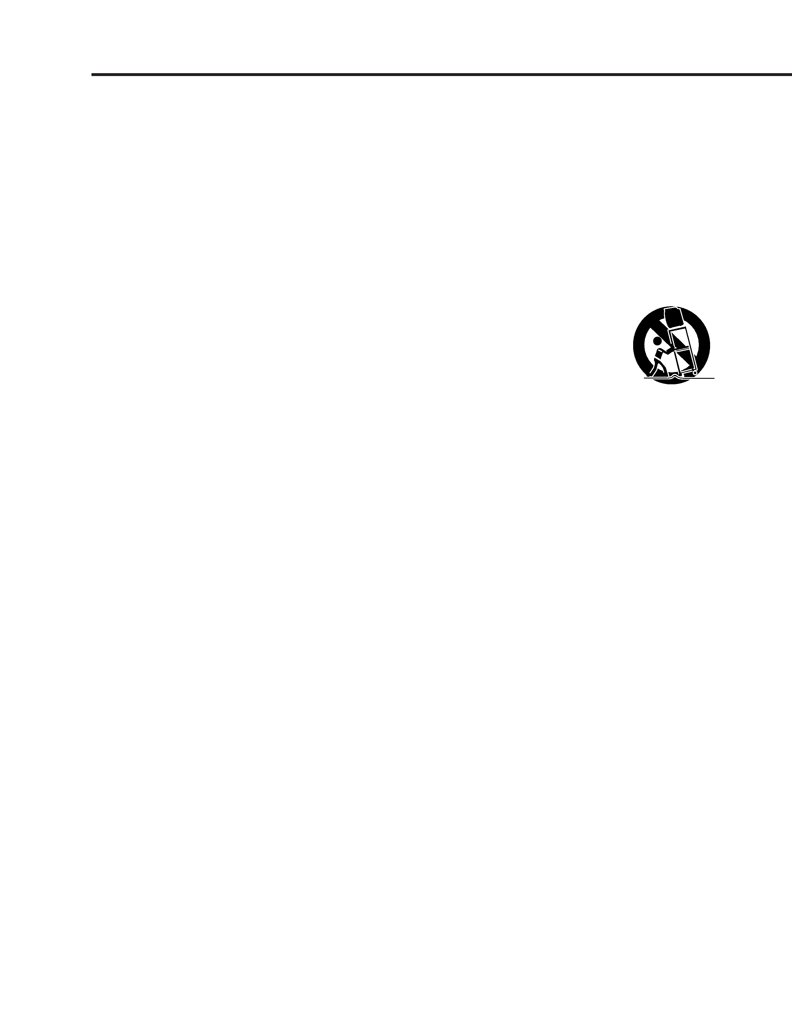
8A. An appliance and cart combination should be moved with care. Quick stops, excessive force, and
uneven surfaces may cause the appliance and cart combination to overturn.
9. VENTILATION
Slots and openings in the cabinet and in the back or bottom are provided for ventilation, to ensure reliable operation of the unit, and to
protect it from overheating. These openings must not be blocked or covered. The openings should never be blocked by placing the unit on a
bed, sofa, rug, or other similar surface. This unit should never be placed near or over a radiator or heat source. This unit should not be
placed in a built-in installation such as a bookcase or rack unless proper ventilation is provided or the manufacturer's instructions have been
adhered to.
10. POWER SOURCES
This unit should be operated only from the type of power source indicated on the rating plate. If you are not sure of the type of power supply
to your home, consult your appliance dealer or local power company. For units intended to operate from battery power, or other sources,
refer to the operating instructions.
11. GROUNDING OR POLARIZATION
This unit is equipped with a polarized alternating-current line plug (a plug having one blade wider than the other). This plug will fit into the
power outlet only one way. This is a safety feature. If you are unable to insert the plug fully into the outlet, try reversing the plug. If the plug
should still fail to fit, contact your electrician to replace your obsolete outlet. Do not defeat the safety purpose of the polarized plug. If your
unit is equipped with a 3-wire grounding-type plug, a plug having a third (grounding) pin, this plug will only fit into a grounding-type power
outlet. This too, is a safety feature. If you are unable to insert the plug into the outlet, contact your electrician to replace your obsolete outlet.
Do not defeat the safety purpose of the grounding-type plug.
12. POWER-CORD PROTECTION
Power-supply cords should be routed so that they are not likely to be walked on or pinched by items placed upon or against them, paying
particular attention to cords at plugs, convenience receptacles, and the point where they exit from the appliance.
13. LIGHTNING
To protect your unit from a lightning storm, or when it is left unattended and unused for long periods of time, unplug it from the wall outlet and
disconnect the antenna or cable system. This will prevent damage to the unit due to lightning and power line surges.
14. POWER LINES
An outside antenna system should not be located in the vicinity of overhead power lines or other electric light or power circuits, or where it
can fall into such power lines or circuits. When installing an outside antenna system, extreme care should be taken to keep from touching
such power lines or circuits, as contact with them might be fatal.
15. OVERLOADING
Do not overload wall outlets and extension cords, as this can result in a risk of fire or electric shock.
16. OBJECT AND LIQUID ENTRY
Do not push objects through any openings in this unit, as they may touch dangerous voltage points or short out parts that could result in fire
or electric shock. Never spill or spray any type of liquid into the unit.
17. OUTDOOR ANTENNA GROUNDING
If an outside antenna or cable system is connected to the unit, be sure the antenna or cable system is grounded so as to provide some
protection against voltage surges and built-up static charges. Section 810 of the National Electrical Code, ANSI/NFPA 70, provides informa-
tion with respect to proper grounding of the mast and supporting structure, grounding of the lead-in wire to an antenna discharge unit, size of
grounding conductors, location of antenna discharge unit, connection to grounding electrodes, and requirements for the grounding electrode.
18. SERVICING
Do not attempt to service this unit yourself as opening or removing covers may expose you to dangerous voltage or other hazards.
Refer all servicing to qualified service personnel.
PORTABLE CART WARNING
(symbol provided by RETAC)
S3126A