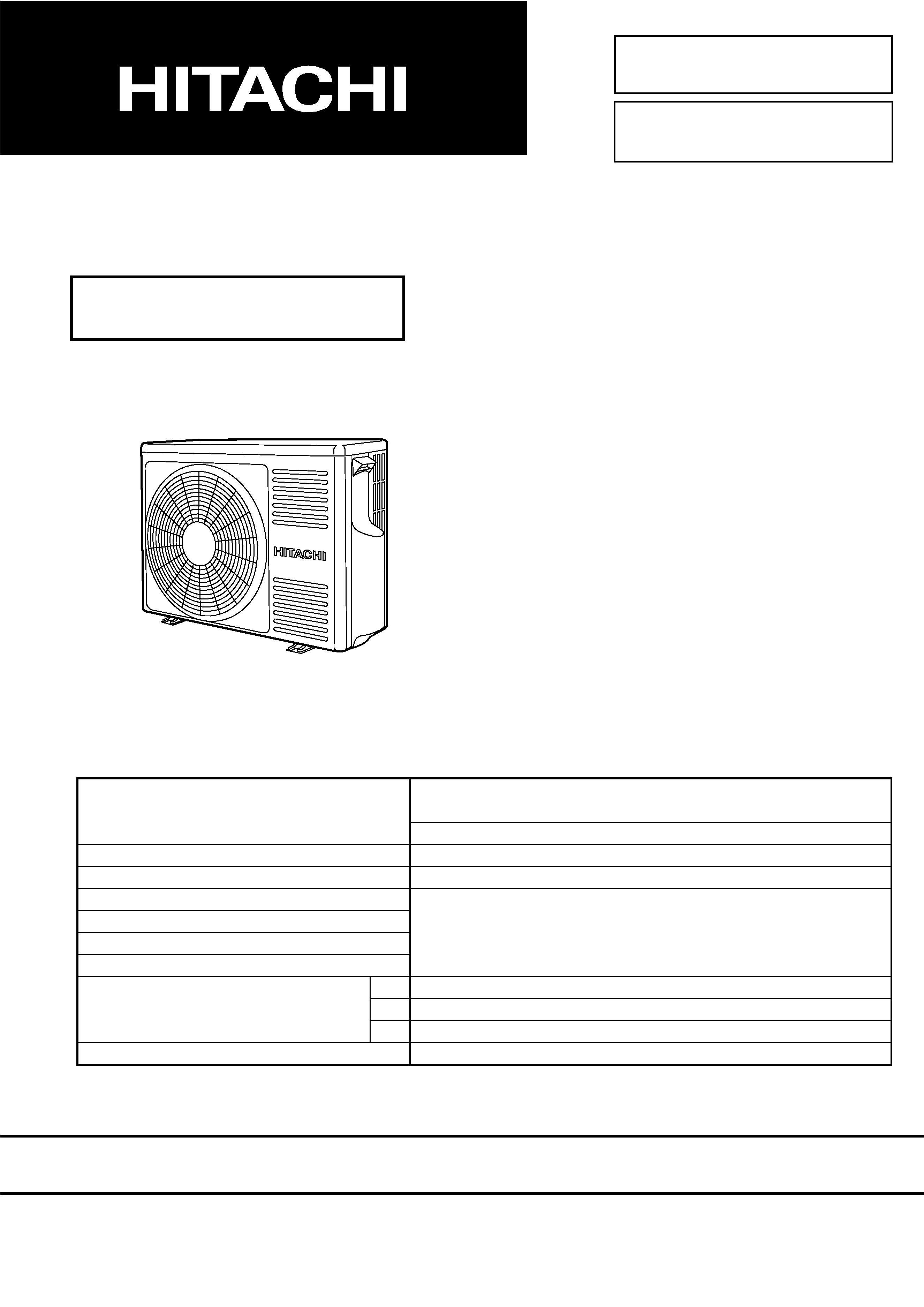
SM0758
RAM60QH4
SERVICE MANUAL
TECHNICAL INFORMATION
INFORMATIONS TECHNIQUES
REFER TO THE FOUNDATION MANUAL
REPORTEZ-VOUS AU MANUEL DE BASE
ROOM AIR CONDITIONER
SPECIFICATIONS AND PARTS ARE SUBJECT TO CHANGE FOR IMPROVEMENT
LES SPECIFICATIONS ET PIECES DETACHEES PEUVENT CHANGER POUR ETRE AMELIOREES.
FOR SERVICE PERSONNEL ONLY
RESERVE AU PERSONNEL
ROOM AIR CONDITIONER
OUTDOOR UNIT
SEPTEMBER 2003
Hitachi Home & Life Solutions, Inc.
After installation
Après installation
SPECIFICATIONS
CARACTERISTIQUES GENERALES
SPECIFICATIONS
9
CARACTERISTIQUES GENERALES
INSTALLATION
18
INSTALLATION
CONSTRUCTION AND DIMENSIONAL DIAGRAM
24
DIMENSIONS DES UNITÉS
REFRIGERATING CYCLE DIAGRAM
26
SCHÉMA DU CYCLE DE RÉFRIGÉRATION
MAIN PARTS COMPONENT
28
PRINCIPAUX COMPOSANTS
WIRING DIAGRAM
31
SCHÉMAS ÉLECTRIQUES
WIRING DIAGRAM OF THE PRINTED WIRING BOARD
35
SCHÉMA ÉLECTRIQUE DU CIRCUIT IMPRIMÉ
BLOCK DIAGRAM
38
ORGANIGRAMME DE CONTROLE
BASIC MODE
41
MODE DE BASE
DESCRIPTION OF MAIN CIRCUIT OPERATION
80
DESCRIPTION DES PRINCIPAUX CIRCUITS ÉLECTRIQUES
TROUBLE SHOOTING
130
DETECTION DES PANNES
DISASSEMBLY AND REASSEMBLY
160
DEMONTAGE ET REMONTAGE
HOT PIPE INSTALLATION WORK SHEET
165
FICHE DE TRAVAIL D'INSTALLATION DE TUYAU À
CIRCULATION HAUTE TEMPÉRATURE
PARTS LIST AND DIAGRAM
168
LISTE DES PIECES DE RECHANGE ET DIAGRAMME
CONTENTS
TABLE DES MATIERES
RAM60QH4
TYPE
TYPE
MODEL
MODÈLE
POWER SOURCE
PHASE/TENSION/FREQUENCE
TOTAL INPUT
PUISSANCE ABSORBEE TOTALE (W)
TOTAL AMPERES
AMPERES TOTAUX
(A)
COOLING CAPACITY REFRIGERATION CAPACITE
(kW)
HEATING CAPACITY CHAUFFAGE CAPACITE
(B.T.U.)
W
DIMENSIONS
DIMENSIONS
(mm)
H
D
NET WEIGHT
POIDS NET
(kg)
DC INVERTER DUAL SYSTEM MULTI
SYSTÈME DE DEUX ONDULEUR CC MULTI
OUTDOOR UNIT
UNITÉ EXTÉRIEURE
792 (+122)
600
299 (+46)
46
1ø, 230V, 50Hz
RAM60QH4
REFER TO THE SPECIFICATIONS PAGE 10.
REPORTEZ-VOUS AUX SPECIFICATIONS DE LA PAGE 11.
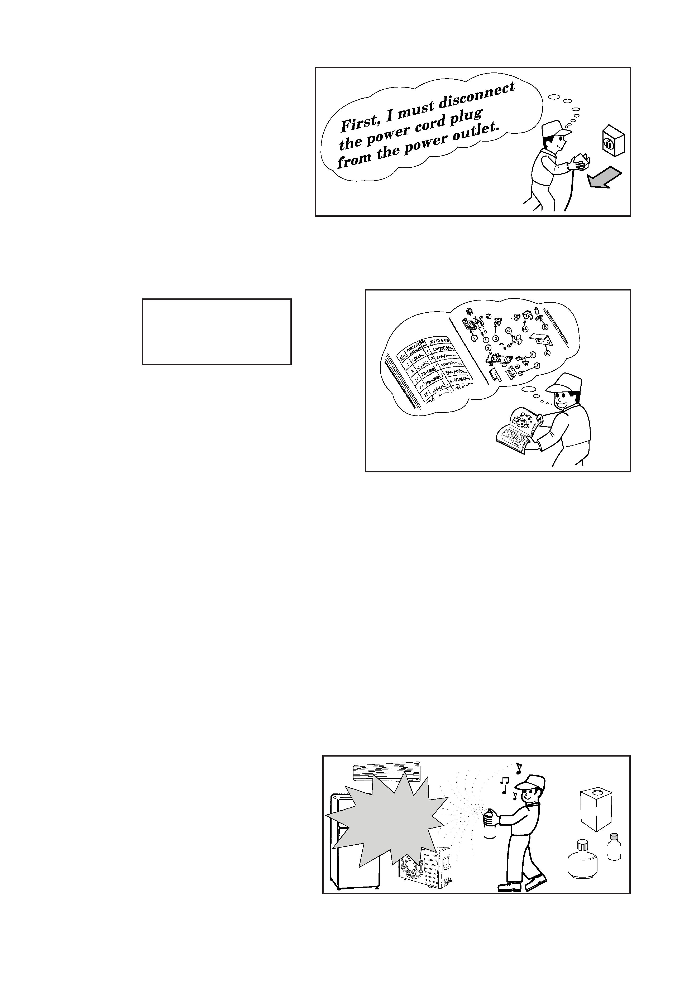
1. In order to disassemble and repair the
unit in question, be sure to disconnect the
power cord plug from the power outlet
before starting the work.
2. If it is necessary to replace any parts, they should be replaced with respective genuine parts for the unit,
and the replacement must be effected in correct manner according to the instructions in the Service
Manual of the unit.
3. After completion of repairs, the initial state should be
restored.
4. Lead wires should be connected and laid as in the
initial state.
5. Modification of the unit by the user himself should
absolutely be prohibited.
6. Tools and measuring instruments for use in repairs or inspection should be accurately calibrated in
advance.
7. In installing the unit having been repaired, be careful to prevent the occurrence of any accident such as
electrical shock, leak of current, or bodily injury due to the drop of any part.
8. To check the insulation of the unit, measure the insulation resistance between the power cord plug and
grounding terminal of the unit.
The insulation resistance should be 1M
or more as measured by a 500V DC megger.
9. The initial location of installation such as window, floor or the other should be checked for being safe
enough to support the repaired unit again.
If it is found not so strong and safe, the unit should be installed at the initial location after reinforced or
at a new location.
10. Any inflammable object must not be placed
about the location of installation.
11. Check the grounding to see whether it is
proper or not, and if it is found improper,
connect the grounding terminal to the earth.
Spray
gasoline
gasbombe
thinner
SAFETY DURING REPAIR WORK
If the contacts of electrical
parts are defective, replace
the electrical parts without
trying to repair them
1
2
3
4
5
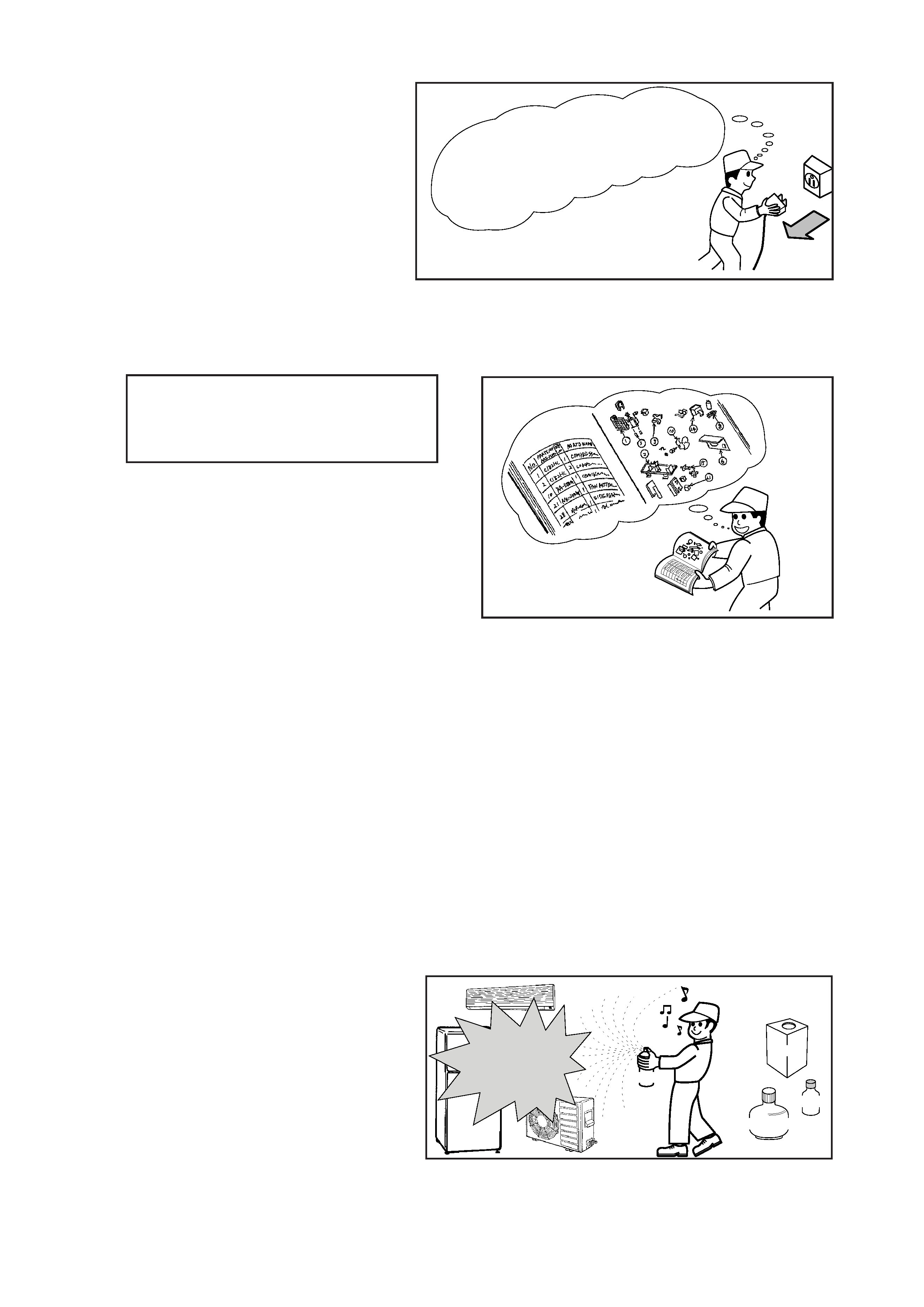
1.
Avant de procéder à une réparation, veillez
à couper l'alimentation électrique.
2.
Les pièces de rechange doivent être des pièces d'origine et le remplacement des pièces doit être réalisé
conformément aux instructions figurant dans le manuel d'entretien.
3. Après achèvement des réparations, les conditions
initiales doivent être rétablies.
4. Après toute intervention, le raccordement et le
cheminement des câbles électriques doivent être
rétablis comme à l'origine.
5. Toute modification au niveau de l'installation ne peut être effectuée que par une personne compétente.
Toute intervention ou modification par l'utilisateur lui-même est par conséquent à proscrire.
6. Les outils et les appareils de mesure qui doivent être employés pour effectuer l'entretien auront été
préalablement réglés ou étalonnés comme il convient.
7. Lors de l'installation d'une unité ayant subi une réparation, veillez à éviter tout accident dû à une décharge
électrique ou la chute d'un objet.
8. Pour vérifier l'isolement de l'appareillage, mesurer la résistance entre le cordon d'alimentation et la borne
de masse. Cette résistance doit au moins être égale à 1M
lorsque la mesure est effectuée avec un
mégohmmètre de 500V CC.
9. Avant la fixation de l'unité réparée, vérifiez que les fixations d'origine peuvent supporter l'appareil. Si ces
fixations vous paraissent défectueuses, renforcez-les si possible et dans le cas contraire, l'unité doit être
fixée à un autre endroit.
10. L'emplacement de l'installation doit être
éloignée de toute matière inflammable.
11. La mise à la masse doit être soigneusement
contrôlée; en cas de défaut, la borne de
masse doit être mise à la terre.
Il faut
d'abord
que
je coupe
I'alim
entation
électr
ique.
Aérosol
Essence
Dilunt
Bonbonne de gaz
PRECAUTIONS RELATIVES A LA SECURITE PENDANT LES REPARATIONS
Si vous constatez que les contacts d'un
composant électrique sont défectueux,
remplacez le composant et ne tentez pas
de réparer les contacts.
1
2
3
4
5
1
2
WORKING STANDARDS FOR PREVENTING BREAKAGE OF SEMICONDUCTORS
1. Scope
The standards provide for items to be generally observed in carrying and handling semiconductors in
relative manufactures during maintenance and handling thereof. (They apply the same to handling of
abnormal goods such as rejected goods being returned.)
2. Object parts
(1) Micro computer
(2) Integrated circuits (I.C.)
(3) Field effective transistor (F.E.T.)
(4) P.C. boards or the like to which the parts mentioned in (1) and (2) of this paragraph are equipped.
3. Items to be observed in handling
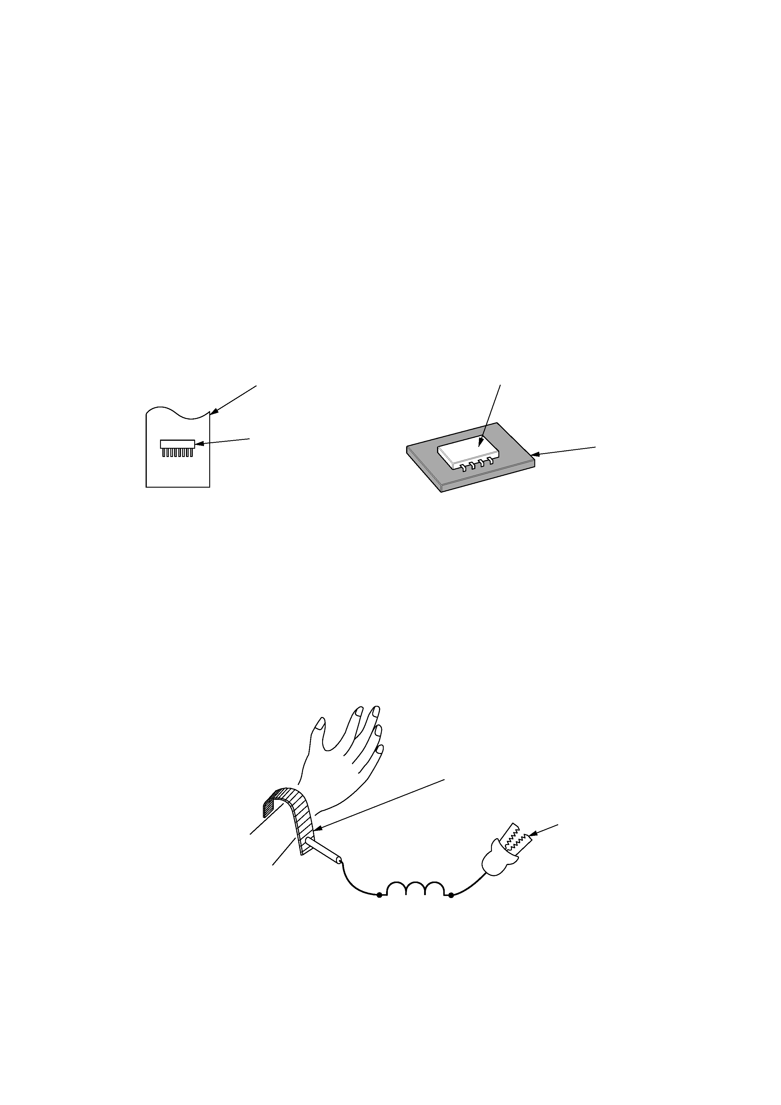
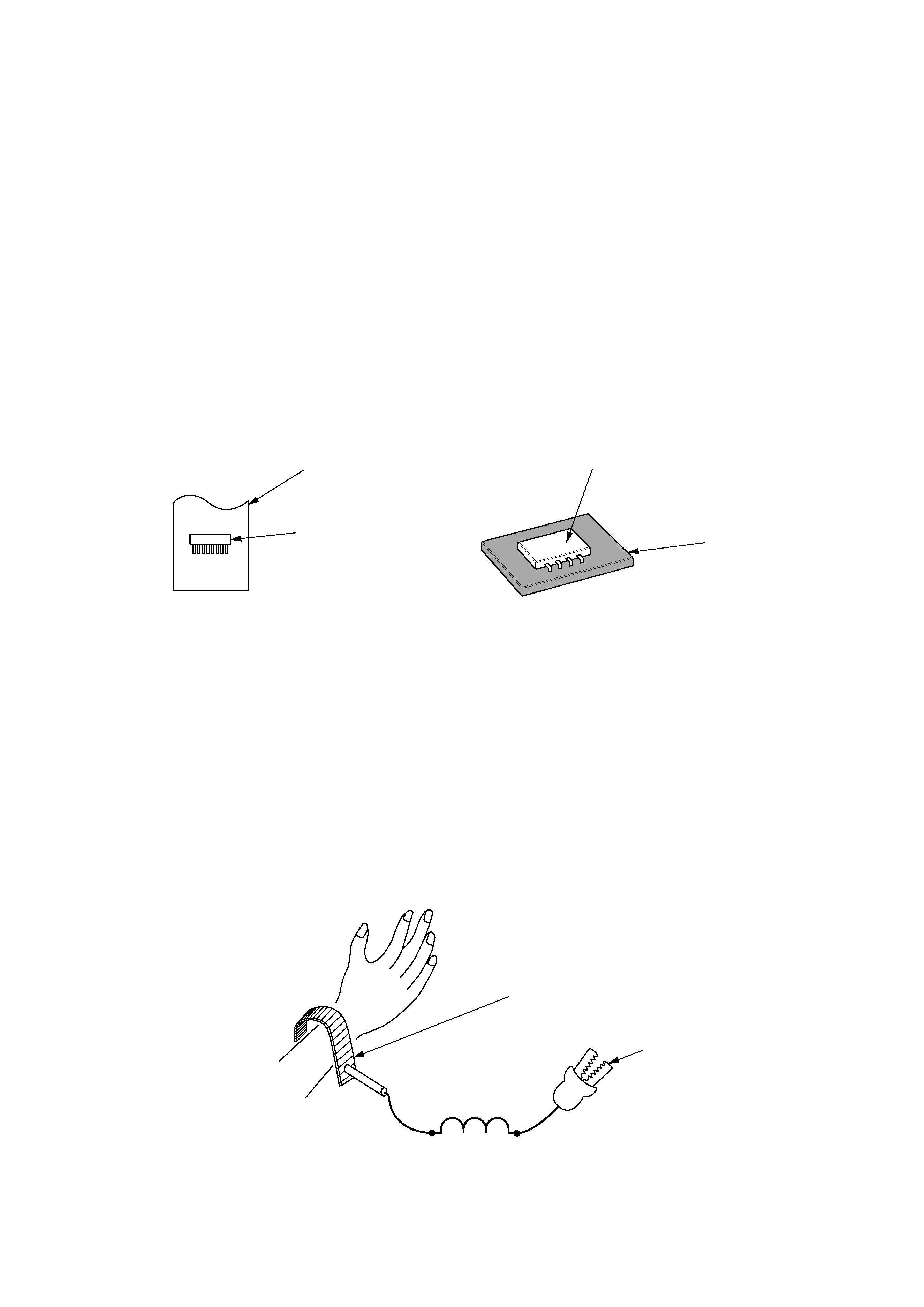
(1) Use a conductive container for carrying and storing of parts. (Even rejected goods should be handled in
the same way.)
(2) When any part is handled uncovered (in counting, packing and the like), the handling person must
always use himself as a body earth. (Make yourself a body earth by passing one M ohm earth
resistance through a ring or bracelet.)
(3) Be careful not to touch the parts with your clothing when you hold a part even if a body earth is
being taken.
(4) Be sure to place a part on a metal plate with grounding.
(5) Be careful not to fail to turn off power when you repair the printed circuit board.
At the same time,
try to repair the printed circuit board on a grounded metal plate.
HIT
ACH
I IC4
01T
H1 ,
188
UV
Fig. 1 Conductive container
A conductive polyvinyl bag
IC
IC
Conductive sponge
Fig. 2 Body earth
Body earth (Elimik conductive band)
Clip for connection with
a grounding wire
1M
3
PREVENTION DES DOMMAGES AUX SEMI-CONDUCTEURS
1. Champ d'application
Pour éviter d'endommager les semi-conducteurs utilisés dans les unités, lors de chaque intervention
d'entretien ou de réparation, vous devez observer des précautions spéciales. Les mêmes précautions
doivent être prises lors de la manipulation d'organes défectueux qui doivent être retournés en usine.
2. Pièces détachées de l'appareillage.
(1) Micro-ordinateur
(2) Circuits intégrés (C.I.)
(3) Transistor à effet de champ (T.E.C)
(4) Circuits imprimés sur lesquels se trouvent implantés les composants (1) et (2).
3. Précautions de manipulation
(1) Pour transporter ou stocker un semi-conducteur, placez-le dans un emballage conducteur. Procéder de
même avec un composant défectueux.
(2) Lorsque vous maniqulez des composants qui ne sont pas protégés (par exemple pour les compter ou
les emballer), vous devez veiller à ce que votre corps soit électriquement relié à la terre. Pour cela,
portez un bracelet conducteur. Reliez le bracelet à une résistance de 1M
et celle-ci à la terre par
l'intermédiaire d'un conducteur.
(3) Veillez en outre à ce que vos vêtements ne viennent jamais en contact avec le composant même si
votre corps est relié à la terre.
(4) Déposez le composant sur une surface métallique correctement mise à la terre.
(5) Sous aucun prétexte, n'omettez de couper l'alimentation avant de procéder à une réparation sur un
circuit imprimé.
Par ailleurs, l'intervention sur le circuit imprimé doit se faire alors que celui-ci repose
sur une surface métallique mise à la masse.
HIT
ACH
I IC4
01T
H1 ,
188
UV
Fig. 1 Emballage conducteur
Sac en polyvinyle
conducteur
C.I.
C.I.
Eponge
conductrice
Fig. 2 Mise à la terre du corps
Bracelet de mise à la terre du corps
(Bande conductrice Elimik)
Pince de connexion avec
fil de mise à la terre
1M
