SERVICE MANUAL
ELECTRONIC CASH REGISTER
(without price)
JANUARY 1997
TK-800 (EX-547)
Printer Model : MD-910
MC-Service

CONTENTS
Page
1. SPECIFICATIONS ................................................................................................ 1
2. INITIALIZE (MAC) OPERATION .......................................................................... 2
3. F-INIT (FMAC) OPERATION ................................................................................ 2
4. BLOCK DIAGRAM
4-1. PCB connection ......................................................................................... 3
4-2. Block diagram (circuit) .............................................................................. 4
5. CIRCUIT EXPLANATION
5-1. Power supply circuit .................................................................................. 5
5-2. CPU (uPD78052GC-093-3B9) .................................................................... 6
5-3. Display controller (uPD16312GB-3B4) ..................................................... 8
5-4. Initialize IC (Reset circuit) ......................................................................... 9
5-5. Power down detection circuit (PWD) ....................................................... 9
5-6. Address latch circuit ................................................................................. 9
5-7. RAM / ROM bank selection circuit .......................................................... 10
5-8. To expand the memory capacity ............................................................ 11
5-9. Data communication between CPU and EEPROM ................................ 12
5-10. Head drive circuit for printer ................................................................... 14
5-11. VPP sensor circuit ................................................................................... 15
5-12. Power supply circuit for display ............................................................. 15
6. DIAGNOSTIC
6-1. To start the diagnostic program ............................................................. 16
6-2. Check item ................................................................................................ 16
6-3. Operation of each test ............................................................................. 16
6-4. To exit the diagnostic test ....................................................................... 22
7. ERROR CODE
7-1. Operation error code ............................................................................... 23
7-2. System lock code..................................................................................... 24
8. IC DATA
1.
TC74HC00AP ............................................................................................ 25
2.
TC74HC08AP ............................................................................................ 25
3.
TC74HC138 ............................................................................................... 25
4.
TC74HC367AP .......................................................................................... 26
5.
TL431CLPB ............................................................................................... 26
6.
TC74HC373AP .......................................................................................... 26
7.
S-80745 / S-80719 ..................................................................................... 27
8.
MAX232 ..................................................................................................... 27
9. PCB LAYOUT ..................................................................................................... 28
10. CIRCUIT DIAGRAMS ......................................................................................... 29
11. PARTS LIST ....................................................................................................... 45

-- 1 --
1. SPECIFICATIONS
Power consumption
120 V
220 V
230 V
240 V
In operation
Max.
0.28 A
0.17 A
0.16 A
0.15 A
Stand by
0.14 A
0.09 A
0.08 A
0.07 A
Mode SW OFF
Max.
0.12 A
0.08 A
0.07 A
0.06 A
Memory protection
Backup battery
Vanadium Lithium secondary battery
VL3032/1F2
Backup period
90 days (25
°C)
Battery life
5 years (25
°C)
Recharge time
48 hours
Memory capacity
SFD 32 KB
CXK58257AP-70/10L
Max 128 KB (with option: RAM 530)
Clock and calender
Accuracy
Within
±30 sec. per month (25 °C)
Auto calender
Effective until 2099 A.D.
Environment
Operating temperature
0
°C~ 40 °C
Operating humidity
10 % ~ 90 %
Storage temperature
-25
°C~ 65 °C
Storage humidity
10 % ~ 95 %
Printer
Model
MD-910-SSC
Print method
Dot matrix printing
Print digits
24 digits
MCBF
1,500,000 lines
Ink cassette
Life
250,000 characters
Roll paper
Type
Fine-quality paper or Pressure-sensitive copy paper
Size
57.5
±0.5 mm
Roll diameter
83 mm or less
CAUTION
Danger of explosion if battery is incorrectly replaced.
Replace only with the same or equivalent type
recommended by the manufacturer.
Dispose of used batteries according
to the manufacture's instructions.
VORSICHT !
Explosionsgefahr bei unsachgemäßem Austausch der Batterie.
Ersatz nur durch denselben oder einen vom
Hersteller empfohlenen gleichwertigen Typ.
Entsorgung gebrauchter Batterien nach
Angaben des Herstellers.
ADVARSEL !
Lithiumbatteri - Eksplosionsfare ved fejlagtig hándtering.
Udskiftning má kun ske med batteri
af samme fabrikat og type.
Levér det brugte batteri tilbage til leverandØren.

-- 2 --
2. INITIALIZE (MAC) OPERATION
INIT A: All memory clear
1. Set the mode switch to "OFF" position.
2. Pressing the "FEED" button and turn the mode switch to "PRG" position.
3. Release the "FEED" button.
4. Input the MAC CODE D1 (1 digit).
5. Press "#2" key.
6. Initialize operation is executed.
MAC CODE D1: 0: Detailed check tracking
2: Total check tracking
INIT B: Load the program from EEPROM
1. Set the mode switch to "OFF" position.
2. Pressing the "FEED" button and turn the mode switch to "PRG" position.
3. Release the "FEED" button.
4. Input t "0" "0" by numeral key.
5. Press "#2" key.
6. Initialize operation is executed.
3. F-INIT (FMAC) OPERATION
1. Set the mode switch to "OFF" position.
2. Pressing the "FEED" button and turn the mode switch to "PRG" position.
3. Release the "FEED" button.
4. Press "#2" key.
Note: The location of "#2" keys, see "HARD KEY CODE TABLE" on page 16.
-- 3 --
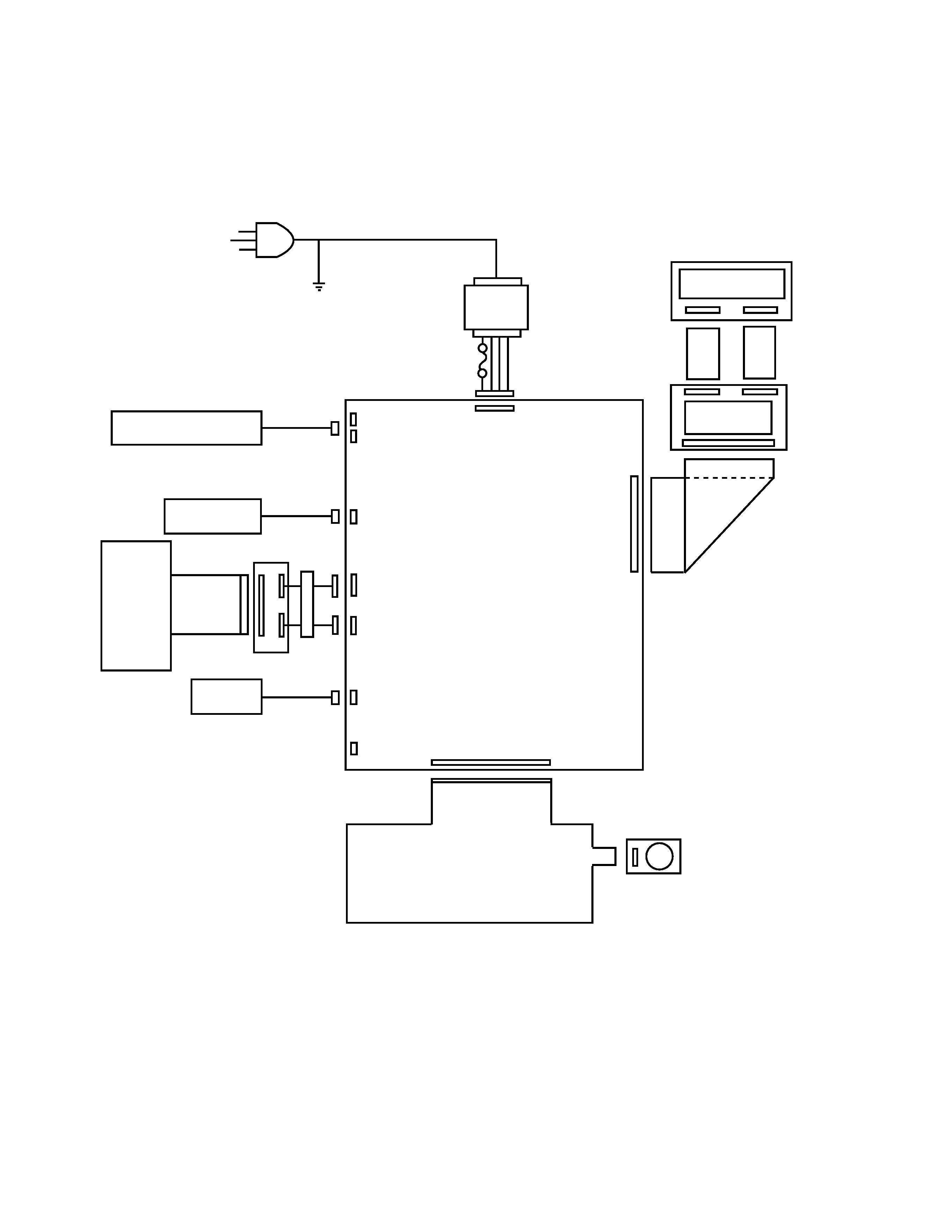
FPC
Mode SW
E266-E3-1
CN3
24P
Main Display
(SH101MA)
E278-E2-1
12P
10P
Rear Display
(SH1019A)
E278-E2-2
4P
Fuse
Transformer
3P
CN7
CN6
CN4
2P
17P
CN13
CN14
3P
CN2
(RS232C)
CN17
CN16
27P
9P
Vanadium Lithium Battery
VL3032
Winder
Motor
Printer
(MD910SSC)
Drawer
E247-CNB
CORE
2 turn
10P
7P
E247-1
4. BLOCK DIAGRAM
4-1. PCB connection
MC-Service