ELECTRONIC KEYBOARD
(with price)
CTK-630
CONTENTS
Page
Specifications ................................................................................................................................... 2
Block Diagram .................................................................................................................................. 3
Circuit Description ............................................................................................................................ 4
Troubleshooting ............................................................................................................................. 10
Major Waveforms ........................................................................................................................... 11
Printed Circuit Boards .................................................................................................................... 12
Schematic Diagrams ...................................................................................................................... 13
Exploded View ............................................................................................................................... 16
Parts List ........................................................................................................................................ 17

-- 2 --
ELECTRICAL
Nominal
Limit
Current drain with 9 V DC:
No sound output
220 mA
220 mA
± 30 %
Maximum volume
900 mA
900 mA
± 30 %
with white keys C4 to G5 pressed in Recorder tone
Volume: maximum, Touch response: maximum
Layer: On, Reberv: Off
Phone output level (Vrms with 8
load each channel):
with key C4 pressed in Recorder tone
125 mV
125 mV
± 30 %
Sound pressure (at 10 cm away from speaker):
with key A3 pressed in Recorder tone
98 dB
98 dB
± 10 dB
Minimum operating voltage:
5.8 V
6.0 V
SPECIFICATIONS
GENERAL
Number of keys:
61
Polyphonic:
24-note
Preset tones:
100, Tone expander: Layer On/Off, Split On/Off
Keyboard controls:
Touch response: On/Off, Key transpose: Range from F# to F by
a semitone increment, Pitch bend: 12 steps up and down (a seminote at
muximum)
Auto-rhythms:
100, Tempo control: 40 to 255
Auto-accompaniment:
Mode: CASIO Chord/Fingered/Full-Range Chord 1/
Full-Range Chord 2
Controller: Intro/Fill-In, Synchro/Ending, Normal/Variation
Easy presets:
50, including -- Free Session (Chord): 30, Free Session (Song): 10,
Melody Composition: 10
Reverb effects:
Hall/Stage/Room
Musical pads:
8
Pad variations:
50, including -- Pops: 10, Rock: 10, Jazz/Fusion: 10, Dance/Funk: 10
European: 2, Latin/Various: 5, Drums/Percussion: 5
Song memory:
3, Real-time recording, Memory capacity: Approx. 1200 notes in total
Demo tunes:
3, including -- A Night has 9000 Bars (arranged and programmed by
Thomas Hirsch), Wanting This (Edward Alstrom), Supersonic Remorse
(Edward Alstrom)
Demo tune program:
Repeat/Skip
Tuning control:
440Hz
± 50 cents
Built-in speakers:
12 cm dia. 2 W input rating: 2 pcs.
MIDI:
16 multi-channel reception
Terminals:
Phone Jack [Output impedance: 90
, Output voltage: 4.6 V(rms)
MAX], Sustain Jack, MIDI Jacks (IN, OUT), AC Adapter Jack (9 V)
Auto power off:
Approximately 6 minutes after the last operation
Power source:
2-way AC or DC source
AC: AC adapter
DC: 6 D size dry batteries
Power consumption:
7.7 W
Dimensions (HWD):
104 x 931 x 353 mm (4-1/16 x 36-5/8 x 13-7/8 inches)
Weight:
4.7 kg (10.4 lbs) including batteries
-- 3 --
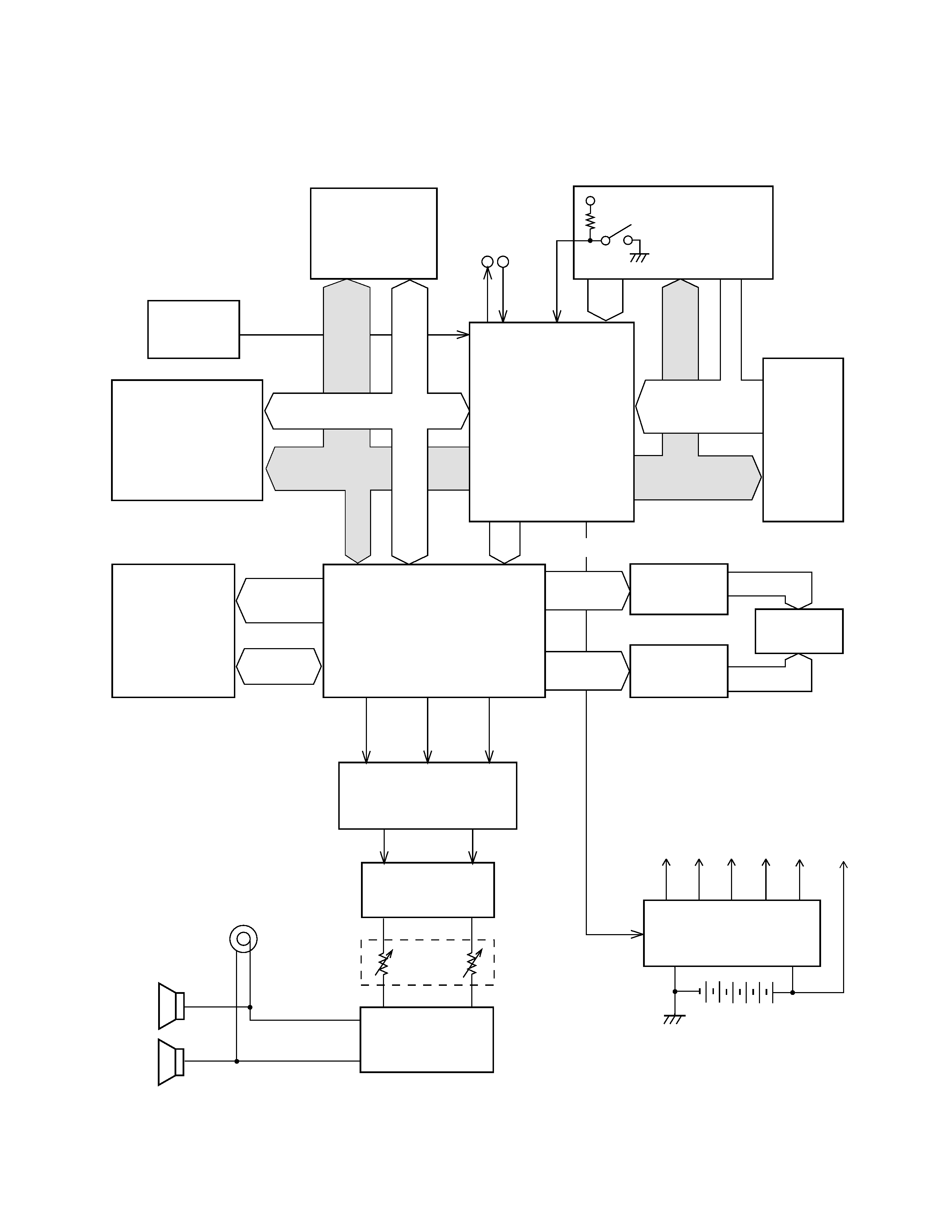
BLOCK DIAGRAM
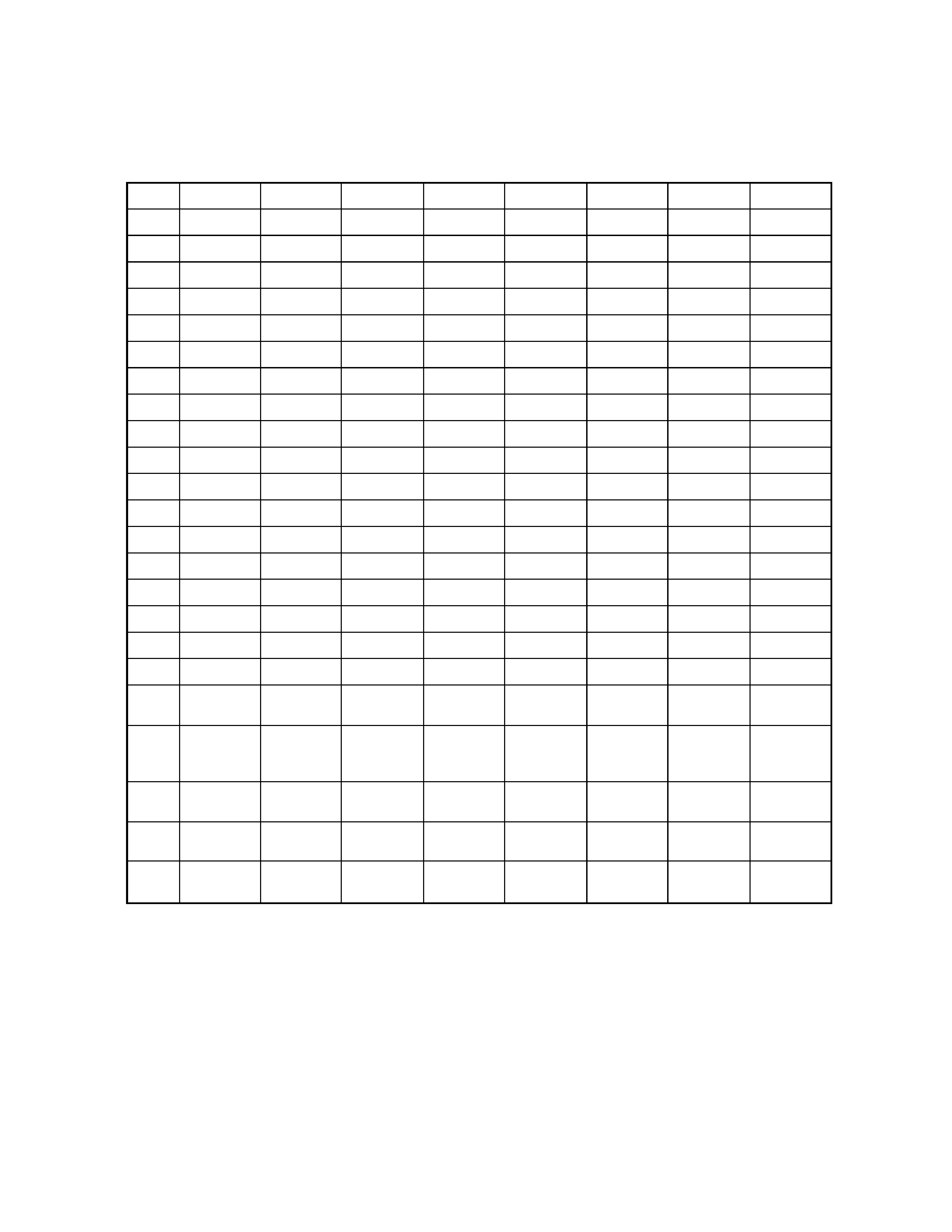
KC0 ~ KC7
FI0 ~ FI10
SI0 ~ SI19
Working Storage
RAM (64K-bit)
LSI103
SRM2264LM90
MIDI
EA0 ~
EA12
EIO0 ~
EIO7
Sound Source ROM
(16M-bit)
LSI104
MX23C1610MC-
12CA20
LRCK
SO
BCK
D/A Converter
IC102
UPD6379GR
Filter
Q108, Q109
Q119, Q120
Main
Volume
Power Amplifier
IC101
LA4598
LED driver
IC103
BA612
Keyboard
MA0 ~ MA19
Power Supply Circuit
Q101 ~ Q106
D101, D103, D104
VCC
AVDD
VDD
LVDD
DVDD
VC
APO
Effect RAM
(64K-bit)
LSI102
SRM2264LM90
MD0
~
MD7
Speakers
Output
MA0
~
MA12
MA0, MA1
LEDs /
7Seg. LED
LED driver
Q110 ~ Q117
La ~ Lg, Lp
IN
OUT
Reset IC
IC105
RE5VA35AA
RESET
LC0 ~ LC4
Buttons
VDD
Power Switch
PA0 ~ PA7
PB0 ~ PB4
CPU
LSI105
UPD912GF-3BA
BCK, SO, LRCK
DSP
LSI101
HG51B227FB
FI8 ~ FI10, SI8
KI0 ~ KI2
MD0 ~ MD15
-- 4 --
KC0
KC1
KC2
KC3
KC4
KC5
KC6
KC7
FI0
C2 (1)
C#2 (1)
D2 (1)
D#2 (1)
E2 (1)
F2 (1)
F#2 (1)
G2 (1)
SI0
C2 (2)
C#2 (2)
D2 (2)
D#2 (2)
E2 (2)
F2 (2)
F#2 (2)
G2 (2)
FI1
G#2 (1)
A2 (1)
A#2 (1)
B2 (1)
C3 (1)
C#3 (1)
D3 (1)
D#3 (1)
SI1
G#2 (2)
A2 (2)
A#2 (2)
B2 (2)
C3 (2)
C#3 (2)
D3 (2)
D#3 (2)
FI2
E3 (1)
F3 (1)
F#3 (1)
G3 (1)
G#3 (1)
A3 (1)
A#3 (1)
B3 (1)
SI2
E3 (2)
F3 (2)
F#3 (2)
G3 (2)
G#3 (2)
A3 (2)
A#3 (2)
B3 (2)
FI3
C4 (1)
C#4 (1)
D4 (1)
D#4 (1)
E4 (1)
F4 (1)
F#4 (1)
G4 (1)
SI3
C4 (2)
C#4 (2)
D4 (2)
D#4 (2)
E4 (2)
F4 (2)
F#4 (2)
G4 (2)
FI4
G#4 (1)
A4 (1)
A#4 (1)
B4 (1)
C5 (1)
C#5 (1)
D5 (1)
D#5 (1)
SI4
G#4 (2)
A4 (2)
A#4 (2)
B4 (2)
C5 (2)
C#5 (2)
D5 (2)
D#5 (2)
FI5
E5 (1)
F5 (1)
F#5 (1)
G5 (1)
G#5 (1)
A5 (1)
A#5 (1)
B5 (1)
SI5
E5 (2)
F5 (2)
F#5 (2)
G5 (2)
G#5 (2)
A5 (2)
A#5 (2)
B5 (2)
FI6
C6 (1)
C#6 (1)
D6 (1)
D#6 (1)
E6 (1)
F6 (1)
F#6 (1)
G6 (1)
SI6
C6 (2)
C#6 (2)
D6 (2)
D#6 (2)
E6 (2)
F6 (2)
F#6 (2)
G6 (2)
FI7
G#6 (1)
A6 (1)
A#6 (1)
B6 (1)
C7 (1)
SI7
G#6 (2)
A6 (2)
A#6 (2)
B6 (2)
C7 (2)
FI8
Pad A (1)
Pad B (1)
Pad C (1)
Pad D (1) Pad E (1)
Pad F (1)
Pad G (1)
Pad H (1)
SI8
Pad A (2)
Pad B (2)
Pad C (2)
Pad D (2) Pad E (2)
Pad F (2)
Pad G (2)
Pad H (2)
FI9
Intro/
Fill-In
Synchro/
Ending
Start/
Stop
FI10
Bend
Up
Bend
Down
Normal/
Variation
Tempo
Up
Tempo
Down
Accomp.
Volume
Up
Accomp.
Volume
Down
KI0
Mode
Reverb
0
1
4
7
Layer
Split
KI1
Rhythm
Tone
2
5
8
Transpose
Tune/MIDI
Demo
KI2
Easy
Preset
Pad
+
3
6
9
Memory
Touch
Response
CIRCUIT DESCRIPTION
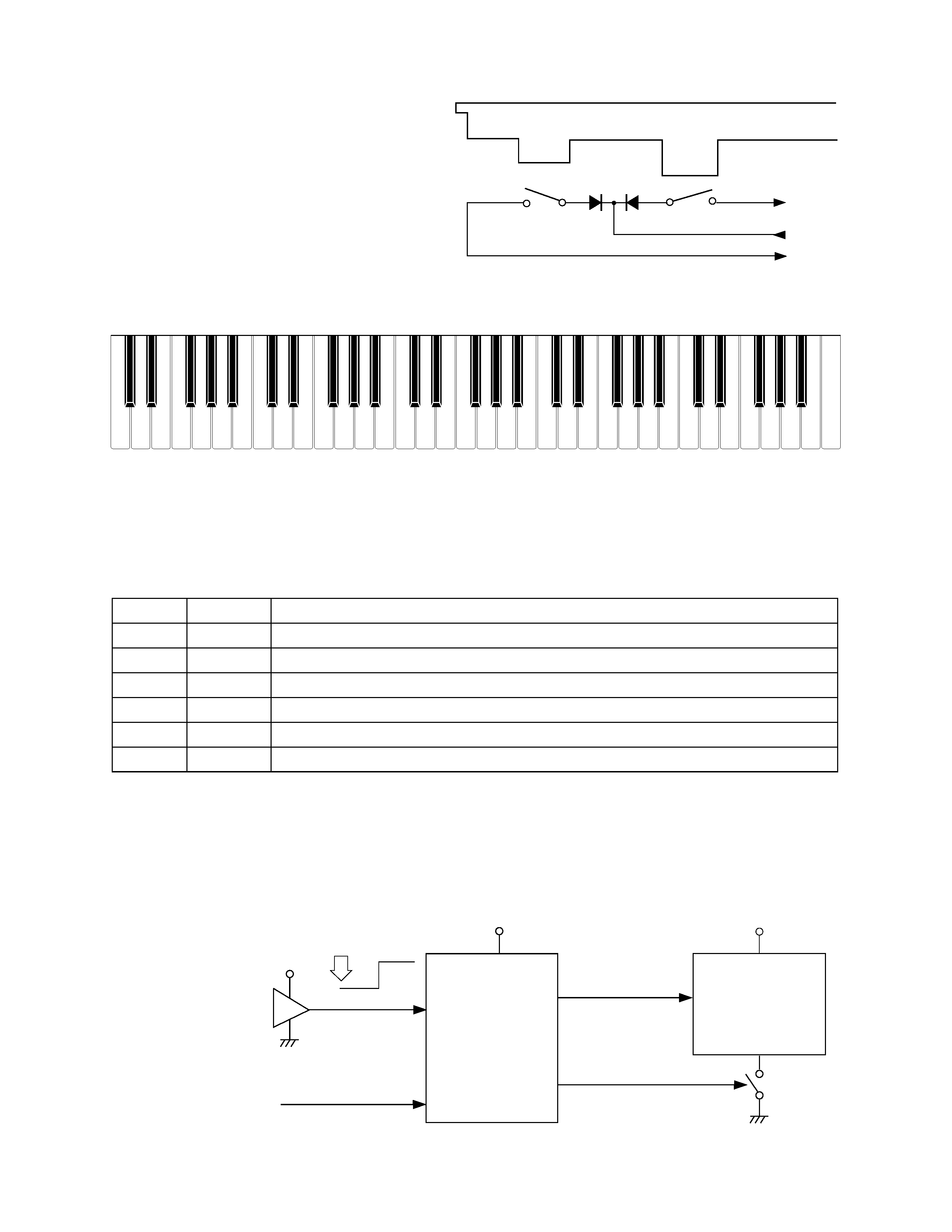
KEY MATRIX
-- 5 --
Key
Second contact (2)
First contact (1)
FI
KC
SI
Reset IC
IC105
RE5VA35AA
DSP
LSI101
HG51B227FB
VDD
Reset signal
VDD
Battery set
RESET
VDD
POWER
From power switch
NMI
APO
PLE
CPU
LSI105
UPD912GF-3BA
SCKO
Note: Each key has two contacts,
the first conatct (1) and second contact (2).
POWER SUPPLY CIRCUIT
The power supply circuit generates six voltages as shown in the following table. VDD voltage is always
generated. The others are controlled by APO signal from the CPU.
NOMENCLATURE OF KEYS
RESET CIRCUIT
When batteries are set or an AC adapter is connected, the reset IC provides a low pulse to the CPU. The
CPU then initializes its internal circuit, and clears the working storage RAM.
When the power switch is pressed, the CPU receives a low pulse of POWER signal. The CPU sends
APO signal to supply ground source for the DSP, also sends a reset signal to the DSP.
Name
Voltage
For operation of
VDD
+5 V
CPU, Reset IC, DSP, Sound source ROM, Working storage RAM, Effect RAM
DVDD
+5 V
Power jack, Sustain jack, MIDI jack
AVDD
+5V
DAC, Filter
LVDD
+4.5 V
LED Driver
VCC
+9 V
Power amplifier, Pilot lamp
VC
+9 V
Power amplifier
F#3 G#3 A#3
C#4 D#4
F#4 G#4 A#4
C#5 D#5
F#5 G#5 A#5
F3
G3
A3
B3
C4
D4
E4
F4
G4
A4
B4
C5
D5
E5
F5
G5
A5
B5
C6
D#3
C2
D2
E2
F2
G2
A2
B2
C3
D3
E3
B6
A6
G6
F6
E6
D6
C7
C#3
A#2
G#2
F#2
D#2
C#2
A#6
G#6
F#6
D#6
C#6