SERVICE MANUAL
DA
TA
CXLMS5
XRMS5
RCBAT01
SYSTEM
CD
CASSEIVER
REMOTE
CONTROLLER
COMPACT DISC
STEREO SYSTEM
BASIC CD MECHANISM : AZG-X A1NM
XR-MS5 U
S/M Code No. 09-012-441-8R1
SPEAKER
SXLMS5
This Service Manual is the Revision Publishing and replaces Simple Manual
(S/M Code No. 09-011-441-8T1).
REVISION

2
TABLE OF CONTENTS
SPECIFICATIONS ...............................................................................................................................................................3
PROTECTION OF EYES FROM LASER BEAM DURING SERVICING ........................................................................4
PRECAUTION TO REPLACE OPTICAL BLOCK .............................................................................................................4
DISASSEMBLY INSTRUCTIONS 1............................................................................................................................5 ~ 7
DISASSEMBLY INSTRUCTIONS 2..........................................................................................................................8 ~ 13
ELECTRICAL MAIN PARTS LIST ........................................................................................................................... 14 ~ 17
CHIP RESISTOR PART CODE .......................................................................................................................................17
TRANSISTOR ILLUSTRATION.........................................................................................................................................18
WIRING 1 (MAIN / HP J) .............................................................................................................................................19
SCHEMATIC DIAGRAM 1 (MAIN : 1 / 2 / HP J) .........................................................................................................20
SCHEMATIC DIAGRAM 2 (MAIN : 2 / 2 <MICON SECTION>) ....................................................................................21
WIRING 2 (FRONT / AMP) ............................................................................................................................................22
SCHEMATIC DIAGRAM 3 (FRONT) .............................................................................................................................23
SCHEMATIC DIAGRAM 4 (AMP) ..................................................................................................................................24
WIRING 3 (TUNER) .......................................................................................................................................................25
SCHEMATIC DIAGRAM 5 (TUNER) .............................................................................................................................26
WIRING 4 (AC 2M / PT MAIN) .....................................................................................................................................27
SCHEMATIC DIAGRAM 6 (AC 2M / PT MAIN) ...........................................................................................................28
WIRING 5 (CD) <1 / 2> .................................................................................................................................................29
WIRING 5 (CD) <2 / 2> .................................................................................................................................................30
SCHEMATIC DIAGRAM 7 (CD) ....................................................................................................................................31
FL (9 ST 24GONK) GRID ASSIGNMENT / ANODE CONNECTION / PIN CONNECTION ............................... 32 ~ 35
IC BLOCK DIAGRAM ............................................................................................................................................... 36 ~ 38
IC DESCRIPTION ..................................................................................................................................................... 39 ~ 45
ADJUSTMENT (TUNER / MICON) ....................................................................................................................................46
CD TEST MODE ...................................................................................................................................................... 47 ~ 48
MECHANICAL PARTS ARRANGEMENT ................................................................................................................ 49 ~ 53
MECHANICAL PARTS LIST 1 / 1 ....................................................................................................................................54
COLOR NAME TABLE .....................................................................................................................................................54
CD MECHANISM EXPLODED VIEW 1 / 1 .....................................................................................................................55
CD MECHANISM PARTS LIST 1 / 1 ..............................................................................................................................56
GENERAL SPEAKER DISASSEMBLY INSTRUCTIONS (FOR REFERENCE) ............................................................57
SPEAKER PARTS LIST (SX LMS5) <YJBN> ...............................................................................................................58
ACCESSORIES / PACKAGE LIST ....................................................................................................................................58

3
SPECIFICATIONS
MAIN UNIT
TUNER
FM tuning range
87.5 MHz to 108 MHz
FM usable sensitivity (IHF) 13.2 dBf
FM antenna terminals
75 ohms (unbalanced)
AM tuning range
530 kHz to 1710 kHz (10 kHz step)
531 kHz to 1602 kHz (9 kHz step)
AM usable sensitivity
350 µV/m
AM antenna
Loop antenna
AMPLIFIER
Power output
12 W + 12 W (50 Hz 20 kHz,
THD less than 1 %, 6 ohms)
15 W + 15 W (1 kHz,
THD less than 10 %, 6 ohms)
Total harmonic distortion
0.05 % (6 W, 1 kHz, 6 ohms, DIN
AUDIO)
Input
VIDEO/AUX: 600 mV
Outputs
SPEAKERS: 6 ohms or more
PHONES: 16 ohms or more
SUPER WOOFER 0.85 V
DIGITAL OUT (OPTICAL) jack
LINE OUT jack
CD PLAYER
Laser
Semiconductor laser (l = 780 nm)
D/A converter
1 bit dual
Signal-to-noise ratio
85 dB (1 kHz, 0 dB)
Harmonic distortion
0.08 % (1 kHz, 0 dB)
Wow and flutter
unmeasurable
Design and specifications are subject to change without notice.
The word "BBE" and the "BBE symbol" are trademarks of BBE
Sound, Inc.
Under license from BBE Sound,Inc.
GENERAL
Power requirements
120 V AC, 60 Hz
Power consumption
45 W
Power consumption in standby mode
With ECO mode on: 0.7 W
With ECO mode off: 13 W
Dimensions (W x H x D)
100.0 x 205.0 x 292.5 mm
(4 x 81/8 x 115/8 in.)
Weight
3.5 kg (7 lbs 12 oz.)
SPEAKER SYSTEM
Speaker system
2 way, bass fellex (magnetic shielded)
Speaker units
Woofer: 85 mm (33/8 in.) cone
Tweeter: 22 mm (29/32 in.) dome
Impedance
6 ohms
Dimensions (W x H x D)
100 x 210 x 185 mm
(4 x 83/8 x 73/8 in.)
Weight
1.5 kg (3 lbs 5 oz.)
4
This set employs laser. Therefore, be sure to follow carefully the
instructions below when servicing.
WARNING!!
WHEN SERVICING, DO NOT APPROACH THE LASER
EXIT WITH THE EYE TOO CLOSELY. IN CASE IT IS
NECESSARY TO CONFIRM LASER BEAM EMISSION.
BE SURE TO OBSERVE FROM A DISTANCE OF MORE
THAN 30cm FROM THE SURFACE OF THE OBJECTIVE
LENS ON THE OPTICAL PICK-UP BLOCK.
Caution: Invisible laser radiation when
open and interlocks defeated avoid
exposure to beam.
Advarsel: Usynlig laserståling ved åbning,
når sikkerhedsafbrydere er ude af funktion.
Undgå udsættelse for stråling.
VAROITUS!
Laiteen Käyttäminen muulla kuin tässä käyttöohjeessa
mainitulla tavalla saataa altistaa käyt-täjän
turvallisuusluokan 1 ylittävälle näkymättömälle
lasersäteilylle.
VARNING!
Om apparaten används på annat sätt än vad som
specificeras i denna bruksanvising, kan användaren
utsättas för osynling laserstrålning, som överskrider
gränsen för laserklass 1.
PROTECTION OF EYES FROM LASER BEAM DURING SERVICING
CAUTION
Use of controls or adjustments or performance of proce-
dures other than those specified herin may result in
hazardous radiation exposure.
ATTENTION
Lutillisation de commandes, réglages ou procédures
autres que ceux spécifiés peut entraîner une dangereuse
exposition aux radiations.
ADVARSEL
Usynlig laserståling ved åbning, når sikkerhedsafbrydereer
ude af funktion. Undgå udsættelse for stråling.
This Compact Disc player is classified as a CLASS 1
LASER product.
The CLASS 1 LASER PRODUCT label is located on the
rear exterior.
CLASS 1
LASER PRODUCT
KLASSE 1
LASER PRODUKT
LUOKAN 1
LASER LAITE
KLASS 1
LASER APPARAT
(KSM 900AMA)
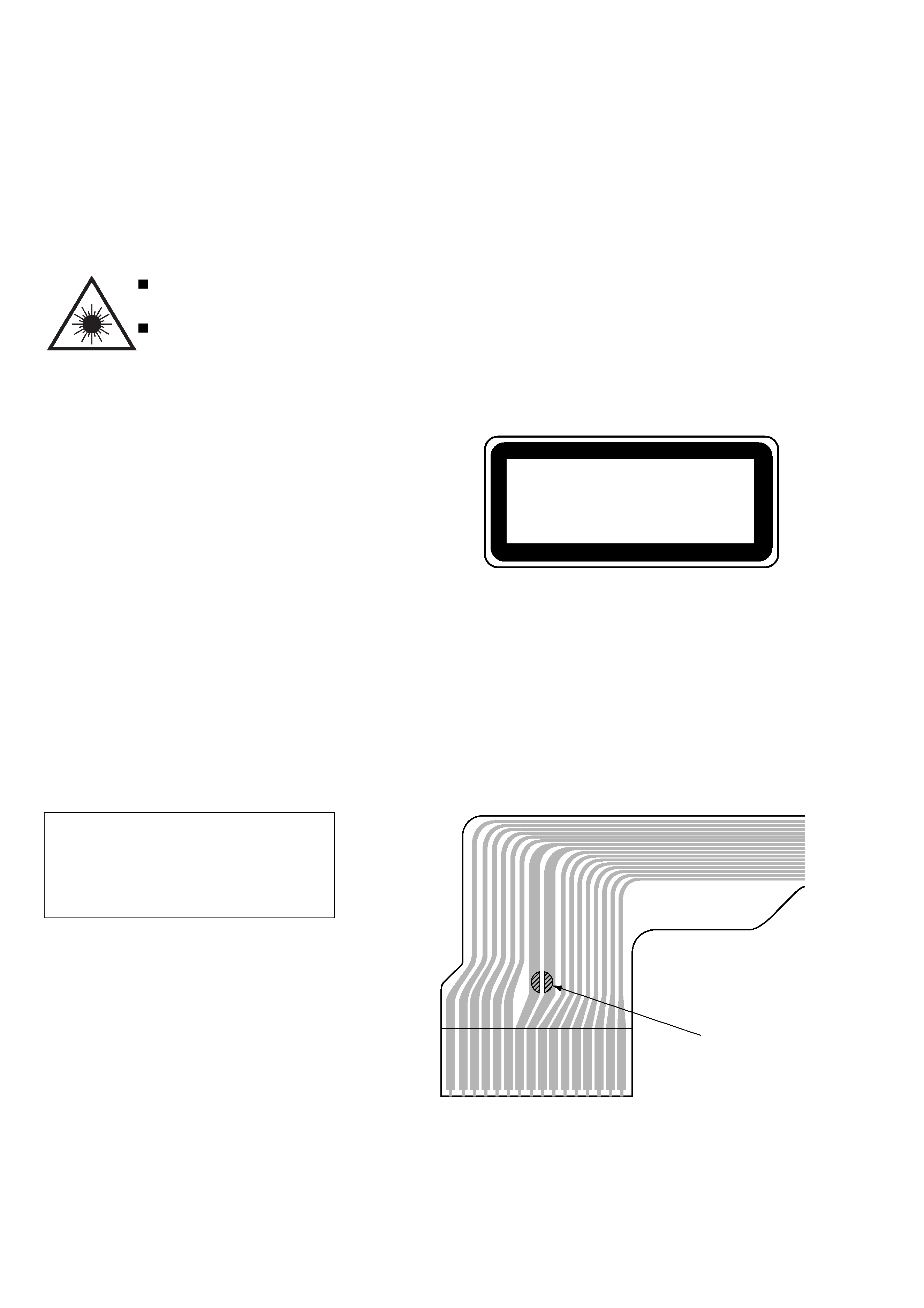
Body or clothes electrostatic potential could
ruin laser diode in the optical block. Be sure
ground body and workbench, and use care
the clothes do not touch the diode.
1) After the connection, remove solder
shown in the right figure.
Precaution to replace Optical block
PICKUP Assy PWB
16
10 9
1
Solder
5
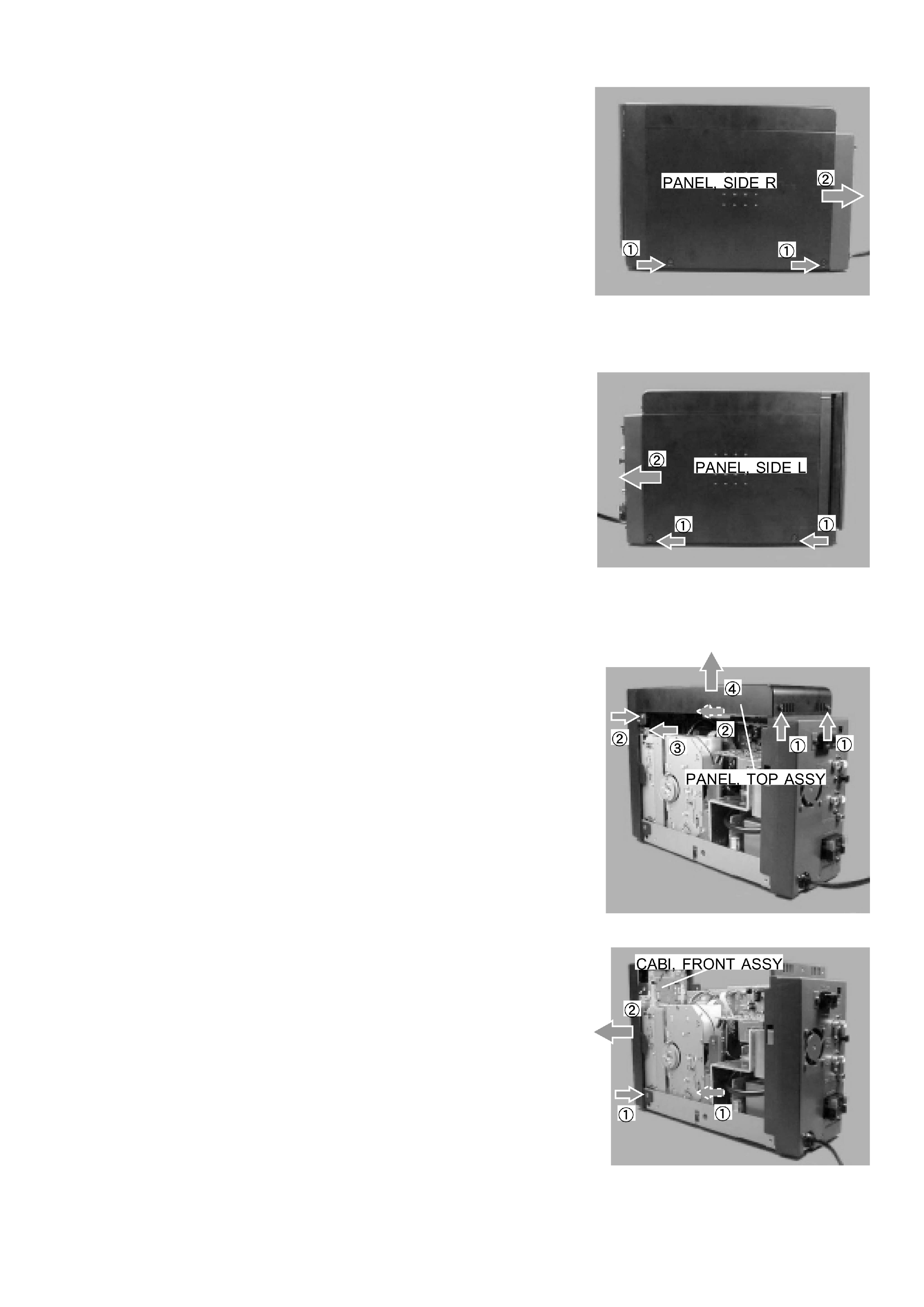
1. DISASSEMBLY OF AZG-X AND SERVICE POSITION
1) Disassembling the AZG-X
(1) Remove the two screws (1) and remove the PANEL, SIDE R (2).
DISASSEMBLY INSTRUCTIONS 1
(2) Remove the two screws (1) and remove the PANEL, SIDE L (2).
(3) Remove five screws (1), (2) and (3), and remove the PANEL, TOP
ASSY (4).
(4) Remove the two screws (1) and remove the CABI, FRONT ASSY.