SERVICE MANUAL
DA
TA
COLOR TELEVISION
TV-CN143 NH
S/M Code No. 09-003-415-9S1
SUPPLEMENT
· This Service Manual contains the additional information "NOTICES BEFORE
REPAIRING", "DISASSEMBLY INSTRUCTIONS" and "ADJUSTMENT" for the
model TV-CN143 (NH).
If requiring the other information, see Service Manual of TV-CN143 (NH),
(S/M Code No. 09-99B-415-9R1).
NOTICES BEFORE REPAIRING
To make the best use of this equipment, make sure to
obey the following items when repairing (or mending).
1. Do not damage or melt the tunicate of the leading
wire on the AC1 side, including the power supply
cord.
2. Do not soil or stain the letters on the spec.
inscription plates, notice labels, fuse labels, etc.
3. When repairing the part extracted from the
conducted side of the board pattern, fix it firmly
with applying bond to the pattern and the part.
4. Restore the following items after repairing.
1) Conditions of soldering of the wires (especially,
the distance on the AC1 side).
2) Conditions of wiring, bundling of wires, etc.
3) Types of the wries.
4) Attachment conditions of all types of the insulation.
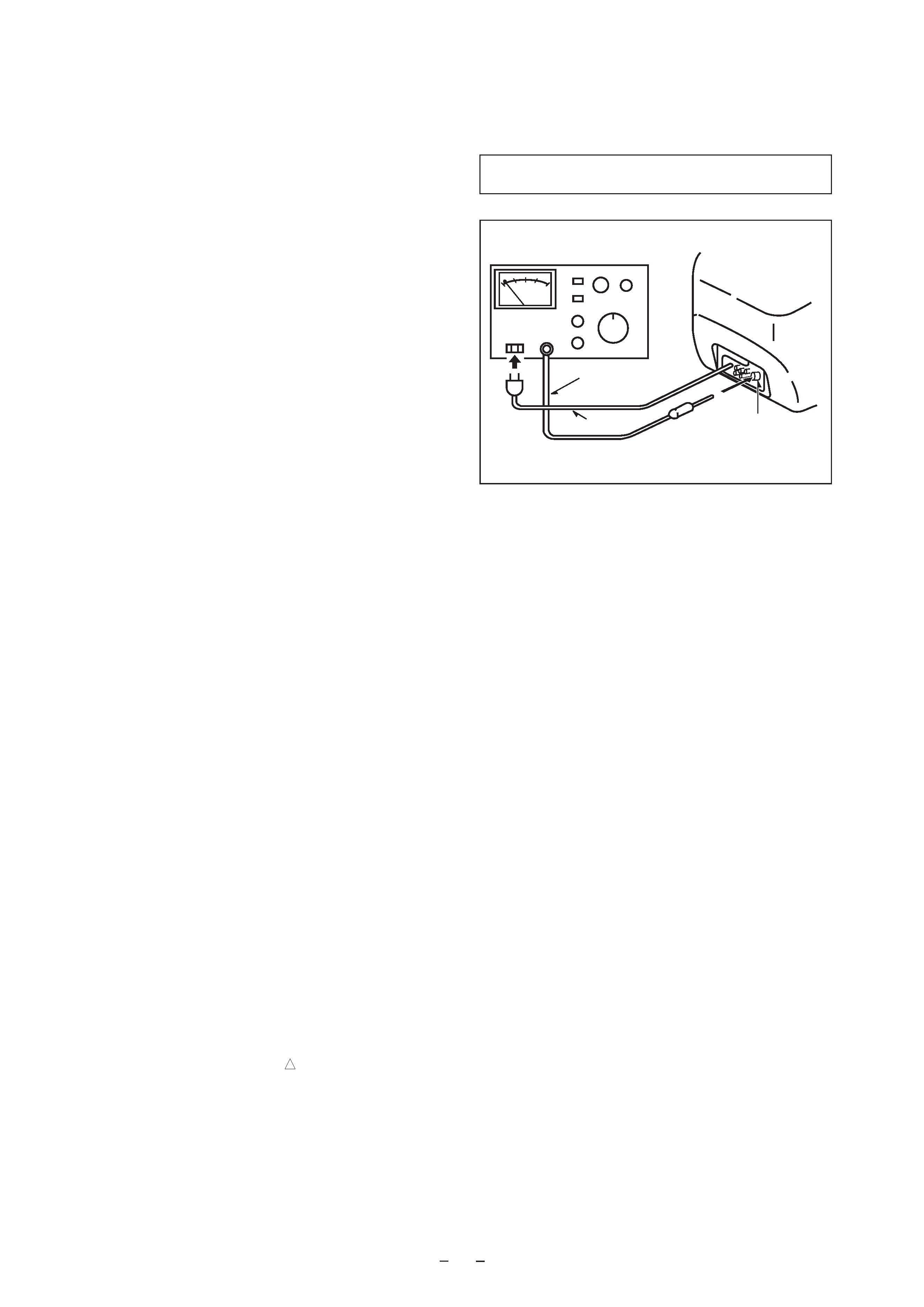
5. After repairing, always measure the insulation
resistance and perform the voltage-withstand test
(See Fig-1).
1) The insulation resistance must be 7.0 to 9.5 M
when applying
500V per second.
2) In the voltage withstand test, apply 3.6 kV for 3
seconds and check that the GO lamp lights.
*
Breaking current set to 10 mA.
*
Connect the safety checker as shown in Fig-1,
then measure the resistance and perform the test.
*
Do not touch the equipment during testing.
*
For details of the safety checker, refer to the supplied
Operation manual.
Fig-1
Safety checker (Model 7110, etc.)
Earth cable
AC cable
Connect the earth cable
to the outside metal part
terminal.
Insulation resistance: 7.0 to 9.5 M
(500 V/s)
Voltage-withstand: 3.6 kV for 3 or more seconds
When servicing and checking on the TV, note the followings.
board. The inside wiring is designed not to get close to
the pyrogenic parts and high voltage parts. Therefore,
put these parts in the original positions.
5. Take care of the cathode-ray tube.
By setting an explosion-proof cathode-ray tube in this
equipment, safety is secured against implosion.
However, when removing it or servicing from the
back, it gives out shock that is dangerous. Take
enough care to deal with it.
6. Avoid an X-ray.
Safety is secured against an X-ray by giving
considerations to the cathode-ray tube and the high
voltage peripheral circuit, etc. Therefore, when
repairing the high voltage peripheral circuit, use the
designated parts and do not change the circuit.
Repairing, except indicates, causes rising of high
voltage, and the cathode-ray tube emits an X-ray.
7. Perform a safety check after servicing.
Confirm that the screws, parts and wiring which were
removed in order to service are put in the original
positions, or whether there are deteriorated portions
around the places serviced.
1. Keep the notices.
As for the places which need special attentions, they
are indicated with labels or seals on the cabinet,
chassis and parts. Make sure to keep the indications
and notices in the operation manual.
2. Avoid an electric shock.
There is a high voltage part inside. Avoid an electric
shock while the electric current is flowing.
3. Use the designated parts.
The parts in this equipment have the specific
characteristics of incombustibility and withstand voltage
for safety.
Therefore, use a part which has the same character
as the replaced part. Especially as to the important
parts for safety which is indicated in the circuit
diagram or the table of parts with a
mark, the
designated parts must be used.
4. Put parts and wires in the original position after
assembling or wiring.
There are parts which use the insulation material such
as a tube or tape for safety, or which are assembled so
that these parts do not make contact with the printed
!
2
Anode cap
CRT GND
Hook
CRT
CRT GND
Grip
DISASSEMBLY INSTRUCTIONS
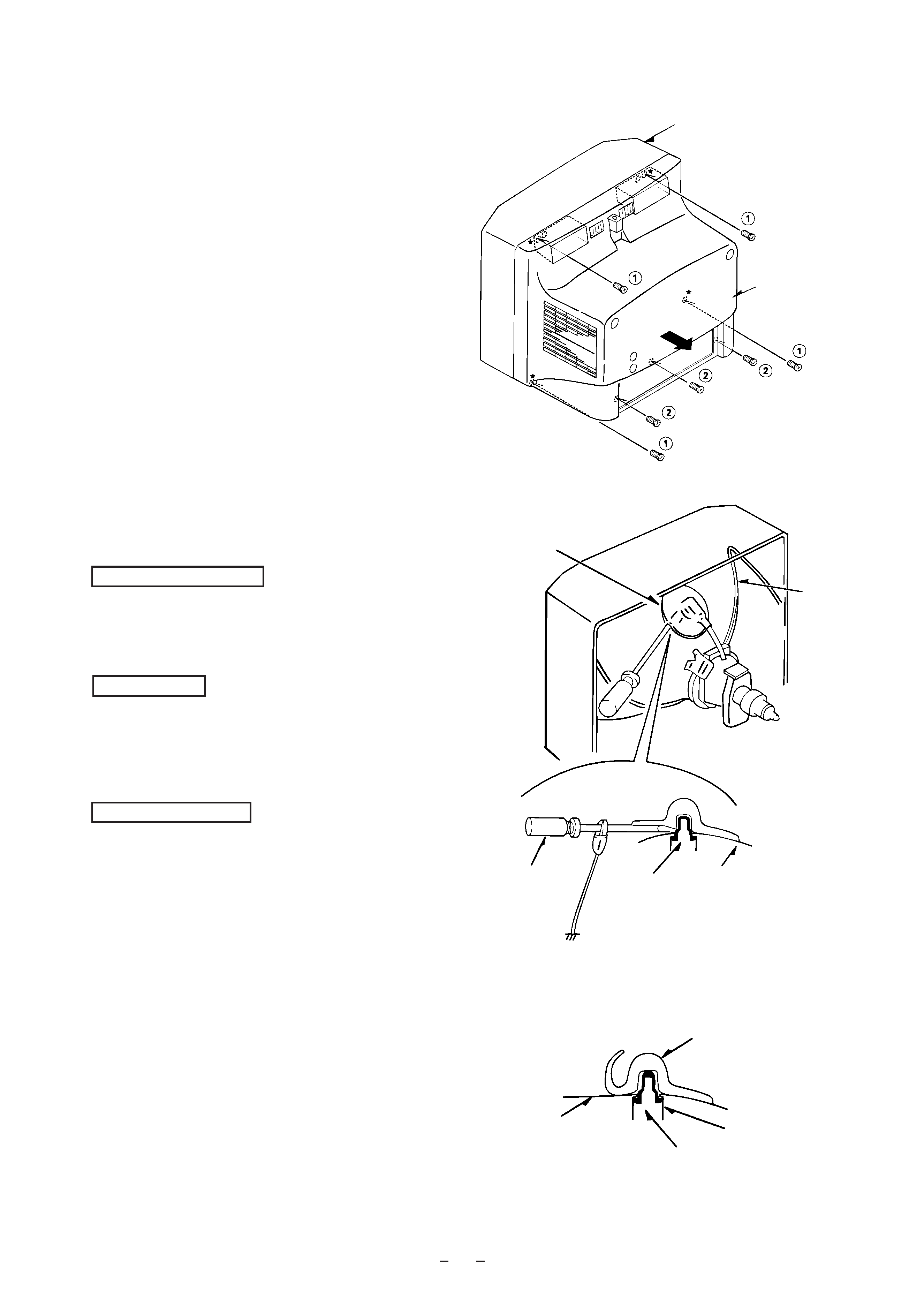
1. REAR CABINET REMOVAL
Figure 1-1
2. HIGH-VOLTAGE CAP (ANODE CAP) REMOVAL
2-1. Cautions before Removing
Discharge the anode voltage
(1)
The anode voltage is not discharged completely from the
CRT of this unit even after the power is turned off. Be
sure to discharge the residual anode voltage before
removing the anode cap.
Do not use pliers
(2)
Do not use pliers, etc. to remove the anode cap. If you
used pliers and bent the hook to remove the cap, the spring
characteristics of the hook could be lost, and when
reinstalled, the cap would come off from the CRT anode
button easily, causing an accident.
Do not turn the anode cap
(3)
If the anode cap is turned in the direction of its
circumference, the hook is likely to come off.
2-2. Anode Cap Removal
Discharge the anode voltage. (See Figure 2-1)
(1)
Connect a flat-bladed screwdriver to the CRT GND via
an alligator clip.
(2)
Use a tester to check the end of the screwdriver and ground
of the TV for continuity.
(3)
Touch the hook with the end of the screwdriver.
Caution : Be careful not to damage the anode cap.
(4)
Turn over the anode cap.
Caution : Be careful not to damage the anode cap.
Figure 2-1
Figure 2-2
Front cabinet
Rear cabinet
Anode cap
CRT
Hook
Anode button
(1)
Remove four screws 1 and three screws 2 , then remove
the rear cabinet in the direction of the arrow.
(See Figure1-1)
3
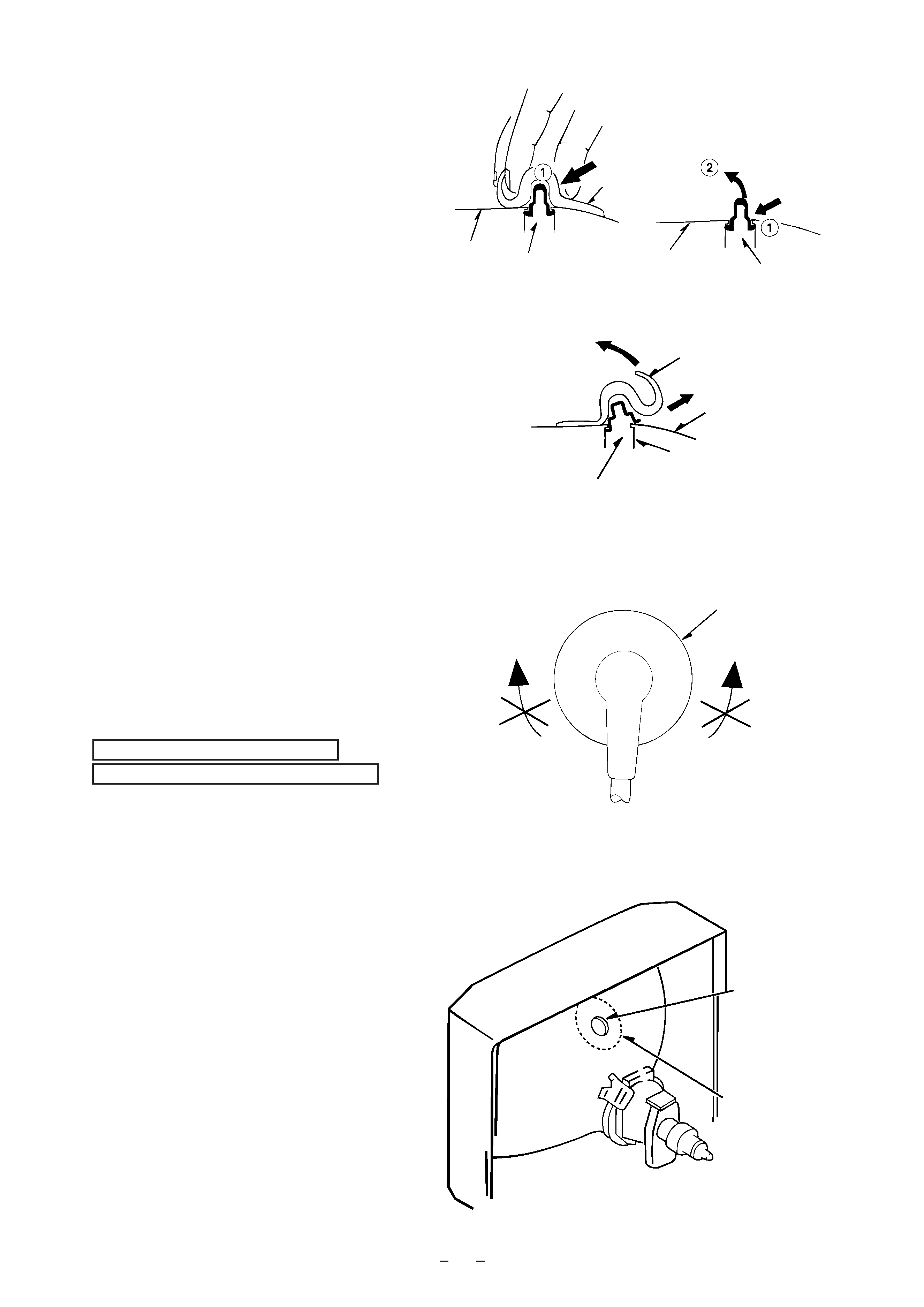
(5)
Push the anode cap with your thumb in the direction of
arrow 1
as shown in the figure, then lift the cap in the
direction of arrow 2
to release the hook on one side.
(See Figure 2-3)
(6)
Turn over the anode cap on the side where the hook was
released and pull out the cap in the direction opposite to
that on which the cap was pushed. (See Figure 2-4)
Caution : Do not pull out the anode cap straight up.
: Do not pull the cap forcibly. After removing
the cap, check that the hook is not deformed.
Figure 2-3
3. ANODE CAP REINSTALLTION
Observe the cautions carefully so that no accident occurs
due to a defect in installing the anode cap and so it does
not come off.
3-1. Caution before Reinstalling
Never turn the anode cap after installing it
Never re-use the hook when it has been deformed
(1)
If the anode cap is turned after it is installed, it may come
off. Therefore, arrange the high-voltage cable before
attaching the anode cap. (See Figure 3-1)
(2)
If you have attached the anode cap before arranging the
high-voltage cable, arrange the cable carefully so the cap
does not turn.
3-2. Anode cap reinstallation
(1)
Use a clean cloth moistened slightly with alcohol to clean
the installation section. (See Figure 3-2)
Caution : Check that the installation section is free from
dust, foreign matter, etc.
(2)
Coat the anode cap installation circumference with an
appropriate amount of the specified silicone grease (KS-
650N).
Caution : Be careful that silicone grease does not enter
the anode button.
CRT
CRT
Anode cap
Hook
Hook
Anode cap
Hook
Anode button
CRT
Left
Right
Anode cap
Anode button
Installation
section
Figure 2-4
Figure 3-1
Figure 3-2
4
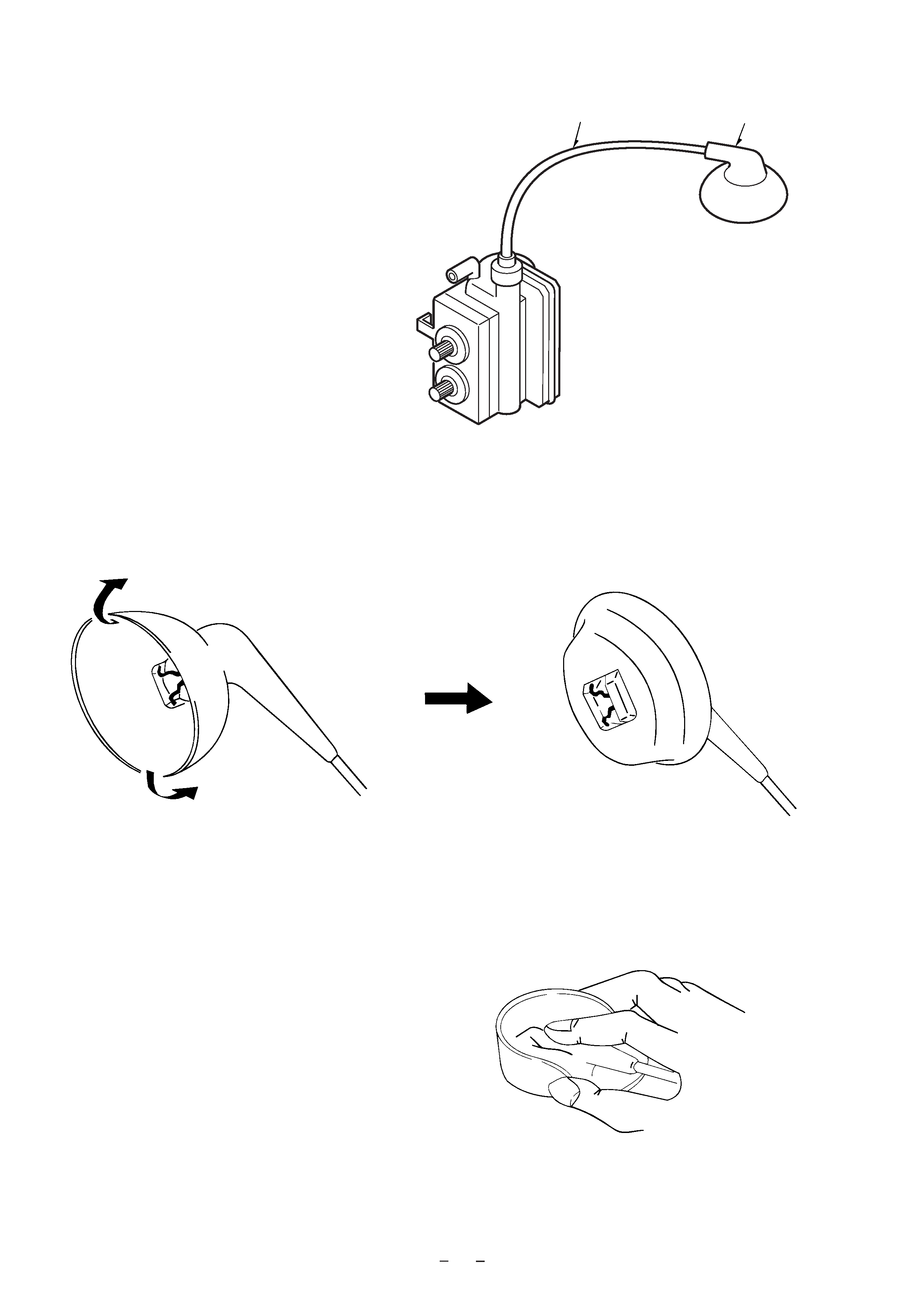
(3)
Eliminate twisting, etc. of the high-voltage cable and
arrange it so that no twisting occurs. (See Figure 3-3)
Caution : If the cable is not arranged correctly, the anode
cap could turn and cause an installation defect.
(4)
Turn over the rubber cap symmetrically on the left and
right. (See Figure 3-4)
Caution : Take great care not to damage the anode cap.
Figure 3-3
(5)
Fit your forefinger over the projection at the center of the
cap and hold the cap between your thumb and middle
finger. (See Figure 3-5)
High-voltage cable
Anode cap
Figure 3-4
Figure 3-5
5