SERVICE MANUAL
FM STEREO/FM-AM RECEIVER
US Model
Canadian Model
AEP Model
UK Model
STR-DB840/DB940
E Model
Australian Model
Chinese Model
STR-DB940
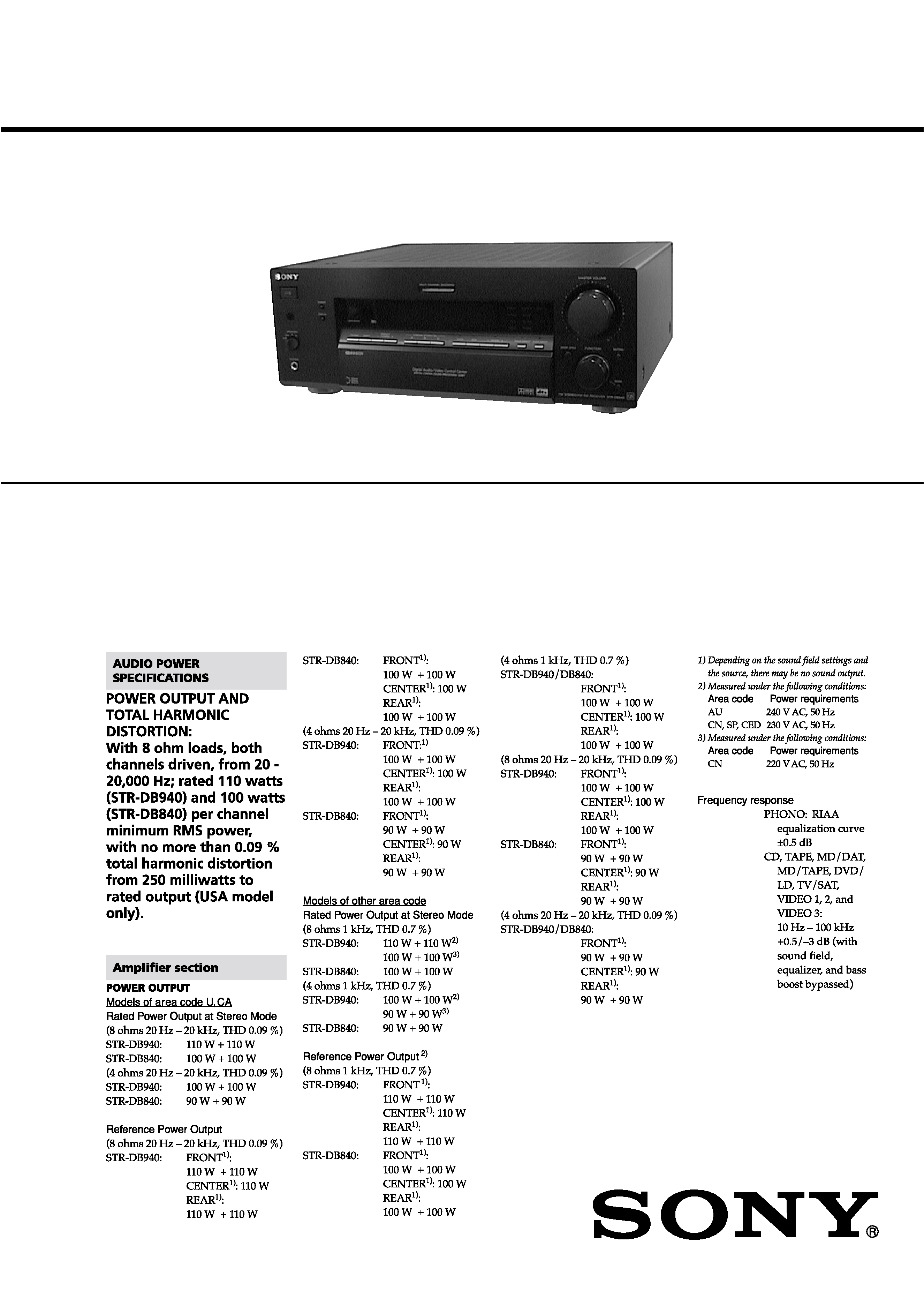
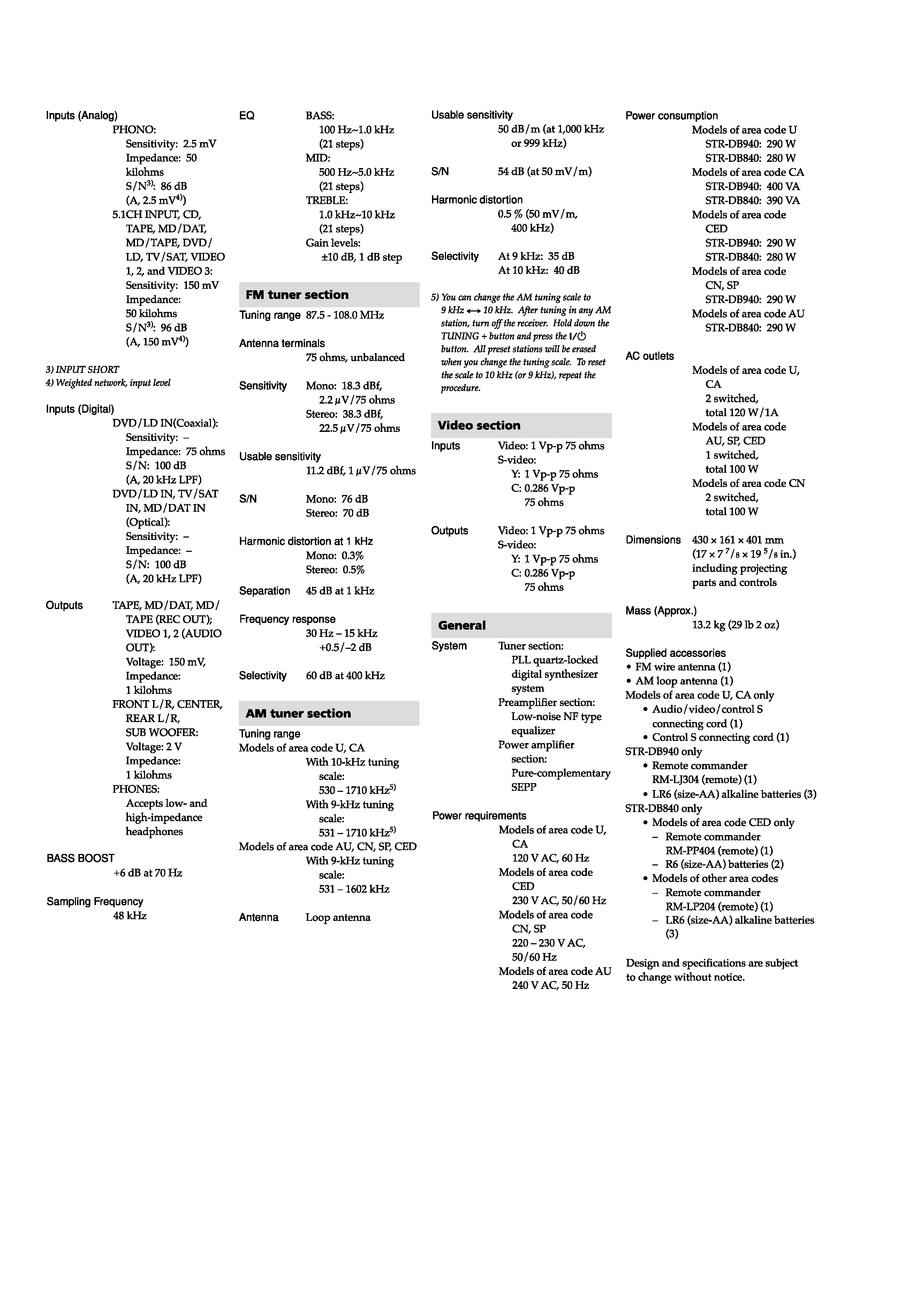
SPECIFICATIONS
STR-DB840/DB940
Photo: STR-DB940 (AEP and UK models) (Black type)
Continued on next page
Manufactured under license from Dolby laboratories. "Dolby", "AC-
3", "Pro Logic" and the double-D symbol ; are trademarks of Dolby
Laboratories.
Manufactured under license from Digital Theater Systems, Inc. US
Pat. No. 5,451,942 and other worldwide patents issued and pending.
"DTS" an d "DTS Digital Surround" are trademarks of Digital Theater
Systems, Inc.
2
· Abbreviation
AU : Australian model
CA : Canadian model
CED : AEP and UK models
CN : Chinese model
SP
: E model
U
: US model
3
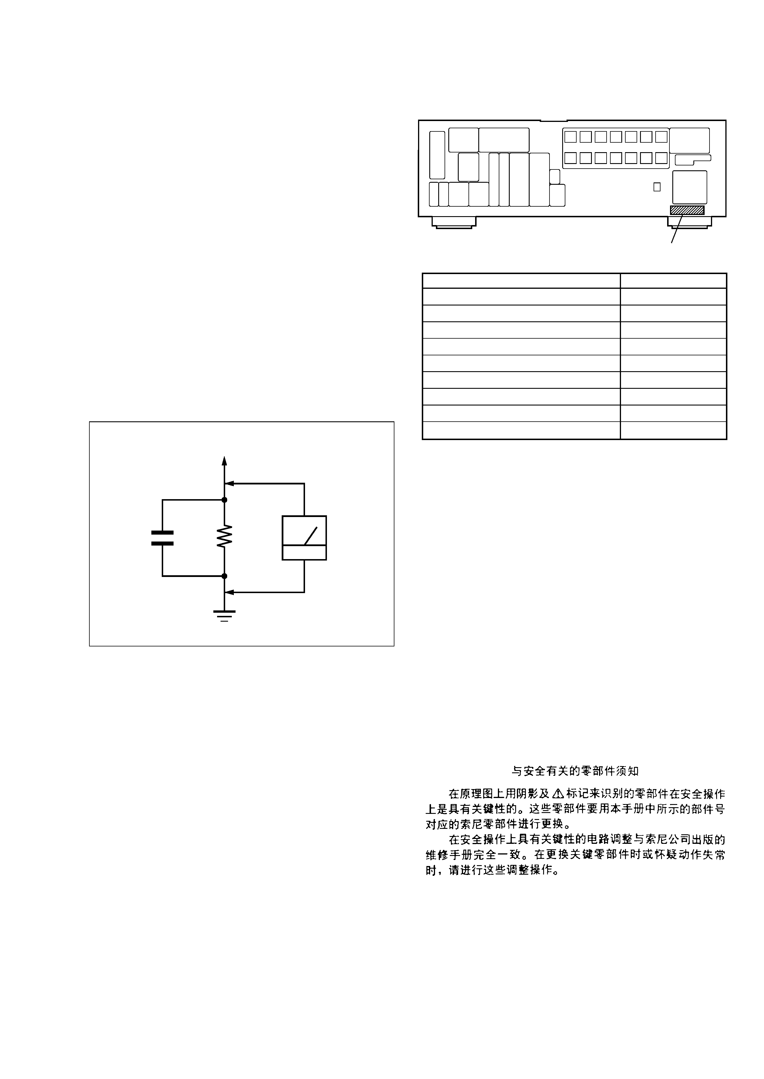
MODEL IDENTIFICATION
Rear View
Notes on chip component replacement
· Never reuse a disconnected chip component.
· Notice that the minus side of a tantalum capacitor may be dam-
aged by heat.
Flexible Circuit Board Repairing
· Keep the temperature of the soldering iron around 270 °C during
repairing.
· Do not touch the soldering iron on the same conductor of the
circuit board (within 3 times).
· Be careful not to apply force on the conductor when soldering or
unsoldering.
Fig. A.
Using an AC voltmeter to check AC leakage.
1.5 k
0.15
µF
AC
voltmeter
(0.75 V)
To Exposed Metal
Parts on Set
Earth Ground
SAFETY CHECK-OUT
After correcting the original service problem, perform the follow-
ing safety check before releasing the set to the customer:
Check the antenna terminals, metal trim, "metallized" knobs,
screws, and all other exposed metal parts for AC leakage.
Check leakage as described below.
LEAKAGE TEST
The AC leakage from any exposed metal part to earth ground and
from all exposed metal parts to any exposed metal part having a
return to chassis, must not exceed 0.5 mA (500 microamperes.).
Leakage current can be measured by any one of three methods.
1. A commercial leakage tester, such as the Simpson 229 or RCA
WT-540A. Follow the manufacturers' instructions to use these
instruments.
2. A battery-operated AC milliammeter. The Data Precision 245
digital multimeter is suitable for this job.
3. Measuring the voltage drop across a resistor by means of a VOM
or battery-operated AC voltmeter. The "limit" indication is 0.75
V, so analog meters must have an accurate low-voltage scale.
The Simpson 250 and Sanwa SH-63Trd are examples of a pas-
sive VOM that is suitable. Nearly all battery operated digital
multimeters that have a 2 V AC range are suitable. (See Fig. A)
Part No.
Model
DB940: US model
DB940: Canadian model
E model
Chinese model
Australian model
DB940: AEP and UK models
DB840: US model
DB840: AEP and UK models
DB840: Canadian model
Part No.
4-227-151-0s
4-227-151-1s
4-227-151-2s
4-227-151-3s
4-227-151-4s
4-227-151-5s
4-227-151-7s
4-227-151-8s
4-227-151-9s
ATTENTION AU COMPOSANT AYANT RAPPORT
À LA SÉCURITÉ!
LES COMPOSANTS IDENTIFIÉS PAR UNE MARQUE 0
SUR LES DIAGRAMMES SCHÉMATIQUES ET LA LISTE
DES PIÈCES SONT CRITIQUES POUR LA SÉCURITÉ
DE FONCTIONNEMENT. NE REMPLACER CES COM-
POSANTS QUE PAR DES PIÈCES SONY DONT LES
NUMÉROS SONT DONNÉS DANS CE MANUEL OU
DANS LES SUPPLÉMENTS PUBLIÉS PAR SONY.
SAFETY-RELATED COMPONENT WARNING!!
COMPONENTS IDENTIFIED BY MARK 0 OR DOTTED
LINE WITH MARK 0 ON THE SCHEMATIC DIAGRAMS
AND IN THE PARTS LIST ARE CRITICAL TO SAFE
OPERATION. REPLACE THESE COMPONENTS WITH
SONY PARTS WHOSE PART NUMBERS APPEAR AS
SHOWN IN THIS MANUAL OR IN SUPPLEMENTS PUB-
LISHED BY SONY.

4
TABLE OF CONTENTS
1.
GENERAL ................................................................... 5
2.
DISASSEMBLY ......................................................... 7
3.
TEST MODE .............................................................. 10
4.
DIAGRAMS
4-1. Block Diagram MAIN Section (1/2) ........................ 11
4-2. Block Diagram MAIN Section (2/2) ........................ 12
4-3. Block Diagram
DISPLAY/POWER SUPPLY Section ...................... 13
4-4. Note for Printed Wiring Boards and
Schematic Diagrams ...................................................... 14
4-5. Schematic Diagram DIGITAL Board (1/3) .............. 15
4-6. Schematic Diagram DIGITAL Board (2/3) .............. 16
4-7. Schematic Diagram DIGITAL Board (3/3) .............. 17
4-8. Printed Wiring Board
DIGITAL Board (Component Side) ......................... 18
4-9. Printed Wiring Board
DIGITAL Board (Conductor Side) ........................... 19
4-10. Printed Wiring Boards
VIDEO/JOINT (1) (Q) Boards (DB840) .................. 20
4-11. Schematic Diagram
VIDEO/JOINT (1) (Q) Boards (DB840) .................. 21
4-12. Printed Wiring Boards
OSD/JOINT (2) (Q) Boards (DB940) ...................... 22
4-13. Schematic Diagram
OSD/JOINT (2) (Q) Boards (DB940) ...................... 23
4-14. Printed Wiring Board AU SW Board ....................... 24
4-15. Schematic Diagram AU SW Board .......................... 25
4-16. Printed Wiring Board S-VIDEO Board .................... 26
4-17. Schematic Diagram S-VIDEO Board ....................... 27
4-18. Printed Wiring Board DISPLAY Board .................... 28
4-19. Schematic Diagram DISPLAY Board ...................... 29
4-20. Printed Wiring Board MAIN Board ......................... 30
4-21. Schematic Diagram MAIN Board (1/3) ................... 31
4-22. Schematic Diagram MAIN Board (2/3) ................... 32
4-23. Schematic Diagram MAIN Board (3/3) ................... 33
4-24. Printed Wiring Boards H.P/MUTING/POWER/SW/
VOL/VIDEO 3 Boards ................................................. 34
4-25. Schematic Diagram H.P/MUTING/POWER/SW/
VOL/VIDEO 3 Boards ................................................. 35
4-26. Printed Wiring Boards 5.1 IN/BIAS (C)/BIAS (L)/
BIAS (LS)/BIAS (R)/BIAS (RS) Boards .................... 36
4-27. Schematic Diagram 5.1 IN/BIAS (C)/BIAS (L)/
BIAS (LS)/BIAS (R)/BIAS (RS) Boards .................... 37
4-28. Printed Wiring Boards DC (1)/DC (2) Boards .......... 38
4-29. Schematic Diagram DC (1)/DC (2) Boards .............. 39
4-30. Printed Wiring Boards AC/SP Boards ....................... 40
4-31. Schematic Diagram AC/SP Boards .......................... 41
4-32. IC Pin Function Description ........................................... 48
5.
EXPLODED VIEWS ................................................ 59
6.
ELECTRICAL PARTS LIST ............................... 63
5
SECTION 1
GENERAL
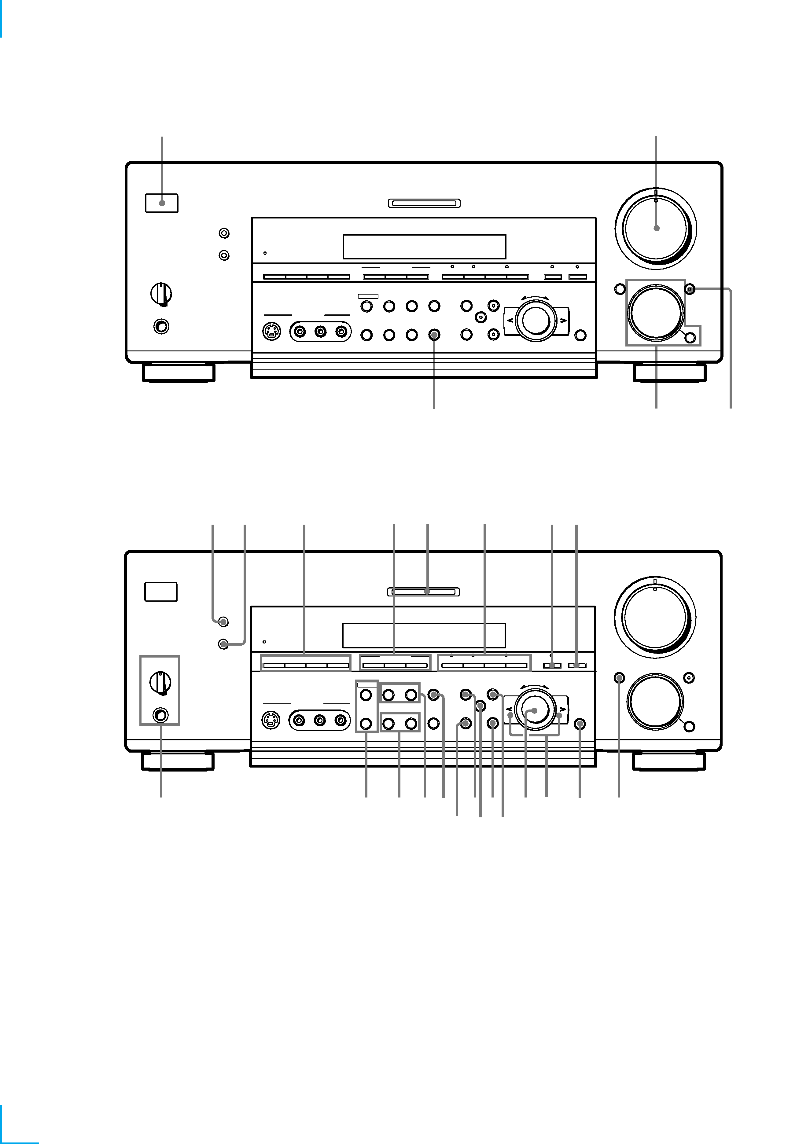
FRONT PANEL PARTS DESCRIPTION
1
2
3
4
5
5
0
1
3
9
7
46
2
8
10
·
·
·
·
·
·
·
·
·
·
·
·
·
·
·
·
·
·
·
·
·
·
·
·
·
·
·
·
·
·
PHONES
SPEAKERS
A
OFF
A
+B
B
MASTER VOLUME
DIMMER
DISPLAY
VIDEO 3 INPUT
R
L
VIDEO
S-VIDEO
AUDIO
FM MODE
BASS BOOST
MEMORY
MULTI CHANNEL DECODING
+
·
·
·
·
ENTER
DOOR OPEN
FUNCTION
MUTING
+
C
2 CH
ANLG DIRECT
5.1CH INPUT
FM / AM
PRESET
TUNING
CINEMA STUDIO EX.
MODE
+
SHIFT
AB
A.F.D.
INPUT
MODE
SET UP
NAME
LEVEL
EQ
+
EQUALIZER
SUR
MODE
?/1
6
qf
qg
7
8
9
q;
qa
qs qd
qh
qj
qk
ql
w;
wa
ws
wd
wf
wg
wh
wj
1 I/1 switch
2 MASTER VOLUME control
3 MUTING button
6 DIMMER button
7 DISPLAY button
8 FM/AM button
SHIFT button
PRESET TUNING +/ buttons
9 CINEMA STUDIO EX. A~C buttons
q; MULTI CHANNEL DECODING
indicator
qa A.F.D. button/indicator
2CH button/indicator
MODE +/ buttons/indicator
qs ANLG DIRECT button
qd 5.1CH INPUT button
qf DOOR OPEN button
qg ENTER button
qh Cursor buttons (</>)
qj Jog dial
qk LEVEL button
ql EQ button
w; SUR button
wa SET UP button
ws NAME button
wd EQUALIZER button
wf TUNING/PTY SELECT +/ buttons
(AEP and UK models)
TUNING +/ buttons
(Except AEP and UK models)
4 FUNCTION control
MODE button
5 INPUT MODE button
wg RDS EON button
(AEP and UK models)
RDS PTY button
(AEP and UK models)
TEST TONE button
(Except AEP and UK models)
SLEEP button
(Except AEP and UK models)
wh MEMORY button
FM MODE button
wj SPEAKERS selector
PHONES jack