1
TOSHIBA V 226B
U-View Limited
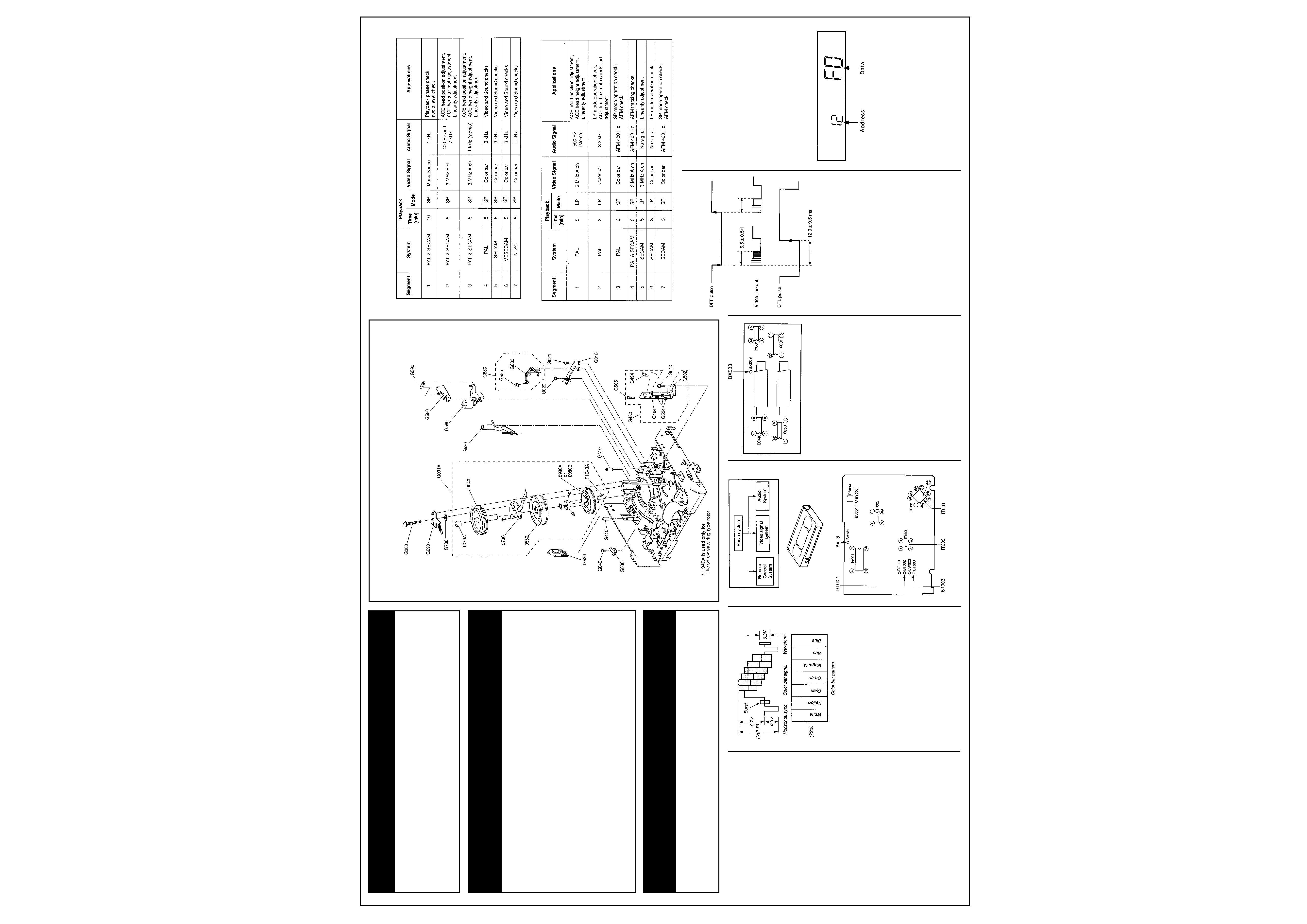
Alignment tape specifications
[1] ST-C6
[2] ST-C7
Matrix
Item
See Model
Book
Deck Alignment ........................................................................ Toshiba V 856 B
6
Mech. Adjustments .................................................................. Toshiba V 856 B
6
Deck Exploded View .................................................................Toshiba V 856 B
6
Power Supply ............................................................................ Toshiba V 426 B
6
IF Tuner ...................................................................................... Toshiba V 426 B
6
Servo Logic ............................................................................... Toshiba V 426 B
6
Audio Diagram .......................................................................... Toshiba V 426 B
6
0001C
70061687
Owners Manual
English
0014C
70012604
Power Cord
0250
70051847
Front Panel
RS041
70041671
Res, Fusible
18
J 0.3W
RT135
70041236
Res, Fusible
1
J 0.4W
RW012
70041074
Res Fusible
27
J 0.3W
RW021
70040126
Res Fusible
CP001
70040056
Cap, Plastic
100nF
M 275V
CP002
70041047
Cap, Electrolytic
47
µF
M 385V
CP003
70041646
Cap, Ceramic
2.2nF
M 400V
RP018
70041078
Res, Fusible
1.5
J 0.3W
RP021
70041673
Res, Fusible
2.2k
J 0.3W
RP041
70041081
Res, Fusible
0.1
F 0.4W
RP042
70040456
Res, Fusible
10
J
RP051
70041116
Res, Fusible
39
J 0.3W
RP071
70040125
Res, Carbon
47
J 0.3W
RP091
70041081
Res, Fusible
0.1
F 0.4W
RP092
70041670
Res Fusible
120
J 0.3W
BP001
70011176
Inlet
FP001
70010445
Fuse, 1A, 250V
LP001
70011950
Line Filter
LP002
70011949
Line Filter
LP020
70011948
Power Transformer
Recommended Safety Parts
Item
Part No.
Description
Electrical Adjustments
<Test equipment required>
Adjustment will be performed with the following
test equipment.
1. Color TV (Monitor)
2. Oscilloscope, 2 CHs, 15 MHz or higher with
delay system
3. Frequency counter (7 digits or higher)
4. Millivoltmeter
5. Digital voltmenter
6. Tester(20k
/V)
7. Audio generator
8. Audio attenuator
9. Alignment tapes
Part code: ST-C6: 70909409, ST-C7:
70909410
10. Alignment screw driver (jig)
11. Color pattern generator
12. Video sweep generator
<Color bar signal>
Color bar signals of 75% recorded on the
alignment tapes are shown in Fig. 2-1-1.
Fig. 2-1-1
<Specified input and output levels, and
impedance>
Video input: Negative sync, standard composite
video signal 1 V(p-p), 75
Video output: Same as the video input 1 V(p-p),
75
Audio input: 308 mV(rms), more than 47 k
(phono type), more than 10 k
(21 pin type)
Audio output: 308 mV(rms), less than 4.7 k
(phono type), less than 1.0 k
(21 pin type)
<Alignment sequence>
Recorded the alignments in the sequence as
shown in Fig. 2-1-2.
Mechanical Parts List
Item
Part No.
Description
0040
70904091
Upper Cylinder Assy
0550
70031711
Lower Cylinder Assy
0730
70090527
PC Board Assy
Pre Amp
0980B
70031620
Rotor (Press Fit Securing Type)
1070A
70031559
Ground Cap
G001A
70031686
Cylinder Assy
Exploded Parts View
Upper Cylinder Assembly
Fig. 2-1-2
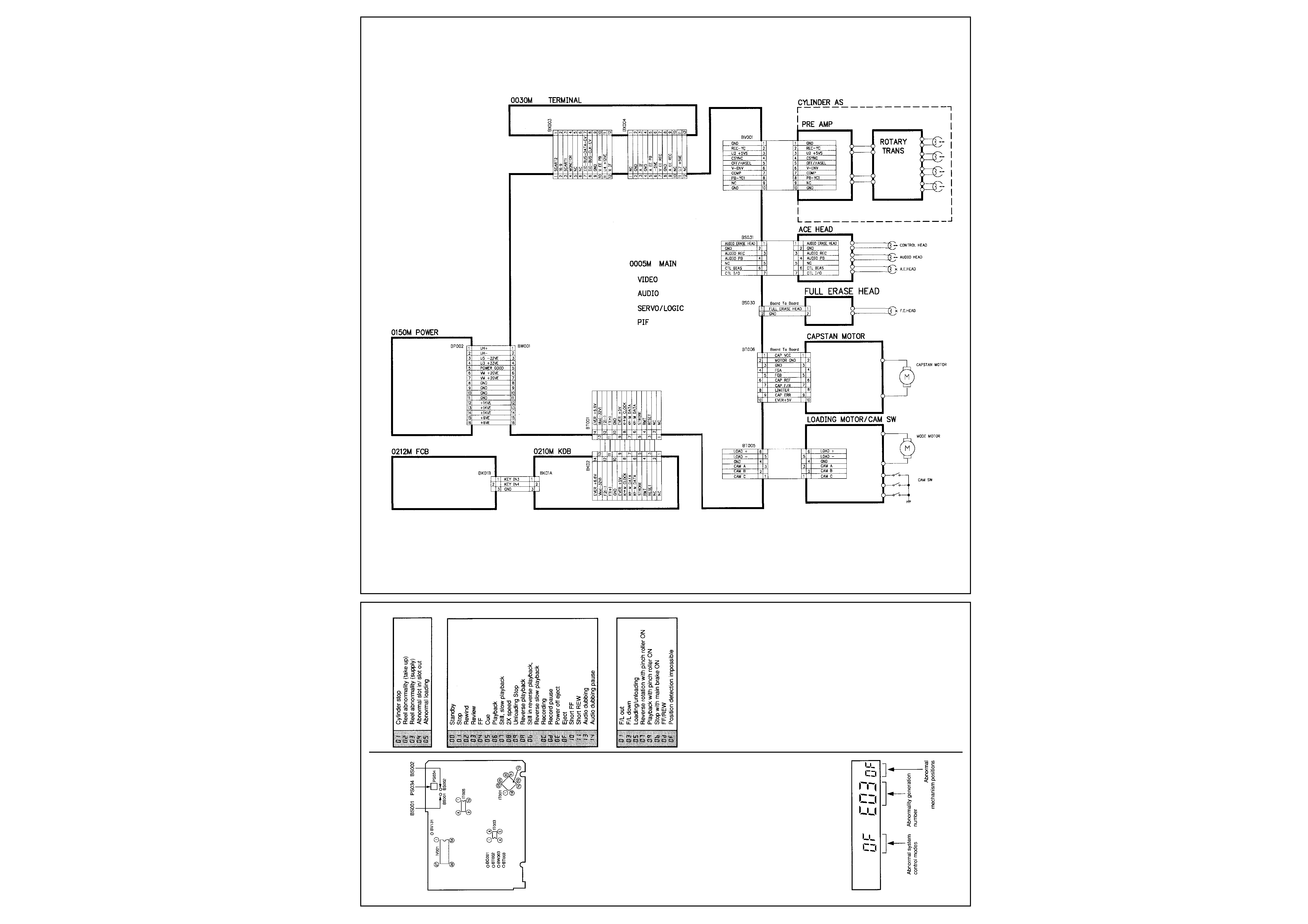
2-1. Servo Circuit
Main PC Board
Terminal PC Board
2-1-1. Playback Phase (PG) Adjustment
Test point: BT002, BT003, BX008 (Video out)
Test equipment: Oscilloscope
1. Confirm that phase difference between the fall
of the DFF pulse (BT002) and the rise of CTL
pulse (BT003) is 12.0
± 0.5 ins.
2. Further, observe the envelope (BVI 31)
waveform, and confirm that the ACE head
position adjustment and linearity adjustment
have been made, and C-SYNC (pin 70 of
IT001) is being input during playback.
3. Set the VTR to the STOP mode.
4. Press the unit's channel up/down buttons
simultaneouly for more than 5s.
5. Afterwards, within 2s, press the PLAY button
on the remote controller.
6. The automatic adjustment will be made for
about 10s, all the displays will blink. If the
automatic adjustment is not carried out,
confirm that the alignment tape has a safety
tab or not, and redo from the step 3.
1) When adjustment has been completed:
The display will blink for 10s, stop blinking
and return to the normal display in the STILL
mode, then it shifts to the playback display in
the playback mode.
2) When adjustment fails:
It goes into the STOP mode.
7. Confirm that the play indicator is displayed,
and confirm that the rising and falling edge of
the SW pulse is 6.5
± 0.5H from the V-sync
front edge of the video signal.
2-1-2. In Case of IT003 is Replaced
When IT003 is replaced, the data in the VTR is
required to memorize in the new one. So
perform the following procedures.
1. Press the channel up/down buttons on the
VTR simultaneously for more than 5s while
the display blinks and the unit is in the power
off mode.
2. And then within 2s, press the CANCEL button
on the remote controller.
3. After displaying the address at the channel
display area and the data at the minute
display area, set the address to 12 using the
channel up/down buttons on the remote
controller.
Next, set the data to F0 using the EF/REW
buttons on the remote controller. The data
goes up using FF button and down using
REW button.
4 Perform the adjustement described in the item
"2-1-1. Playback Phase (PG) Adjustment".
5. Pull out the power cord plug from the AC
outlet once and insert the power cord plug into
the AC outlet again.
6. Perform the channel presetting as the 1T003
replaced has no channel data.
Continues Next Page...
2
TOSHIBA V 226B
www.u-view.co.uk
Electrical Adjustments
Cont'd
2-2. Audio Circuit
Main PC Board
2-2-1. Bias Level Adjustment
Test Point: BS001, BS002
Test equipment: Millivoltmeter
Adjusting point: PS034
1. Set the VTR to record mode.
2. Connect BS001 to the millivoitmeter and
B5002 to GND.
3. Adjust PS034 to obtain 3.6
± 0.1 mV(rms).
2-3. Self Diagnosis Function
2-3-1. Outline
When a tape running stops or the VTR enters
the power OFF mode, etc. due to some
abnormality, the abnormality is stored in the
EEPROM and displayed on the display tube.
2-3-2. Storing abnormal modes
· The abnormality is classed into 5 groups, and
the abnormality number, system control
mode, and the mechanism position at which
the abnormality occurred are stored in the
EEPROM.
· The writing timing is just after the abnormality
occurred.
2-3-3. Abnormality mode display
· Press the CH UP and CH DOWN buttons on
the VTR simultaneously for more than 5s.
· And then within 2s, press the STILL button on
the remote control.
· The system control mode at which the
abnormality occurred is displayed at the
channel display area, "E" is displayed at the
hour digit, abnormality generation number is
displayed at the minute digit, and the
mechanism position is displayed in the
second digit position.
· The abnormality mode is displayed regardless
of the power on off.
· When the Counter Reset button is pressed in
the display period, the abnormality display data
is initialized and "-" is displayed.
The data displayed are as follows:
Abnormality generation number
Abnormal system control modes
Abnormal mechanism positions
Positions 0, 2, 4 exist as mechanism positions.
For example, 8 shows a position between 7 and
9 (between playback position and review
position).
Wiring Diagram
3
TOSHIBA V 226B
U-View Limited
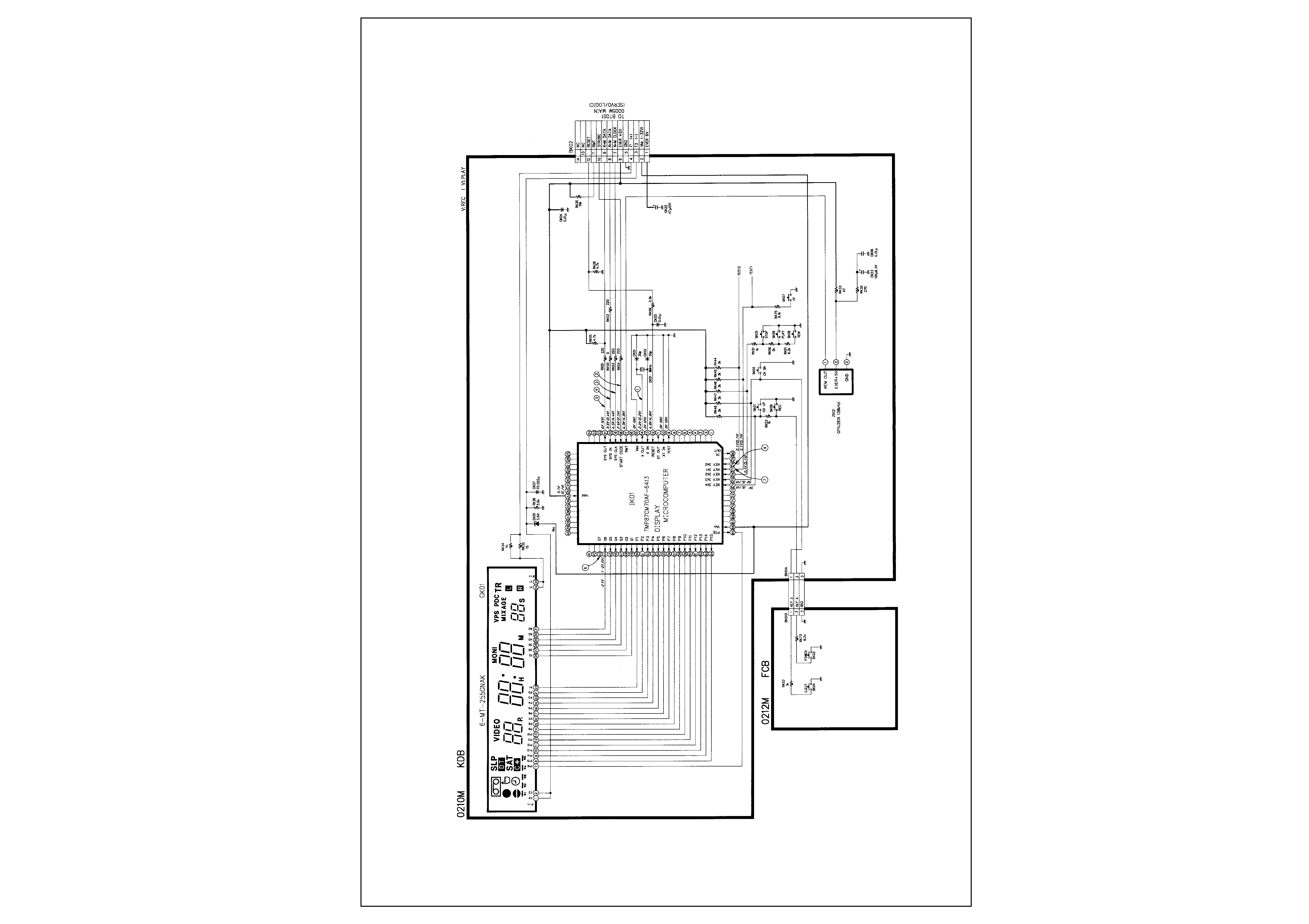
Keyboard Front Display Diagram
4
TOSHIBA V 226B
www.u-view.co.uk
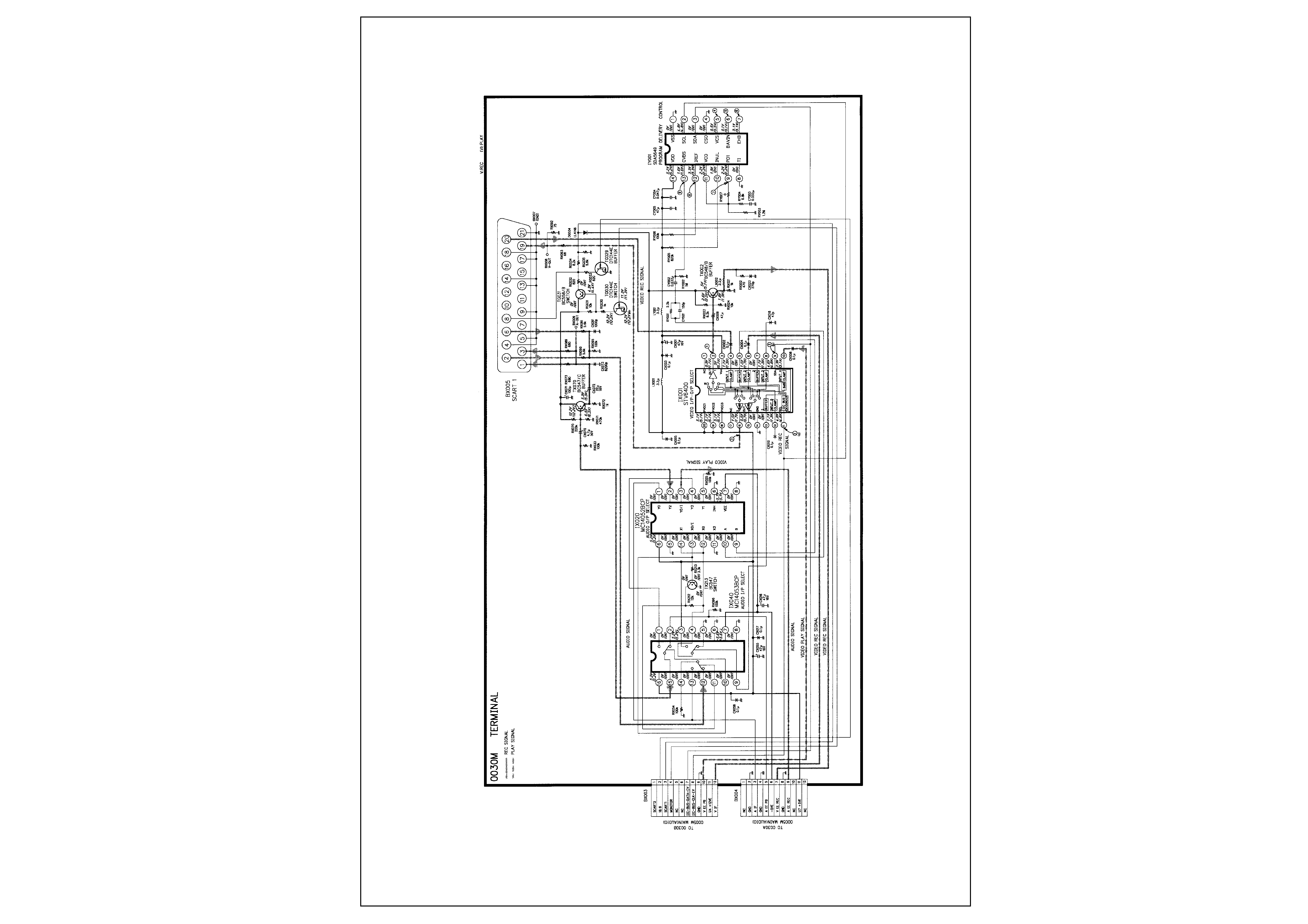
Scart AV Switching Diagram
5
TOSHIBA V 226B
U-View Limited
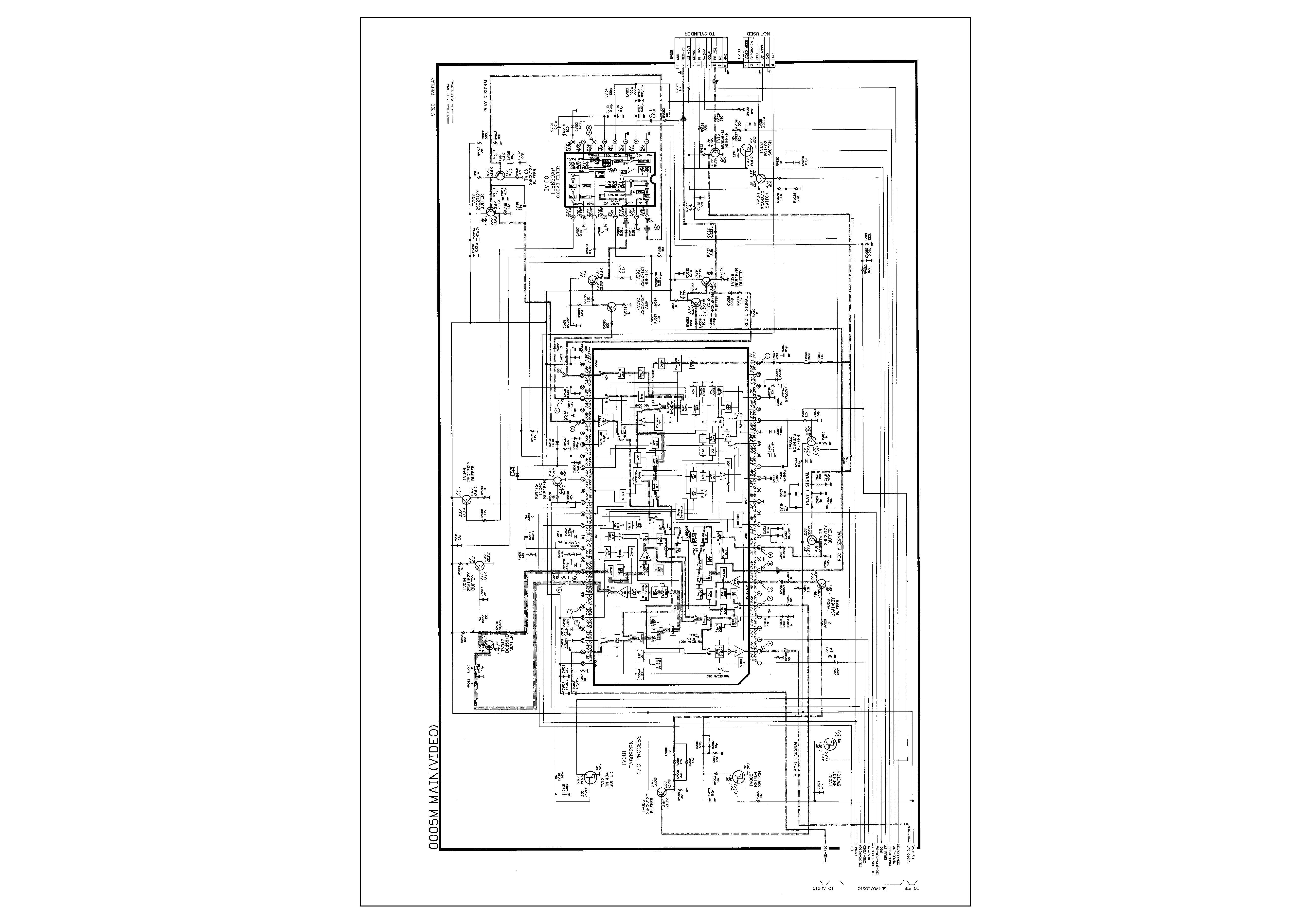
Video Diagram