
SERVICE MANUAL
PUBLISHED IN JAPAN, Dec., 1998
FILE NO. 2B0-9813
SX-2258
CORDLESS TELEPHONE

-- 1 --
CONTENTS
SAFETY PRECAUTIONS ...................................................................................................................... 1
OPERATING CONTROLS ..................................................................................................................... 2
BLOCK DIAGRAMS ............................................................................................................................... 3
SCHEMATIC DIAGRAMS ...................................................................................................................... 5
TROUBLESHOOTING HINTS ............................................................................................................. 14
IC AND TRANSISTOR VOLTAGE CHART ......................................................................................... 20
SEMICONDUCTOR LEAD IDENTIFICATION ..................................................................................... 31
ELECTRICAL PARTS LOCATION ...................................................................................................... 39
WIRING DIAGRAMS ........................................................................................................................... 44
EXPLODED VIEW AND MECHANICAL PARTS LIST ........................................................................ 46
PARTS LIST ........................................................................................................................................ 47
ASSEMBLY PARTS LIST .................................................................................................................... 74
SPECIFICATIONS ............................................................................................................................... 75
SUPPLEMENT FOR CHANGE NOTICE ............................................................................................. 78
SAFETY PRECAUTIONS
Before returning any models to the customer, a safety check of the entire instrument should be made.
The service technician must be sure that no protective device built into the instrument by the manufacturer
has become defective or inadvertently degraded during servicing.
1. WARNING:
Alterations of the design or circuitry of these models should not be made.
Any design changes or additions such as, but not limited to, circuit modifications, auxiliary speaker
jacks, switches, grounding, active or passive circuitry, etc. may alter the safety characteristics of these
models and potentially create a hazardous situation for the user.
Any design alterations or additions will void the manufacturer's warranty and will further relieve the
manufacturer of responsibility for personal injury or property damage resulting therefrom.
2. PRODUCT SAFETY NOTICE
Many electrical and mechanical parts in this chassis have special characteristics. These characteristics
often pass unnoticed and the protection afforded by them cannot necessarily be obtained by using
replacement components rated for higher voltage, wattage, etc. Replacement parts that have these
special safety characteristics are identified in this manual and its supplements; electrical components
having such features are identified by a
in the schematic diagram and the parts list. Before replacing
any of these components, read the parts list in this manual carefully. The use of substitute replacement
parts that do not have the same safety characteristics as specified in the parts list may create shock, fire
or other hazards.
-- 2 --
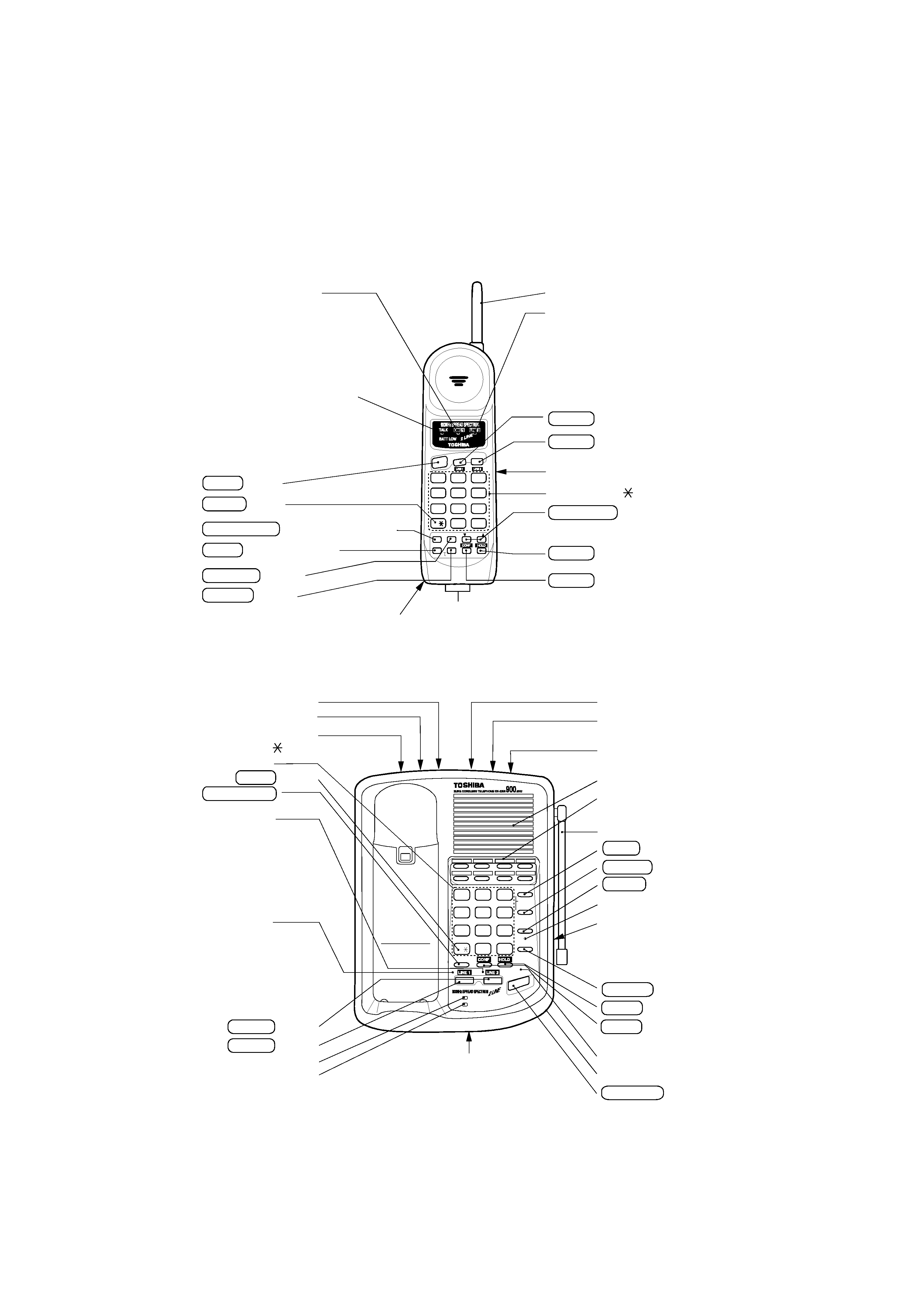
OPERATING CONTROLS
BASE UNIT CONTROLS
HANDSET CONTROLS
12
3
45
6
78
9
0#
ABC
DEF
JKL
MNO
GHI
TUV
WX
PQ
RS
YZ
TONE
OPER
FLASH/RDL INTCOM
VOL/RING
TALK
Charging Contacts
TALK button
TALK/BATT LOW LED (Red)
· Lights when the handset is used for
a phone conversation on line 2.
· Blinks when the base unit or
additional phone is in use on line 2.
· Blinks when line 2 is put on hold.
· Blinks when line 2 is ringing.
TONE button
FLASH/RDL (Flash/Redial) button
MEM
(Memory) button
PAUSE
button
LINE 2 LED (Orange)
INTCOM
button
Dialpad (1~9,
and # Dial Buttons)
HOLD
button
LINE 1 button
LINE 2 button
VOL/RING
(Volume/Ringer volume) button
CONF
(Conference) button
SPEED DIAL INDEX (back)
Battery compartment (back)
LINE 1 LED (Green)
· Lights when the handset is used for
a phone conversation on line 1.
· Blinks when the base unit or
additional phone is in use on line 1.
· Blinks when line 1 is put on hold.
· Blinks when line 1 is ringing.
· Standby status : OFF
· Lights ON during a phone
conversation using the handset.
· Blinks when a channel is changed,
and during the low battery status
and mute status.
MEM
PAUSE
PRIVACY
12
Antenna
12
3
45
6
78
9
0
#
ABC
DEF
JKL
MNO
GHI
TUV
WX
PQ
RS
YZ
TONE
OPER
FLASH/RDL
CHARGE
POWER
SPEAKER
INTCOM
MUTE
PAUSE
PRIVACY
MEM
1
2
TONE button
· Lights when the base unit is used
as speaker phone on line 1.
· Blinks when the handset or
additional phone is in use on
line 1.
· Blinks when line 1 is put on hold.
· Blinks when line 1 is ringing.
· Lights when the base unit is used
for a phone conversation on line 2.
· Blinks when the handset or
additional phone is in use on
line 2.
· Blinks when line 2 is put on hold.
· Blinks when line 2 is ringing.
TEL LINE 1/2 jack
TEL LINE 2 jack
DC IN 9V jack
Tone/Pulse switch
Line 1 ringer
volume switch
Antenna
SPEAKER volume control
Speaker
One-touch dialing keys
(1 to 8)
MEM (Memory) button
PAUSE button
MUTE button
INTCOM LED (Green)
SPEAKER button
SPEAKER LED (Green)
SPEED DIAL INDEX
Microphone
LINE 2 LED (Orange)
LINE 1 LED (Green)
LINE 2 button
CHARGE LED
POWER LED
TONE button
LINE 1 button
FLASH/RDL
(Flash/Redial) button
INTCOM button
Line 2 ringer
volume switch
CONF (Conference)
button
HOLD button
· Pull out the SPEED DIAL INDEX
card to find out a destination name
associated with a number preset
in the speed dial memory.
Dialpad (1~9,
and #
Dial Buttons)
-- 3 --
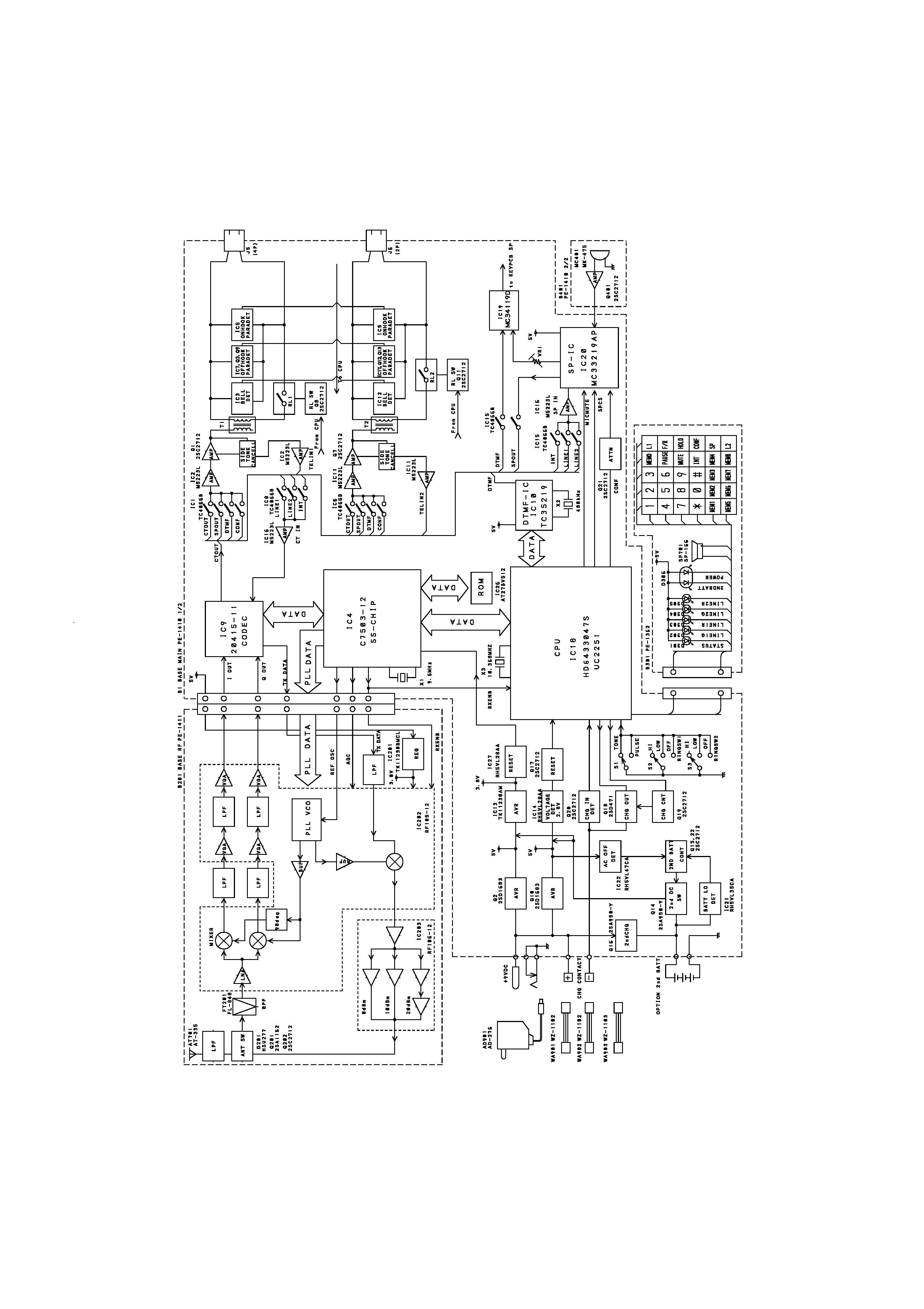
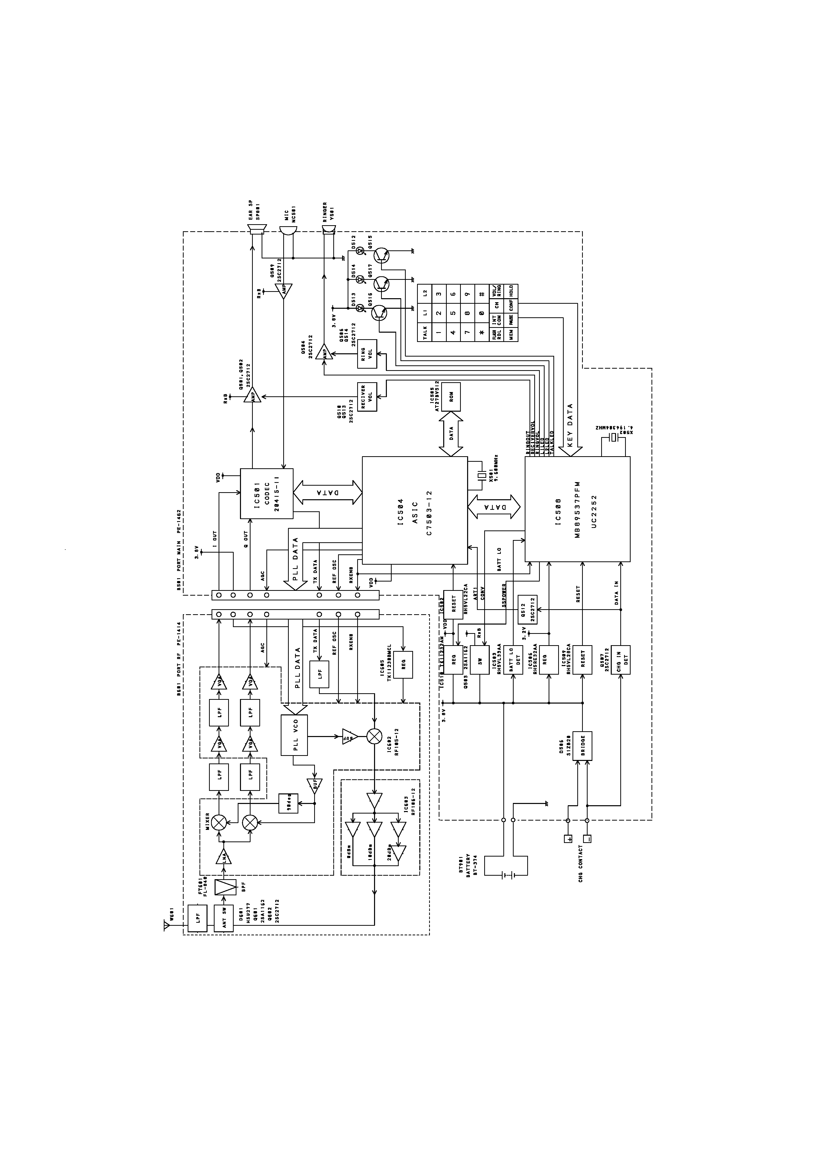
BLOCK DIAGRAMS
Base
-- 4 --
Handset