
SERVICE MANUAL
CORDLESS TELEPHONE
PRINTED IN CHINA, MAR,1999
FILE NO. 2B0-9809
SX-2007A

CONTENTS
SAFETY PRECAUTIONS .................................................................................... 1
OPERATING CONTROLS ................................................................................... 2
ALIGNMENT PROCEDURE ............................................................................... 5
BLOCK DIAGRAM .............................................................................................. 6
SCHEMATIC DIAGRAMS .................................................................................. 7
TROUBLE SHOOTING......................................................................................... 9
IC AND TRANSISTOR VOLTAGE CHART .................................................14
SEMICONDUCTOR LEAD IDENTIFICATION ..............................................24
ELECTRICAL PARTS LOCATION .................................................................31
WIRING DIAGRAMS ..........................................................................................33
EXPLODED VIEW AND MECHANICAL PARTS LIST .............................35
PART LIST ...........................................................................................................39
SPECIFICATIONS ................................................................................................55
SAFETY PRECAUTIONS
Before returning any TOSHIBA DSSS to the customer , a safety check of the entire instrument
should be made. The service technician must be sure that no protective device build into the
instrument by the manufacturer has
become defective or inadvertently degraded during
servicing.
1.WARNING:
Alterations of design or circuitry of these models should not be made.
Any design changes or additions such as, but not limited to, circuit modifications, auxiliary
speaker jacks, switches, grounding, active or passive circuitry, etc. may alter the safety
characteristics of these models and potentially create a hazardous situation for the user.
Any design alterations or additions will void the manufacturer's warranty and will further relieve
the manufacturer of responsibility for personal injury or property damage resulting therefrom.
2.PRODUCT SAFETY NOTICE
Many electrical and mechanical parts in this chassis have special characteristics. These
characeristics often pass unnoticed and the protection afforded by them cannot necessarily be
obtained by using replace ment component rated for higher voltage, wattage, etc. Replacement
parts that have these special safety characteristics are identified in this manual and its
supplements electrical components having such features are identified by a
in the
schematic diagram and the parts list . Before replacing any of these components read the parts
list in this manual carefully. The use of sunstitute replacement parts that do not have the same
safety characteristics as spectified in the parts list may create shock , fire or other hazards.
!
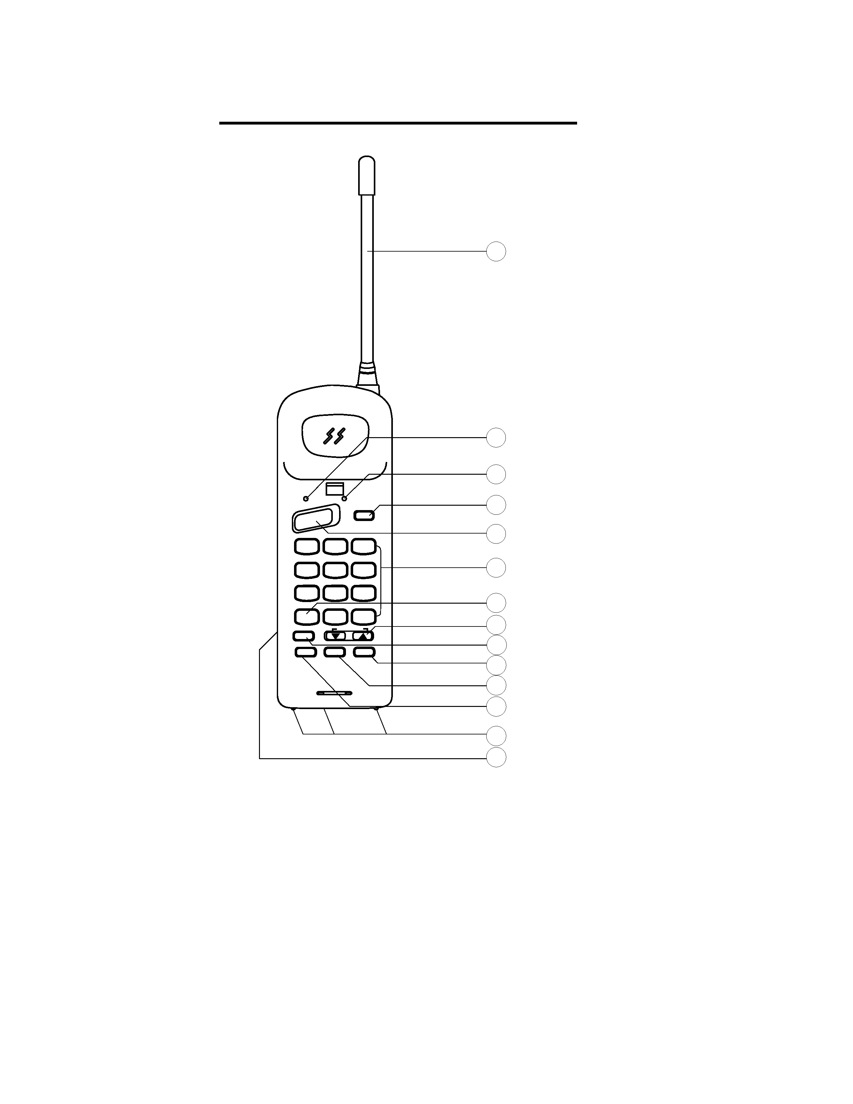
OPERATING CONTROLS
1. Flexible Antenna - purable high - gain flexible antenna.
2. TALK LED - The LED lights when the handset is in talk mode.
3. Batt / Range - Blinks on and off at different Frequency when the handset battery needs to be recharged /
Handset too far from base.
4.FLASH/RINGER TONE- Access services such as call waiting and call Forwarding / Four different types ringing
tones selected.
5. Talk button - Places Handset into talk mode / places Handset into standby mode when the Handset is in talk
mode.
6. Dialing key - Used for dialing numbers, storing numbers in menory.
7.TONE- Temporary set the telephone into tone mode.
8.VOL/RING VOLUME- Control the loudness of the receiver and the ringer.
9. Mute - Temporarily turn off the microphone / To go back the Two way conversation press Mute key again.
10.REDIAL/PULSE- Redials the last number dialed / To insert a pause in a phone number.
11.HOLD- To put a call on hold.
12.MEMORY- Used when storing number in memory / To diail a number from memory.
13.CHARGE CONTACTS- Provides power to charger the handset when it is placed on the base unit.
14. BATTERY PACK (BACK).
1
2
3
4
6
7
8
ANTENNA
TALK BUTTON
TALK LED
5
12
11
BATT/RANGE LED
FLASH/RINGER TONE KEY
DIALING KEYS(0-9)
TONE
VOL/RING VOLUME KEY
MUTE
REDIAL/PULSE
HOLD
9
10
MEMORY
CHARGING CONTACTS
TALK
BATT/RANGE
FLASH
1
ABC
2
DEF
3
GHI
4
JKL
5
MNO
6
PQ
RS 7
WX
YZ 9
TUV
8
OPER
0
#
*
MUTE
HOLD
RDL/P
MEM
VOL/RING
TOSHIBA
900MHz DIGITAL
SPREAD SPECTRUM
RINGER TONE
TONE
13
14 BATTERY PACK (BACK)
Handset Unit
Base Unit
TOSHIBA
SS
Transmission
Spread
Spectrum
900MHz
Digital
900MHz DIGITAL
SPREAD SPECTRUM
SX-2007
SPARE BATT
IN USE
CHARGER
POWER
PAGE
1
7
ANTENNA
SPARE BATTERY LED
IN USE LED
CHARGER LED
POWER LED
SPARE BATTERY CHARGER
PAGE KEY
CHARGING CONTACTS
2
3
4
5
6
8
TOLL FREE CUSTOMER SERVICE
1-800-631-3811
SPEED DIAL INDEX
01
02
03
04
05
06
07
08
09
10
11
12
13
14
15
16
17
18
19
20
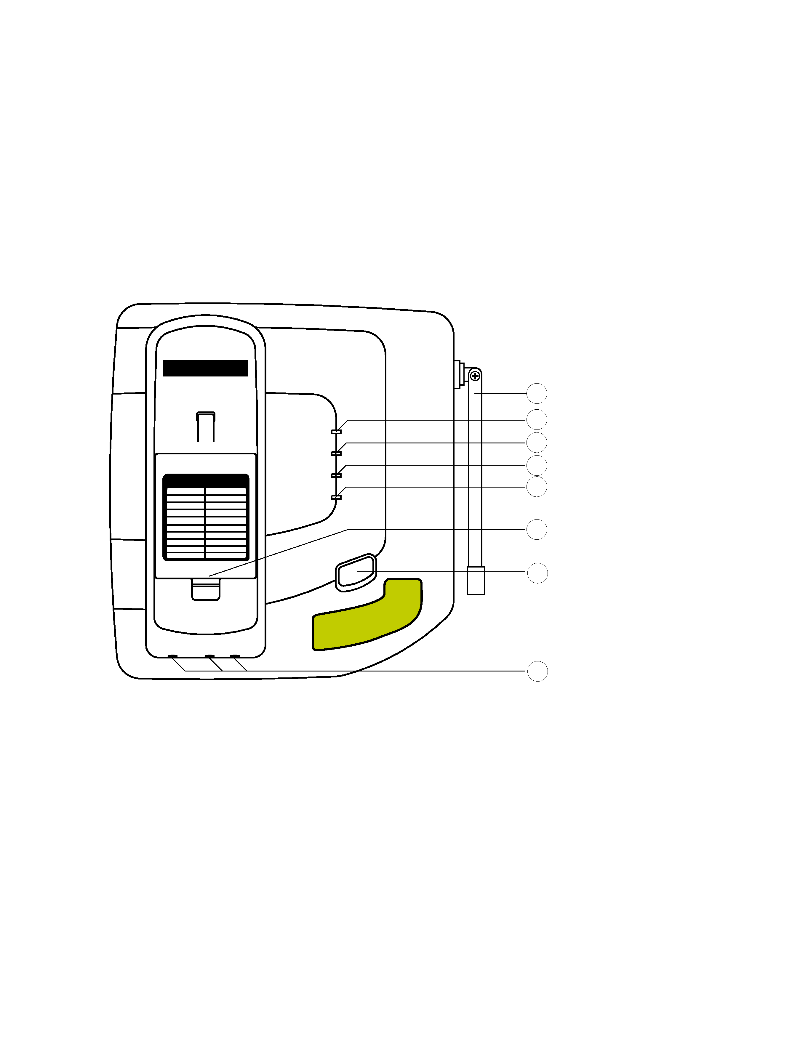
1. Antenna - Durable high - fain rod antenna.
2. SPARE BATT LED - Illuminates steadily when a battery is placed in the base unit charge cradle.
3. IN-USE LED - Illuminates when handset is off hook (line engaged).
4. CHARGE LED - Goes on when the handset is in teh cradle and the battery is charging.
5. POWER LED - Illuminates when power is applied to base unit.
6. Memory Dialing cord - Memeory location recording .
7. PAGE - To page the handset , press page key once.Pressing the PAGE a second time will cancel
the page.
8. Charging Contacts - Provides power to charge the handset when it is placed on the base unit.
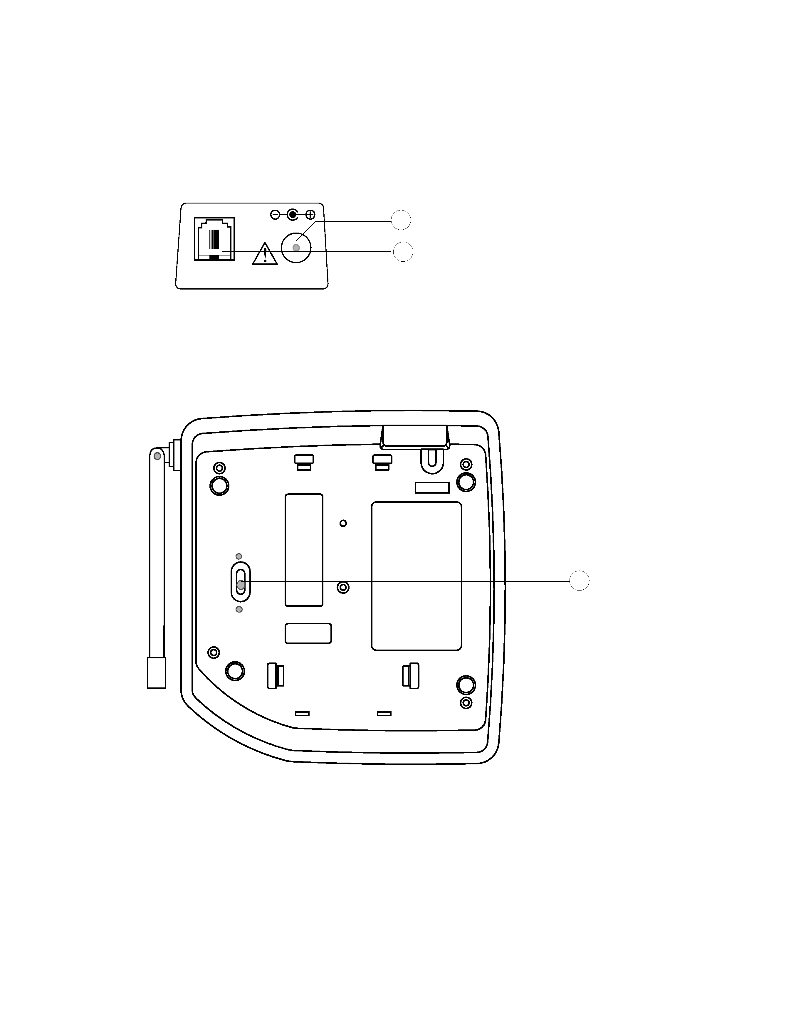
TEL.LINE
DC 9V
PHONE CORD JACK
REAR SIDE OF UNIT
POWER ADAPTOR JACK
PULSE
T
ONE
TONE / PULSE
SWITCH
9. Phone Cord Jack - Plugs one end of the telephone line cord into standard RJ11
telephone line jack and the other end into.
10. POWER ADAPROR JACK - Insert one of the plugs into the jack.
11. TONE/ PULSE Switch - Set the dialing mode between DTMF and PULSE.
9
10
11